Note: Descriptions are shown in the official language in which they were submitted.
CA 03030207 2019-01-08
WO 2018/007452 PCT/EP2017/066790
Title: Heat exchanger for quenching reaction gas
The invention relates to a heat exchanger for quenching reaction
gas.
Such a device is generally known, and may for example be found on
a cracking furnace of an ethylene production plant, where it is used to
quickly cool down cracked gas, in order to avoid secondary reactions. A heat
exchanger for quenching reaction gas generally comprises
- a coolable double-wall tube including an inner tubular wall and an outer
tubular wall, wherein said inner tubular wall is configured to convey said
reaction gas to be quenched, and wherein a space defined by said inner
tubular wall and said outer tubular wall is configured to convey a coolant;
- a tubular connection member having a bifurcating longitudinal cross-
section comprising an exterior wall section and an interior wall section
defining an intermediate space filled with refractory filler material, wherein
a converging end of said connection member is arranged to be in connection
with an uncoolable reaction gas conveying pipe, wherein said exterior wall
section is connected with said outer tubular wall of said coolable double-wall
tube, wherein an axial gap is left between said interior wall section and said
inner tubular wall of said coolable double-wall tube;
- a sealing member configured to seal said axial gap between said interior
wall section and said inner tubular wall of said coolable double-wall tube.
Examples of such heat exchangers can be found for instance in
document US 5,732,981 disclosing a joint between a hot unrefrigerated pipe
and a refrigerated pipe, with the end of the unrefrigerated pipe bifurcating
in cross-section, and including a flexible component, an 0-ring for instance,
between, and resting tight against, the face of the refrigerated pipe and that
of the interior section of the unrefrigerated pipe. However, a disadvantage of
this prior art device is that the sealing member may get damaged, as the
sealing member may get crushed when an interior wall section of said
CA 03030207 2019-01-08
WO 2018/007452 PCT/EP2017/066790
2
tubular connection member axially expands due to the passage of hot
reaction gas. Without proper sealing, hot reaction gas may leak into the
intermediate space filled with refractory filler material, which may get
damaged in this way as well.
US 2010/0319888 discloses another example of a prior art heat
exchanger for cooling reaction gas. In an attempt to better protect the
sealing member, the sealing member cannot be reached anymore from an
inner side of the tubular connection member, which seriously complicates
exchange of said sealing member in case such an exchange turns out to be
necessary, for example in case of wear after a certain time.
Another problem with these prior art heat exchangers is that said
refractory filler material may get damaged or crushed due to the difference
in thermal expansion between the interior wall section and the exterior wall
section of said tubular connection member.
A further problem lies in the lack of efficient flow of coolant in the
space defined by said inner tubular wall and said outer tubular wall of said
coolable double-wall tube.
It is an aim of the present invention to solve or alleviate one or
more of the above-mentioned problems. Particularly, a first aspect of the
invention aims at providing an improved heat exchanger for quenching
reaction gas, which provides an effective sealing of the refractory filler
material during the different temperature ranges of all stages of the
process. It is another aim of the invention to provide a heat exchanger,
which can be repaired efficiently in case of need. A second aspect of the
invention aims at providing an improved heat exchanger for quenching
reaction gas, which provides a compensation for the difference in thermal
expansion between the interior wall section and the exterior wall section of
said tubular connection member. A third aspect of the invention aims at
providing an improved heat exchanger for quenching reaction gas, which
CA 03030207 2019-01-08
WO 2018/007452 PCT/EP2017/066790
3
can provide an efficient flow of coolant in said space defined by said inner
tubular wall and said outer tubular wall of said coolable double-wall tube.
To these aims, according to a first aspect of the present invention,
there is provided a heat exchanger for quenching reaction gas characterized
by the features of claim 1. In particular, an edge of said inner tubular wall
engaging said sealing member comprises an at least partly bevelled edge
including a bevel engaging said sealing member. As the sealing member
engages a bevel of an at least partly bevelled edge of said inner tubular
wall,
the sealing member can be gradually shifted along said bevel during axial
thermal expansion of said interior wall section of said tubular connection
member, thus partially compensating the thermal expansion difference
between said interior wall section and said exterior wall section of said
tubular connection member. In this way, crushing of said sealing member
between an edge of said inner tubular wall and an axially expanding
interior wall section of said tubular connection member can be avoided.
In a preferred embodiment, said sealing member may comprise
slidingly overlapping thinned ends. When joining said slidingly overlapping
thinned ends, a ring-like sealing member can be formed. Due to the axially
limited space between said inner tubular wall and said interior wall section
of said tubular connection member, where the sealing member is located,
thermal expansion of said sealing member will in particular result in
circumferential expansion of said sealing member, which can be
compensated by said slidingly overlapping thinned ends so that good sealing
can be obtained at different temperature ranges, in a more efficient way
than with a closed loop sealing member. At the same time, said slidingly
overlapping thinned ends can also compensate for a slight change in
diameter of said ring-like sealing member due to a gradual shift of said
sealing member along said bevel during axial thermal expansion of said
interior wall section of said tubular connection member.
CA 03030207 2019-01-08
WO 2018/007452
PCT/EP2017/066790
4
Advantageously, said sealing member can comprise a spring-like
element arranged to press said sealing member against said at least partly
bevelled edge of said inner tubular wall. Elasticity of said spring-like
element can ensure a good sealing at all temperature ranges. In particular,
said spring-like element can ensure that the sealing member quickly
returns to its original shape during shutdown, which is accompanied by a
sudden drop in temperature.
In a more preferred embodiment, said edge of said inner tubular
wall may be bevelled radially inwardly. Such a radially inward beveling has
the advantage that the sealing member can be located at a location which
can be reached from an inner side of said tubular connection member, thus
facilitating maintenance in case it is needed. Alternatively, said edge of
said
inner tubular wall may also be bevelled radially outwardly.
In a still more preferred embodiment, an edge of said interior wall
section engaging said sealing member may comprise a partly bevelled edge
including a bevel radially spaced apart from, and substantially in parallel
with, said at least partly bevelled edge of said end side of said inner
tubular
wall. During thermal expansion of said interior wall section, said interior
wall section, in particular said bevel, may expand both radially and axially,
and thus engage said at least partly bevelled edge of said end side of said
inner tubular wall forming a second seal between an inner side of said
tubular connection member and said intermediate space filled with
refractory filler material. It will be clear to the person skilled in the art
that
the radial and/or axial spacing apart of both bevels is preferably smaller
than or equal to a maximal thermal expansion difference of said tubular
connection member.
Said sealing member may preferably engage an unbevelled part of
said partly bevelled edge of said interior wall section of said tubular
connection member. As the sealing member is thus engaged on one axial
side by a bevel of an at least partly bevelled edge of said inner tubular
wall,
CA 03030207 2019-01-08
WO 2018/007452
PCT/EP2017/066790
and on the other axial side by an unbevelled part of said partly bevelled
edge of said interior wall section of said tubular connection member, the
unbevelled part allows for a relatively free and easy radial shift of said
sealing member during axial thermal expansion of said interior wall section
5 of said tubular connection member, while maintaining a relatively good
support of said sealing member on said unbevelled part of said partly
bevelled edge of said interior wall section of said tubular connection
member.
In an advantageous embodiment, said refractory filler material
may comprise at least two sectors of refractory filler material separated by
at least two slits extending in an axial and a radial direction. Said at least
two slits can absorb thermal expansion of said refractory filler material in a
circumferential direction, in order to avoid damage of said refractory filler
material, which might get crushed between a radially more expanding
interior wall section of said tubular connection member and a radially less
expanding exterior wall section of said tubular connection member, the
difference in expansion being due to the difference in proximity to the hot
reaction gas. The refractory filler material may be equally divided, for
example in two sectors of 1800, or for example in three sectors of 120 , or
may be divided into uneven sectors. This feature may even be considered as
an invention in itself.
In a more advantageous embodiment, said at least two slits can
comprise a layer of ceramic paper, which is well known for its high
temperature application. Said layer of ceramic paper, which is a relatively
soft filler material, can absorb thermal expansion differences in a
circumferential direction between said interior and exterior wall section of
said tubular connection member. Alternatively, said at least two slits may
comprise a laminar ceramic material.
It is preferred that a layer of ceramic paper is comprised between
said refractory filler material and said exterior wall section of said tubular
CA 03030207 2019-01-08
WO 2018/007452 PCT/EP2017/066790
6
connection member. A thickness of said layer may be chosen in function of
an adequate compensation for the radial thermal expansion difference
between said interior and exterior wall section of said tubular connection
member. As an alternative, said layer of ceramic paper may be substituted
by an ash-free thermo-degradable polymer material, which will be gasified
during a refractory dry-out process.
Said refractory filler material may in an axial direction preferably
comprise at least two layers of refractory filler material with different heat
conductivity, wherein the heat conductivity of said at least two layers of
refractory filler material decreases towards said coolable double-wall tube.
In this way, heat insulation increases towards the coolable double-wall pipe,
while stress on the converging end of the tubular connection member can be
reduced.
In a preferred embodiment, said outer tubular wall of said coolable
double-wall tube is at least partly made of manganese and/or molybdenum.
The use of one or both of these materials allows the possibility of a decrease
in thickness, and an increase in length, of said outer tubular wall, which
results in a reduction of axial compression of said inner tubular wall due to
the thermal expansion difference between said inner and outer tubular wall
of said coolable double-wall tube. Alternatively, carbon steel may also be
used for said outer tubular wall of said coolable double-wall tube, or any
other suitable material known to the person skilled in the art.
In an advantageous embodiment, said coolable double-wall tube
comprises a coolant inlet nozzle arranged to let a coolant into said space
defined by said inner tubular wall and said outer tubular wall of said
coolable double-wall tube at a lower end side of said coolable double-wall
tube close to said tubular connection member. In this way, the coolant
enters into the double-wall tube at a level where the hot gas inside said
inner tubular wall still has the highest temperature and needs most coolant.
CA 03030207 2019-01-08
WO 2018/007452 PCT/EP2017/066790
7
In a more advantageous embodiment, said coolant inlet nozzle is
included in a coolant box extending between said outer tubular wall of said
coolable double-wall tube and said exterior wall section of said tubular
connection member and surrounding said inner tubular wall of said coolable
double-wall tube. Insertion of a coolant box between said coolable double-
wall tube and said tubular connection member allows a relatively easy
adaptation of that part to the structural constraints linked with the coolant
inlet nozzle, which requires for example a thicker outer tubular wall.
Alternatively, said outer tubular wall of said coolable double-wall tube could
be directly provided with a coolant inlet nozzle.
The heat exchanger may preferably comprise at least one baffle
arranged to guide a flow of coolant in said space defined by said inner
tubular wall and said outer tubular wall of said coolable double-wall tube.
Such a baffle can improve the effect of cooling by regulating the flow of
coolant. Moreover, a baffle can prevent stagnation of the flow of coolant and
can prevent under deposit corrosion in a bottom level of the coolable double-
wall tube on an opposite side of said coolant inlet nozzle. Under deposit
corrosion occurs if salts present in low quantities in the coolant are allowed
to settle. If the area on which it settles is subject to heat flux, the
coolant,
for example water, will evaporate, leaving the salts behind. These highly
concentrated salts attack the surface of the water space underneath the
deposit.
Said at least one baffle may preferably be fixedly connected with
an outside of said inner tubular wall of said coolable double-wall tube. In
this way, said at least one baffle is located within the annular space
conveying coolant between said inner and outer tubular wall of said coolable
double-wall tube, providing an efficient flow of coolant around said inner
tubular wall.) Alternatively, said at least one baffle may also be fixed to an
outer tubular wall of said coolable double-wall tube or to a wall of said
coolant box, in particular to a wall of said coolant inlet nozzle.
CA 03030207 2019-01-08
WO 2018/007452
PCT/EP2017/066790
8
In a preferred embodiment, at least one baffle may extend into a
direction of said coolant inlet nozzle. This at least one baffle can help
separating and directing the flow of coolant coming in from said coolant
inlet nozzle around the lower end side of said inner tubular wall of the
coolable double-wall tube close to said tubular connection member. In an
alternative way, said at least one baffle may also be positioned at another
position in said annular space defined by said inner tubular wall and said
outer tubular wall of said double-wall tube, for example just above said
coolant inlet nozzle of said coolant box.
It is an advantage that said at least one baffle is off-centered with
respect to a central axis of said coolant inlet nozzle. In this way, an uneven
swirl around said inner tubular wall of said double-wall tube can be created
improving the cooling effect.
In a more advantageous embodiment, said heat exchanger may
comprise at least two mutually transversally positioned baffles such that
the flow of said incoming coolant is directed in two transverse directions,
increasing a swirling effect of the coolant flowing around said inner tubular
wall of said double-wall tube.
According to a second aspect of the invention, there is provided a
heat exchanger for quenching reaction gas characterized by the features of
claim 19. Such a heat exchanger may provide one or more of the above-
mentioned advantages.
According to a third aspect of the invention, there is provided a
heat exchanger for quenching reaction gas characterized by the features of
claim 22. Such a heat exchanger may provide one or more of the above-
mentioned advantages.
The present invention will be further elucidated with reference to
figures of exemplary embodiments. Corresponding elements are designated
with corresponding reference signs.
CA 03030207 2019-01-08
WO 2018/007452 PCT/EP2017/066790
9
Figure 1 shows a longitudinal cross-sectional view of a preferred
embodiment of a heat exchanger according to the invention;
Figure 2 shows an enlargement of the encircled area in Figure 1 in
an unheated state;
Figure 3 shows said enlargement of Figure 2 in a heated state;
Figure 4 shows a preferred embodiment of a sealing member of the
heat exchanger of Figure 1;
Figure 5 shows an enlargement of a framed area in Figure 4;
Figure 6 shows a transverse cross-sectional view according to line
X-X in Figure 1 of the refractory filler material.
Figure 7 shows an enlargement of a framed area in Figure 1;
Figure 8 shows a schematic front view in an axial direction of a
coolant inlet nozzle of the heat exchanger of Figure 1;
Figure 9 shows a side view of alternative shapes of a baffle as in
Figure 8.
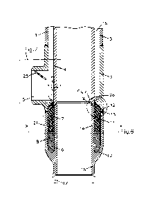
Figure 1 shows a longitudinal cross-sectional view of a preferred
embodiment of a heat exchanger according to the invention. The heat
exchanger comprises a coolable double-wall tube 1 including an inner
tubular wall 4 and an outer tubular wall 3. Said inner tubular wall 4 is
configured to convey said reaction gas to be quenched or coolable. A space 15
defined by said inner tubular wall 4 and said outer tubular wall 3 is
configured to convey a coolant, for example water. Said outer tubular wall 3
of said coolable double-wall tube 1 may for example at least partly be made
of manganese and/or molybdene, or of carbon steel or of any other suitable
material known to the person skilled in the art. The outer tubular wall 3
may have a wall thickness in a range of for example 5-20 mm. The outer
diameter of said coolable double-wall tube may for example be comprised in
a range of 100-200 mm. Said inner tubular 4, having a thickness of for
example 5-14 mm, may for example be made of a steel alloy, for example of
0.5Mo or 1.25Cr-0.5Mo, or of any other suitable material. An outer diameter
CA 03030207 2019-01-08
WO 2018/007452 PCT/EP2017/066790
of an inner tube defined by said inner tubular wall 4 of said double-wall
tube 1 may for example be comprised in a range of 60-140 mm. The heat
exchanger further comprises a tubular connection member 10 having a
bifurcating longitudinal cross-section comprising an exterior wall section 11
5 and an interior wall section 14 defining an intermediate space 21 filled
with
refractory filler material 6, 7. Said tubular connection member may for
example at least partly be made of a steel alloy, for example of 25Cr-35NiNb
or of any other suitable material known to the skilled person. A thickness of
the exterior wall section 11 and of the interior wall section 14 can for
10 .. example be comprised in a range of 7-14 mm. A converging end 16 of said
connection member 10 is arranged to be in connection with an uncoolable
reaction gas conveying pipe 17. Said converging end 16 may for example be
welded 13 to said gas conveying pipe 17, or connected otherwise. The
exterior wall section 11 is connected with said outer tubular wall 3 of said
.. coolable double-wall tube 1, for example directly via a weld, or for
example
indirectly via an intermediate coolant box 2 as in Figure 1. An internal
diameter of said connection member 10 can be equal to, or slightly (<2 mm)
smaller than, an internal diameter of an inner tube defined by said inner
tubular wall 4 of said double-wall tube 1. An axial gap 27 is left between
said interior wall section 14 and said inner tubular wall 4 of said coolable
double-wall tube 1. The heat exchanger also includes a sealing member 9
configured to seal said axial gap 27 between said interior wall section 14
and said inner tubular wall 4 of said coolable double-wall tube 1. The
coolable double-wall tube 1 of the heat exchanger can further include a
coolant inlet nozzle 5 arranged to let a coolant into said space defined by
said inner tubular wall 4 and said outer tubular wall 3 of said coolable
double-wall tube 1 at a bottom level of said coolable double-wall tube 1 close
to said tubular connection member. The inlet nozzle 5 may reach into the
outer tubular wall 3 of the double-wall tube 1 tangentially or radially. An
.. inner diameter of such a coolant inlet nozzle 5 may for example be
CA 03030207 2019-01-08
WO 2018/007452 PCT/EP2017/066790
11
comprised in a range of 60-125 mm. In the embodiment of Figure 1, said
coolant inlet nozzle 5 is included in a coolant box 2 extending between said
outer tubular wall 3 of said coolable double-wall tube 1 and said exterior
wall section 11 of said tubular connection member 10 and surrounding said
inner tubular wall 4 of said coolable double-wall tube 1. The coolant box 2,
with an outer diameter in a range of for instance 110-220 mm, may for
example be made of carbon steel, or of an alloy as for example of 1.25Cr-
0.5Mo, or of any other suitable material. The coolant box 2 may for example
be welded 13 to said outer tubular wall 3 and to said exterior wall section
11, for example via a cylindrical extension 12 of said coolant box 2, or may
be connected otherwise. The coolant box 5 may also be fixedly connected, for
example welded 13, to the inner tubular wall 4 at a bottom level of said
double-wall tube 1. The coolant box 2 may have a reinforced outer shell with
a thickness for example in a range of 10-24 mm, which may be thicker than
a thickness of the exterior wall section 11 or of the outer tubular wall 3,
but
this need not be the case.
Figures 2 and 3 show an enlargement of the encircled area in
Figure 1, and representing a more detailed view of the area where the
interior wall section 14 of the tubular connection member 10 meets the
inner tubular wall 4 of said coolable double-wall tube 1. An axial gap 27 is
left between said interior wall section 14 and said inner tubular wall 4 of
said coolable double-wall tube 1. The sealing member 9 is configured to seal
said axial gap 27 between said interior wall section 14 and said inner
tubular wall 4 of said coolable double-wall tube 1 in order to protect the
refractory filler material 6, 7 in the intermediate space 21 of the tubular
connection member 10 against hot reaction gas leaking into said
intermediate space 21 and damaging said refractory filler material 6, 7.
With the aim of improving said protective sealing of the intermediate space
21 over all temperature ranges of the cooling process, an edge of said inner
tubular wall 4 engaging said sealing member 9 comprises in an inventive
CA 03030207 2019-01-08
WO 2018/007452 PCT/EP2017/066790
12
way an at least partly bevelled edge including a bevel 18 engaging said
sealing member 9. In the preferred embodiment shown in Figures 2 and 3,
said edge of said inner tubular wall 4 is bevelled radially inwardly, such
that the sealing member 9 can be reached from an inside of the tubular
connection member 10 and/or from the coolable double-wall tube 1. Also an
edge of said interior wall section 14 engaging said sealing member 9 can
comprise a partly bevelled edge including a bevel 19 radially spaced apart
by a radial gap 20 from, and substantially in parallel with, said at least
partly bevelled edge of said end side of said inner tubular wall 4, as shown
in Figures 2 and 3. Furthermore, the sealing member 9 engages an
unbevelled part of said partly bevelled edge of said interior wall section 14
of said tubular connection member 10. In an unheated state of the heat
exchanger, depicted in Figure 2, the intermediate space 21 is thus sealed by
the sealing member 9 only. Due to heating caused by the passing of the hot
.. reaction gas to be quenched, the various parts of the heat exchanger will
all
be expanding, but this thermal expansion is dependent on the proximity and
exposure to the hot reaction gas. The interior wall section 14 will for
example be axially and radially expanding more than the inner tubular wall
4. The position of the sealing member 9 is therefore going to change slightly
during thermal expansion, as shown in Figure 3: the sealing member 9 will
be slightly shifted along the bevel 18 of the inner tubular wall 4, and will
also be slightly shifted radially inwardly on the unbevelled part of the
partly
bevelled edge of said interior wall section 14 of the tubular connection
member 10. Due to the radial thermal expansion of the interior wall section
14 of said tubular connection member 10, the bevel 19 of the partly bevelled
edge of the tubular connection member 10 will be engaging the bevel 18 of
the at least partly bevelled edge of the inner tubular wall 4, thus forming a
second protective sealing of the refractory filler material 6, 7 in the
intermediate space 21 of the tubular connection member 10.
CA 03030207 2019-01-08
WO 2018/007452 PCT/EP2017/066790
13
Figure 4 shows a preferred embodiment of a sealing member 9 of
the heat exchanger of Figure 1. The sealing member 9 comprises thinned
ends 9a, 9b, which can be joint to form a ring structure with slidingly
overlapping thinned ends 9a, 9b, shown in more detail in Figure 5
representing an enlargement of the framed area in Figure 4. The length of
the thinned ends 9a, 9b are arranged to provide a minimal and initial
overlap L3 to guarantee a sealing function at the start-up of the cooling
process before any thermal expansion takes place. The thinned ends 9a, 9b,
in particular the length L2, are also arranged to allow for circumferential
thermal expansion of the sealing member 9 itself. Due to the confinement of
the sealing member 9 between the coolable double-wall tube 1 and the
tubular connection member 10, thermal expansion of the ring will
substantially be limited to circumferential expansion. The sealing member 9
preferably also comprises a spring-like element arranged to press said
sealing member 9 against said at least partly bevelled edge of said inner
tubular wall 4. The sealing member 9 can for instance be made of a high
nickel alloy, for example an alloy comprising iron, chromium and nickel,
such as UNS N08330 or DIN 1.4886 or any other material known to the
person skilled in the art.
Figure 6 shows a transverse cross-sectional view according to line
X-X in Figure 1 of the refractory filler material 6, 7 in the intermediate
space 21 of the tubular connection member 10, the refractory filler material
6, 7 having a thickness in a range of for instance 15-25 mm in a radial
direction. As can be seen in Figure 1, said refractory filler material 6, 7
can
comprise in an axial direction at least two layers 6 and 7 of refractory
filler
material with different heat conductivity. The heat conductivity of said at
least two layers of refractory filler material preferably decreases towards
said coolable double-wall tube 1. The first layer of refractory filler
material 6
may for example be a layer of dense refractory filler material with a high
thermal conductivity, for example a layer of silicon carbide or of any other
CA 03030207 2019-01-08
WO 2018/007452 PCT/EP2017/066790
14
suitable material with a heat conductivity coefficient of for instance 8-12
W/(m2 K), and the second layer may comprise a soft insulating filler 7, for
example a layer of Superwool PlusTM, or of any other suitable material
with a heat conductivity coefficient of for instance 0.05-0.2 W/(m2 K). In an
innovating way, the refractory filler material 6, 7 of the preferred
embodiment in Figure 6 comprises three sectors 26 of refractory filler
material separated by three slits 22 extending in an axial and a radial
direction. The refractory material may also comprise two or four or more
sectors 26 and slits 22. The slits 22 may for example be separated by 1800
,
120 , or 90 , or by any other angle. The slits 22 can have a width of for
instance 1-2 mm. The sectors 26 may, but need not, be equally partitioned.
The at least two slits 22 may for example comprise air, or may comprise a
layer of ceramic paper, in order to absorb thermal expansion differences in a
radial and circumferential direction between the refractory filler material 6,
7 and a more expanding interior wall section 14 pushing said refractory
filler material 6, 7 against a less expanding exterior wall section 11 of said
tubular connection member 10. As represented in Figure 1, a layer of
ceramic paper 8 may also be comprised between said refractory filler
material 6 and said exterior wall section 11 of said tubular connection
member 10. This thin layer of ceramic paper 8, having a thickness of for
example 0.5-1.0 mm and a heat conductivity coefficient in a range of for
example 0.05-1.0 W/(m2 K), may enclose only part of the refractory filler
material, for example only a first axial layer 6 of the refractory filler
material, as in Figure 1, or may encompass the refractory filler material
over the entire axial length of the intermediate space 21.
Figure 7 shows an enlargement of a framed area in Figure 1,
representing the coolant inlet nozzle 5 arranged to let coolant, for example
water, into the space defined by the inner tubular wall 4 and said outer
tubular wall 3 of said coolable double-wall tube 1. Figure 8 shows a
schematic front view in an axial direction of the coolant inlet nozzle 5 of
the
CA 03030207 2019-01-08
WO 2018/007452 PCT/EP2017/066790
heat exchanger of Figure 1. In this preferred embodiment, the coolant inlet
nozzle 5 is included in a coolant box 2 surrounding said inner tubular wall 4
of said coolable double-wall tube 1. In Figure 7, the coolant box 2 has a
thicker, reinforced outer shell than a thickness of the outer tubular wall 3,
5 but this need not be the case. The heat exchanger comprises at least one
baffle 23, 24, 25 arranged to guide a flow of coolant in said space defined by
said inner tubular wall 4 and said outer tubular wall 3 of said coolable
double-wall tube 1, thus preventing coolant flow stagnation and under
deposit corrosion, in particular in an area 28 (see Figure 1) at a bottom
level
10 of the coolable double wall-tube 1 opposite said at least one baffle 23,
24, 25,
which area 28 is particularly vulnerable for under deposit corrosion. Said at
least one baffle 23, 24, 25 may for example be fixedly connected with an
inside of the outer tubular wall 3, or with an inside of the coolant inlet
nozzle, as is the case for baffle 25. Preferably, at least one baffle is
fixedly
15 connected with an outside of said inner tubular wall 4 of said coolable
double-wall tube 1, as are for example baffles 23 and 24. Baffle 25 extends
into the coolant inlet nozzle 5 directing coolant towards a bottom level of
the
coolable double wall-tube 1. Baffles 23 and 24 are located within the coolant
space between the outer and the inner tubular walls 3 and 4 and preferably
extend into a direction of said coolant inlet nozzle 5. The at least one
baffle
23, 24, 25 may for example be a baffle plate, which may include holes or be a
closed plate. Baffle plates 23,24, 25 may have a constant or variable height,
and may include various shapes, such as rectangular, trapezoidal, partially
bevelled, or preferably L-shaped baffle plates (see Figure 9). The at least
one
baffle may partly extend in a circumferential direction around the inner
tubular wall 4, or be limited to a coolant entrance area close to or facing
the
coolant inlet nozzle 5. The depicted advantageous embodiment of Figures 7
and 8 comprises at least two mutually transversally positioned baffles 23
and 24. Baffle 24 is positioned in parallel with a central axis of the coolant
inlet nozzle 5 directing coolant to a bottom level of the coolable double wall-
CA 03030207 2019-01-08
WO 2018/007452 PCT/EP2017/066790
16
tube 1. Baffle 23 is positioned transversally with respect to baffle 24,
separating the flow of coolant in a clockwise and an anti-clockwise rotating
flow around the inner tubular wall 4. As best seen in Figure 8, said at least
one baffle 23, 24, 25 is preferably off-centered with respect to a central
axis
of said coolant inlet nozzle 5. The off-centered position of said baffle 23,
24,
25 improves the circulation and thus the efficiency of the coolant around the
bottom level of the double-wall tube 1, where coolant is most needed. The at
least one baffle 23, 24, 25 can for example be made of carbon steel, or of any
other suitable material as known to the person skilled in the art.
For the purpose of clarity and a concise description, features are
described herein as part of the same or separate embodiments, however, it
will be appreciated that the scope of the invention may include
embodiments having combinations of all or some of the features described.
It may be understood that the embodiments shown have the same or similar
components, apart from where they are described as being different.
In the claims, any reference signs placed between parentheses
shall not be construed as limiting the claim. The word 'comprising' does not
exclude the presence of other features or steps than those listed in a claim.
Furthermore, the words 'a' and 'an' shall not be construed as limited to 'only
one', but instead are used to mean 'at least one', and do not exclude a
plurality. The mere fact that certain measures are recited in mutually
different claims does not indicate that a combination of these measures
cannot be used to an advantage. Many variants will be apparent to the
person skilled in the art. All variants are understood to be comprised within
the scope of the invention defined in the following claims.