Note: Descriptions are shown in the official language in which they were submitted.
84999541
MULTI-PHASE HEAT DISSIPATING DEVICE EMBEDDED IN
AN ELECTRONIC DEVICE
CROSS-REFERENCE TO RELATED APPLICATION
[0001] This application claims priority to and the benefit of Non-
Provisional
Application No. 15/236,070 filed in the U.S. Patent and Trademark Office on
August 12, 2016.
BACKGROUND
Field
[0002] Various features relate a heat dissipating device, and more
specifically to a
multi-phase heat dissipating device embedded in an electronic device.
Background
[0003] Electronic devices include internal components that generate
heat. Some of
these internal components include a central processing unit (CPU), a graphics
processing unit (GPU) and/or memory. Some of these internal components can
generate
a lot of heat. Specifically, a high performance CPU and/or GPU of an
electronic device
can generate a lot of heat, especially when performing data intensive
operations (e.g.,
games, processing video).
[0004] To counter or dissipate the heat generated by the CPU and/or GPU,
an
electronic device may include a heat dissipating device, such as a heat
spreader. FIGS.
1-3 illustrate an example of a mobile device that includes a heat spreader for
dissipating
heat generated by a chip. As shown in FIGS. 1 and 2, the mobile device 100
includes a
display 102, a back side surface 200, a die 202, and a heat spreader 204. The
die 202
and the heat spreader 204, which are both shown with dotted lines, are located
inside the
mobile device 100. The die 202 is coupled to a first surface of the heat
spreader 204. A
second surface of the heat spreader 204 is coupled to a first surface (e.g.,
inner surface)
of the back side surface 200.
[0005] FIG. 3 illustrates a profile view of the mobile device 100 that
includes the
heat spreader 204. As shown in FIG. 3, the mobile device 100 includes the
display 102,
the back side surface 200, a front side surface 300, a bottom side surface
302, and a top
Date Recue/Date Received 2020-10-26
CA 03031256 2019-01-17
WO 2018/031218
PCMJS2017/043253
2
side surface 304. FIG. 3 also illustrates a printed circuit board (PCB) 306,
the die 202
and the heat spreader 204 inside the mobile device 100.
[0006] As further
shown in FIG. 3. a first side of the die 202 is coupled to a first
surface of the PCB 306. A second side of the die 202 is coupled to a first
surface of the
heat spreader 204. A second surface of the heat spreader 204 is coupled to a
first surface
(e.g., inner surface) of the back side surface 200. In this configuration, a
lot of the heat
that is generated by the die 202 is dissipated through the heat spreader 204
and the back
side surface 200 of the mobile device. However, the heat spreader 204 has
limitation,
including its limited heat dissipating capabilities. For example, the heat
spreader 204
implemented in a mobile device, may be limited to dissipate away about 3 Watts
of heat
(depending of the configuration of the heat spreader 204).
[0007] Therefore,
there is a need for an improved method and design for efficiently
dissipating heat from an electronic device (e.g., mobile device), while at the
same time
keeping the temperature of the outer surface of the electronic device within a
threshold
that is acceptable to a user of the electronic device. In addition, there is a
need for
reducing the junction temperature of heat generating region.
SUMMARY
[0008] Various
features relate a heat dissipating device, and more specifically to a
multi-phase heat dissipating device for an electronic device.
[0009] An example
provides a device that includes a region comprising an
integrated device and a heat dissipating device coupled to the region
comprising the
integrated device. The heat dissipating device is configured to dissipate heat
away from
the region. The heat dissipating device includes a fluid, an evaporator
configured to
evaporate the fluid, a first condenser configured to condense the fluid, where
the first
condenser is located in a first wall of the device, an evaporation portion
coupled to the
evaporator and the first condenser, and a collection portion coupled to the
first
condenser and the evaporator. The evaporation portion is configured to channel
an
evaporated fluid from the evaporator to the first condenser. The collection
portion is
configured to channel a condensed fluid from the first condenser to the
evaporator.
[0010] Another
example provides a device that includes a region comprising an
integrated device and a heat dissipating means coupled to the region
comprising the
integrated device. The heat dissipating means is configured to dissipate heat
away from
the region. The heat dissipating means includes a fluid, an evaporator means
configured
84999541
3
to evaporate the fluid, a first condenser means configured to condense the
fluid, where the
condenser means is located in a first wall of the device, an evaporation
portion coupled to the
evaporator means and the first condenser means, and a collection portion
coupled to the first
condenser means and the evaporator means. The evaporation portion is
configured to channel
an evaporated fluid from the evaporator means to the first condenser means.
The collection
portion is configured to channel a condensed fluid from the condenser means to
the evaporator
means.
[0010a] According to one aspect of the present invention, there is provided an
apparatus
comprising: a region comprising an integrated device; and a heat dissipating
means coupled to
the region comprising the integrated device, the heat dissipating means
implemented in at least
a first wall of the apparatus, the heat dissipating means is configured to
dissipate heat away
from the region, wherein the heat dissipating means comprises: a fluid; an
evaporator means
configured to evaporate the fluid; a first condenser means configured to
condense the fluid,
wherein the first condenser means is located in the first wall of the
apparatus; an evaporation
portion coupled to the evaporator means and the first condenser means, the
evaporation portion
configured to channel an evaporated fluid from the evaporator means to the
first condenser
means; and a collection portion coupled to the first condenser means and the
evaporator means,
the collection portion configured to channel a condensed fluid from the first
condenser means
to the evaporator means, wherein the collection portion is located in at least
another wall of the
apparatus.
DRAWINGS
[0011] Various features, nature and advantages may become apparent from the
detailed
description set forth below when taken in conjunction with the drawings in
which like reference
characters identify correspondingly throughout.
[0012] FIG. 1 illustrates a front view of a mobile device.
[0013] FIG. 2 illustrates a back view of a mobile device that includes a
heat spreader.
[0014] FIG. 3 illustrates a profile view of a mobile device that includes a
heat spreader.
[0015] FIG. 4 illustrates a view of a heat dissipating device.
Date Recue/Date Received 2020-10-26
84999541
3a
[0016] FIG. 5 illustrates a view of the heat dissipating device with
respect to a mobile device
wall.
[0017] FIG. 6 illustrates a plan view of a heat dissipating device.
[0018] FIG. 7 illustrates a profile view of a heat dissipating device.
[0019] FIG. 8 illustrates another profile view of a heat dissipating
device.
[0020] FIG. 9 illustrates a view of another heat dissipating device.
[0021] FIG. 10 illustrates a view of the heat dissipating device with
respect to a mobile
device wall.
[0022] FIG. 11 illustrates a plan view of another heat dissipating device.
[0023] FIG. 12 illustrates a view of a heat dissipating device.
[0024] FIG. 13 illustrates a view of the heat dissipating device with
respect to a mobile
device wall.
[0025] FIG. 14 illustrates a plan view of a heat dissipating device.
[0026] FIG. 15 illustrates a profile view of a heat dissipating device.
[0027] FIG. 16 illustrates a profile view of another heat dissipating
device.
[0028] FIG. 17 illustrates a profile view of another heat dissipating
device.
Date Recue/Date Received 2020-10-26
CA 03031256 2019-01-17
WO 2018/031218
PCT[US2017/043253
4
[0029] FIG. 18 illustrates a profile view of another heat dissipating
device.
[0030] FIG. 19 illustrates an angled view of a thermally conductive
element that is
configured as an evaporator.
[0031] FIG. 20 illustrates an angled view of a thermally conductive
element that is
configured as a condenser.
[0032] FIG. 21 (which includes FIGS. 21A-21B) illustrates a sequence for
fabricating a thermally conductive element.
[0033] FIG. 22 illustrates an exemplary flow diagram of a method for
fabricating a
heat dissipating device.
[0034] FIG. 23 illustrates a view of a heat dissipating device comprising
walls for
providing structural support.
[0035] FIG. 24 illustrates a view of a heat dissipating device comprising
walls for
providing structural support.
[0036] FIG. 25 illustrates various electronic devices that may integrate a
heat
dissipating device, a semiconductor device, an integrated device, a die, an
integrated
circuit, a PCB and/or a multi-layer heat spreader described herein.
DETAILED DESCRIPTION
[0037] In the following description, specific details are given to provide a
thorough
understanding of the various aspects of the disclosure. However, it will be
understood
by one of ordinary skill in the art that the aspects may be practiced without
these
specific details. For example, circuits may or may not be shown in block
diagrams in
order to avoid obscuring the aspects in unnecessary detail. In other
instances, well-
known circuits, structures and techniques may not be shown in detail in order
not to
obscure the aspects of the disclosure.
Overview
[0038] Some implementations provide a device (e.g., mobile device) that
includes a
region comprising an integrated device (e.g., chip, die), and a heat
dissipating device
coupled to the region comprising the integrated device. The heat dissipating
device may
be a multi-phase heat dissipating device. The heat dissipating device is
configured to
dissipate heat away from the region. The heat dissipating device includes a
fluid, an
evaporator configured to evaporate the fluid, a condenser configured to
condense the
fluid, where the condenser is located in a wall of the device, an evaporation
portion
CA 03031256 2019-01-17
WO 2018/031218
PCT/US2017/043253
coupled to the evaporator and the condenser, and a collection portion coupled
to the
condenser and the evaporator. The evaporation portion is configured to channel
an
evaporated fluid from the evaporator to the condenser. The collection portion
is
configured to channel a condensed fluid from the condenser to the evaporator.
In some
implementations, the region may include a thermal interface material (TIM)
coupled to
the integrated device and the heat dissipating device. In some
implementations, the
region is a heat generating region configured to generate heat when the device
(e.g.,
mobile device) is operational.
Exemplary Multi¨Phase Heat Dissipating Device
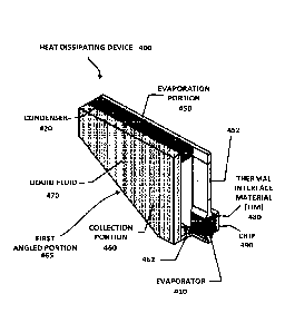
[0039] FIG. 4
illustrates a heat dissipating device 400 that includes an evaporator
410, a condenser 420, an evaporation portion 450, an evaporation portion 452,
a
collection portion 460, a collection portion 462 and a fluid 470. The
evaporator 410 may
be an evaporator means (e.g., means for evaporating). The condenser 420 may be
a
condenser means (e.g., means for condensing). The collection portion 460
includes at
least one angled portion 465 (e.g., non-orthogonal angled portion). As will be
further
described below, the at least one angled portion 465 is configured to help
direct fluid
towards the evaporator 410 (e.g., through gravity).
[0040] In some
implementations, the heat dissipating device 400 (e.g., heat
dissipating means, means for dissipating heat) is a multi-phase heat
dissipating device.
As will be further described below, the heat dissipating device 400 may be a
cooling
device that provides heat dissipation through recirculation of a fluid (e.g.,
fluid 470)
without the need of a pump or compressor.
[0041] The
evaporator 410 is coupled to the evaporation portion 452 and the
collection portion 462. The evaporation portion 452 is coupled to the
evaporation
portion 450. In some implementations, the evaporation portion 450 and the
evaporation
portion 452 may be considered as one evaporation portion.
[0042] The
condenser 420 (e.g., first condenser, first condenser means, first means
for condensing) is coupled to the evaporation portion 450 and the collection
portion
460. The collection portion 460 is coupled to the collection portion 462. In
some
implementations, the collection portion 460 and the collection portion 462 may
be
considered as one collection portion.
[0043] FIG. 4
illustrates the fluid 470 is located inside the heat dissipating device
400. The fluid 470 is configured to flow inside the heat dissipating device
400. In some
CA 03031256 2019-01-17
WO 2018/031218
PCT[US2017/043253
6
implementations, the flow of the fluid 470 inside the heat dissipating device
400 allows
for the efficient heat transfer from one portion of the heat dissipating
device 400 to
another portion of the heat dissipating device 400. For example, the fluid 470
may be
configured to allow heat to transfer or flow from the evaporator 410 to the
condenser
420. Thus, heat (e.g., from heat generating region, integrated device) coming
in through
the evaporator 410 may be released through the condenser 420 in some
implementations. The larger the size of the condenser 420, the better the
cooling of the
integrated device 490.
[0044] FIG. 4
illustrates that the fluid 470 is located in the collection portion 460 of
the heat dissipating device 400. However, in some implementations, the fluid
470 may
be located in other portions (e.g., the evaporator 410, the condenser 420, the
evaporation
portion 450, the evaporation portion 452, the collection portion 462) of the
heat
dissipating device 400. For example, the fluid 470 may travel through the
evaporator
410, the evaporation portion 452, the evaporation portion 450, the condenser
420, the
collection portion 460, and the collection portion 462. Although not shown,
each of the
evaporator 410, the condenser 420, the evaporation portion 450, the
evaporation portion
452, the collection portion 460, and the collection portion 462 includes one
or more
cavities, or one or more space (e.g., internal space) that allows the fluid
470 to flow in
the heat dissipating device 400.
[0045] The fluid
470 may have different phases, including a liquid phase and a gas
phase. In some implementations, the fluid 470 may be a combination of a liquid
phase
and a gas phase. In some implementations, a vapor phase of the fluid 470 may
be a
combination of a liquid phase and a gas phase. In some implementations, the
temperature at which the fluid changes from a liquid phase to a gas phase is
referred to
as the boiling temperature of the fluid. In some implementations, the fluid
470 has a
boiling temperature of about 40 Celsius or less (boiling temperature will vary
based on
the type of fluid or refrigerant used). In some implementations, the fluid 470
may be in
different phases in different portions of the heat dissipating device 400.
[0046] The fluid
(e.g., fluid 470) may be provided in the heat dissipating device
through a cavity (e.g., hole) formed in the heat dissipating device. After the
fluid is
provided through the cavity (not shown), the cavity is sealed to create a
sealed (e.g.,
hermetically sealed) heat dissipating device. The cavity may be formed in
different
portions of the heat dissipating device (e.g., heat dissipating device 400).
For example,
the cavity and seal may be formed in the collection portion (e.g., collection
portion 460,
CA 03031256 2019-01-17
WO 2018/031218
PCT/US2017/043253
collection portion 462) and/or the evaporation portion (e.g., evaporation
portion 450,
evaporation portion 452).
[0047] A more
detailed example of how the fluid 470 may flow in the heat
dissipating device 400, how heat may be dissipated and/or transferred, and the
different
phases of the fluid 470 are further described and illustrated below in FIG. 6.
[0048] FIG. 5
illustrates an example of how a heat dissipating device 400 may be
implemented inside a device 500. For purpose of clarity, only a portion of the
device
500 is shown in FIG. 5. The device 500 (e.g., mobile device) includes a wall
510 (e.g.,
first wall) and a wall 520 (e.g., second wall). In some implementations, the
wall 520 is
the back wall (e.g., back surface) of the device 500. In some implementations,
the wall
520 is located opposite to the display and/or screen of the device 500. For
the purpose
of clarity, two walls are shown for the device 500. However, the device 500
and/or other
devices in the present disclosure may include more walls (e.g., first wall,
second wall,
third wall, fourth wall, fifth wall, sixth wall).
[0049] As shown in
FIG. 5, the evaporation portion 450 and the condenser 420 are
located in the wall 510. In particular, the evaporation portion 450 and the
condenser 420
are embedded in the wall 510 (e.g., first wall). The condenser 420 has a size
that is as
large as possible to maximize the cooling capacity of the integrated device
490. The
collection portion 460 is located in the wall 520. In particular, the
collection portion 460
is embedded in the wall 520 (e.g., second wall). It is noted that parts of the
collection
portion 460 may be located in the wall 510. In some implementations, the
collection
portion 460 is located in the wall (e.g., wall 520) that is opposite to the
side of the
device 500 that includes a screen or display. FIG. 5 illustrates that the
evaporator 410 is
located inside the device 500. However, in FIG. 5, the evaporator 410 is not
embedded
in the walls of the device 500. For example, in some implementations, the
evaporator
410 is not part of the wall of the device 500. In addition, the evaporation
portion 452
and the collection portion 462 are located inside the device 500. However, the
evaporation portion 452 and the collection portion 462 are not embedded in the
walls of
the device 500. However, in some implementations, the evaporation portion 452
and/or
the collection portion 462 may be embedded in one or more walls (e.g., wall
510, wall
520) of the device 500.
[0050] In some
implementations, the heat dissipating device 400 is a heat
dissipating means configured to be coupled to a region (e.g., heat generating
region) of a
device (e.g., mobile device) that generates heat. The heat generating region
may include
CA 03031256 2019-01-17
WO 2018/031218
PCT/US2017/043253
8
an integrated device (e.g., die, chip, package, central processing unit (CPU),
graphical
processing unit (GPU)). The heat generating region may also include a thermal
interface
material (TIM) that is coupled to the integrated device.
[0051] As shown in
FIGS. 4 and 5, the heat dissipating device 400 may be coupled
to an integrated device 490 (e.g., die, chip, package, central processing unit
(CPU),
graphical processing unit (GPU)) through an optional thermal interface
material (TIM)
480. The thermal interface material (TIM) 480 may be a thermally conductive
adhesive
that couples the heat dissipating device 400 to the integrated device 490. The
thermal
interface material (TIM) 480 may include good thermal conductivity properties
so that
heat generated from the integrated device 490 may thermally conduct to the
heat
dissipating device 400.
[0052] The heat
dissipating device 400 is coupled to the integrated device 490 and
the thermal interface material (TIM) 480 such that the evaporator 410 is
coupled to the
integrated device 490 and the thermal interface material (TIM) 480.
[0053] As shown in
FIGS. 4 and 5, heat from the integrated device 490 thermally
conducts through the thermal interface material (TIM) 480 and to the
evaporator 410.
The evaporator 410 is thus heated, which in turns heats the fluid 470 (which
is in liquid
phase) from the collection portion 460 and/or the collection portion 462. The
fluid 470
that is heated from the evaporator 410 turns into a gas phase or a vapor
phase, and then
travels from the evaporator 410 through the evaporation portion 452 and/or the
evaporation portion 450, and to the condenser 420.
[0054] When the
fluid 470 (which is in a gas phase or vapor phase) reaches the
condenser 420, heat is transferred away from the fluid 470 through the
condenser 420,
and escapes out of the heat dissipating device 400. Once the fluid 470 passes
through
the condenser 420, it returns to liquid phase (e.g., or at least partially
liquid phase) into
the collection portion 460 and/or the collection portion 462. Thus, in some
implementations, as the fluid 470 travels through the heat dissipating device
400, the
fluid 470 may travel inside at least some of the walls (e.g., wall 510, wall
520) of the
device 500. For optimal cooling, it is desirable to condense all the
evaporated fluid
(e.g., vapor) coming from the evaporator 410, thus the desirability to
maximize the size
of the condenser 420.
[0055] The heat
dissipating device 400 may have different configurations. In some
implementations, portions of the heat dissipating device 400 may be exposed to
an
external environment of the device 500 (e.g., condenser 420 may be exposed).
CA 03031256 2019-01-17
WO 2018/031218
PCT[US2017/043253
9
[0056] As shown in
FIGS. 4 and 5 and the present disclosure, the condenser 420 has
a bigger size (e.g., bigger volume) than the evaporator 410. In some
implementations,
this is done to spread out the heat over a bigger area so has to prevent the
device from
reaching a critical temperature. In addition, the condenser 420 may have a
bigger size
than the evaporator 410 to help fully condense the vapors (e.g., evaporated
fluid)
coming from the evaporator 410. For example, the size of the condenser 420 may
be
selected so that the heat dissipating device 400 dissipates as much heat as
possible while
still keeping a surface temperature of the device to be less than an
acceptable for a user
of the device (e.g., mobile device). Thus, by making the condenser 420 larger
(e.g.,
larger surface area) than the evaporator 410, it ensures that the condenser
420 can
effectively dissipate the heat through the evaporator while keeping the
surface
temperature of the device below a threshold temperature and help fully
condense the
vapors. In addition, by making the condenser 420 larger than the evaporator
410, it
helps prevent dry out in the heat dissipating device 400. Dry out occurs when
the
condenser 420 is not capable of dissipating heat fast enough, thus is not able
to fully
convert the vapors into condensate liquid, causing the incomplete condensation
of the
vapors coming from the evaporator, and thus limiting the cooling capacity of
the device
and after a few cycles will lead to all vapor and no liquid leading to dry out
and device
failure. When dry out occurs, the fluid inside the heat dissipating device
does not flow,
resulting in no recirculation of the fluid in the heat dissipating device 400.
FIG. 6 below
illustrates a more detailed example of how a fluid may flow inside a heat
dissipating
device to provide heat dissipation of heat generating region and/or a region
comprising
an integrated device.
Exemplary Heat Flow of Heat Dissipating Device
[0057] FIG. 6
illustrates a fluid flow of the fluid in the heat dissipating device.
More, specifically, FIG. 6 illustrates how the fluid flow inside the heat
dissipating
device 400 provides efficient heat dissipation of a region comprising an
integrated
device. The heat dissipating device 400 provides a cooling device that is
capable of
recirculating the fluid without the need of a pump or compressor. In some
implementations, the recirculation of the fluid inside the heat dissipating
device 400 is
aided by gravity. Gravity helps improve the heat dissipating capabilities of
the heat
dissipating device 400 and allows the heat dissipating device 400 to work
properly. The
heat dissipating device 400 may be designed in such a way as to perform better
in
CA 03031256 2019-01-17
WO 2018/031218
PCT[US2017/043253
to
certain orientations (e.g., horizontal orientation of the device, vertical
orientation of the
device). In some implementations, the optimal orientation of the heat
dissipating device
400 is one where the evaporator 410 is positioned lower than the condenser
420, and
gravity helps fluid flow from the condenser 420, through the collection
portion 460 and
towards the evaporator 410.
[0058] As mentioned
above, the collection portion 460 includes at least one angled
portion 465. The at least one angled portion 465 may include a non-orthogonal
angled
portion. The non-orthogonal angled portion is configured, with the help of
gravity, to
direct the condensed fluid towards the evaporator 410 (e.g., evaporating
means, means
for evaporating). In some implementations, the collection portion 460 may
include one
or more non-orthogonal angled portions. A non-orthogonal portion may include
different angles. A non-orthogonal portion is a portion (e.g., wall) that
includes a non-
right angled portion (e.g., wall) relative to an edge of the heat dissipating
device 400.
[0059] FIG. 6
illustrates the fluid 470 in the collection portion 460 of the heat
dissipating device 400. The collection portion 460 has at least one angled
portion (e.g.,
first angled portion) so that the fluid 470 (which is in liquid form) flows
down (e.g., due
to gravity) towards the collection portion 462 and the evaporator 410. It is
noted that the
collection portion 460 and the collection portion 462 may be considered as one
collection portion. The evaporator 410 is being heated by a heat generating
region (e.g.,
region comprising TIM and/or integrated device).
[0060] As the fluid
470 enters the evaporator 410 and travels through the evaporator
410, the fluid 470 becomes an evaporating fluid 610 due to the heat from heat
source
(e.g., integrated device) that is passed through the evaporator 410. The
evaporator 410 is
configured so that the pressure drop between the fluid entering the evaporator
410 and
the fluid exiting the evaporator 410 is about 0.0049 bar or less. In some
implementations, the pressure drop across the evaporator 410 needs to be below
0.0049
bar so that the fluid is not blocked from passing through the evaporator 410,
which
would block the recirculation of the fluid in the heat dissipating device 400.
The above
values are merely exemplary. Different designs may have different values.
[0061] Once the
evaporating fluid 610 exits the evaporator 410, the evaporating
fluid 610 becomes an evaporated fluid 620 (e.g., vapor fluid) that travels
through the
evaporation portion 452 and the evaporation portion 450 towards the condenser
420. It
is noted that the evaporation portion 450 and the evaporation portion 452 may
be
CA 03031256 2019-01-17
WO 2018/031218
PCT[US2017/043253
11
considered as one evaporation portion. The evaporated fluid 620 may include
fluid in a
gas phase and some fluid in liquid phase.
[0062] As the
evaporated fluid 620 enters the condenser 420 (which may be located
in the wall 510 of the device) and travels through the condenser 420, the
evaporated
fluid 620 becomes a condensing fluid 630. This process takes heat away from
the
evaporated fluid 620 and through the condenser 420. The heat from the
condenser 420
then escapes out of the heat dissipating device 400 (e.g., out of the device
500 into an
external environment).
[0063] In some
implementations, the condenser 420 is configured so that the
pressure drop between the fluid entering the condenser 420 and the fluid
exiting the
condenser 420 is about 0.0002 bar or less. In some implementations, the
pressure drop
across the condenser 420 needs to be below 0.0002 bar so that the fluid is not
blocked
from travelling through the condenser 420, which would block the recirculation
of the
fluid in the heat dissipating device 400.
[0064] Once the
condensing fluid 630 exits of the condenser 420, the condensing
fluid 630 returns to the collection portion 460 (which may be located in the
wall 520 of
the device 500) as the fluid 470, in liquid phase, and the cycle repeats
itself (e.g., there
is recirculation of the fluid).
[0065] FIG. 6
illustrates how the heat dissipating device 400 uses recirculation of a
fluid to achieve heat dissipation and cooling without the need of a pump or
compressor
to move the fluid, using gravity, to return the condensed fluid, back to the
evaporator
410. In some implementations, fluid recirculation in the heat dissipating
device 400 is
possible through the use of the various designs and/or components of the heat
dissipating device 400. In some implementations, it is important that the
evaporated
fluid 620 and the fluid 470 are separated so that there is recirculation of
the fluid in the
heat dissipating device 400 and to prevent vapor and liquid mixing.
[0066] In one
example, the evaporator 410 and the condenser 420 are designed in
such a way as to minimize the pressure drop as the fluid travels across the
evaporator
410 and the condenser 420. The minimizing of pressure drops can be achieved by
selecting appropriate dimensions for the channels in which the fluid travels
through.
Examples of dimensions for the channels for the evaporator 410 and the
condenser 420
are described below in at least FIGS. 19-20.
[0067] In another
example, the dimensions of the evaporator 410 and the condenser
420 are selected so as to prevent dry out in the heat dissipating device 400.
As
CA 03031256 2019-01-17
WO 2018/031218
PCT/US2017/043253
12
mentioned above, dry out is when the condenser 420 is not dissipating heat
fast enough
in the heat dissipating device 400 (relative to how fast heat is coming in
from the
evaporator 410), causing the fluid in heat dissipating device 400 to turn into
a gas phase
(with little or no liquid phase). When dry out occurs, little or no
recirculation occurs.
Examples of dimensions for the evaporator 410 and the condenser 420 are
described
below in at least FIGS. 19-20.
[0068] In some
implementations, the heat dissipating device 400 operates optimally
when the heat dissipating device 400 is arranged such that the evaporator 410
is located
lower than the condenser 420, so as to take advantage of gravity pulling the
fluid 470
towards the evaporator 410.
[0069] In some
implementations, fluid recirculation in the heat dissipating device
occurs when the temperature of the fluid is about 40 degree Celsius or higher
(e.g.,
boiling temperature of the fluid). However, fluid recirculation may begin at
different
temperatures for different implementations, various fluids and various
coolants.
[0070] FIG. 7
illustrates a top view of the heat dissipating device 400 implemented
in the device 500. As shown in FIG. 7, the condenser 420 is implemented in the
wall
510 of the device 500 (e.g., mobile device), and the evaporator 410 is located
inside the
device 500. In particular, the condenser 420 is embedded in the wall 510 of
the device
500. The evaporator 410 may be coupled to a heat generating region and/or a
region that
includes an integrated device and/or TIM. The device 500 includes a display
702. The
display 702 is located opposite to the wall 520.
[0071] FIG. 8
illustrates a profile view of the heat dissipating device 400
implemented in the device 500. As shown in FIG. 8, the condenser 420 is
implemented
in the wall 510 of the device 500 (e.g., mobile device), the collection
portion 460 is
implemented inside the wall 520 of the device 500. The wall 520 may be
opposite to the
side or wall of the device that includes a screen or display (e.g., display
702). The
evaporator 410 is located inside the device 500. In particular, the condenser
420 is
embedded in the wall 510 of the device 500, and the collection portion 460 is
embedded
in the wall 520 of the device 500. The evaporator 410 may be coupled to a heat
generating region and/or a region that includes an integrated device and/or
TIM.
Exemplary Materials and Fluids
[0072] The heat
dissipating device 400 and its components may include different
materials. In some implementations, the evaporator 410 and the condenser 420
may
CA 03031256 2019-01-17
WO 2018/031218
PCT[US2017/043253
13
include a thermally conductive material, such as metal, copper, Aluminum,
Aluminum-
Nitride (Ceramic), and/or combination thereof
10073] Table 1
below illustrates exemplary materials and their corresponding
properties for materials that may be used in the heat dissipating device 400,
or any heat
dissipating device described in the present disclosure.
Specific Heat
Material Density (kg /m3) Thermal Conductivity
Value (Watts / m-C) (Joules / kg-C)
Copper 8933 388 385
Aluminum 2707 220 896
Aluminum ¨ Nitride
3320 177 780
(Ceramic)
Table 1 ¨ Exemplary Materials and Properties for components of heat
dissipating device
[0074] A particular
thermal conductivity value of a particular material quantifies
how well or how poorly a particular material conducts heat. Different
implementations
may also use different fluids in the heat dissipating device 400. Table 2
below illustrates
exemplary fluids and their corresponding properties.
Liquid Liquid Specific Heat
Latent Heat
Fluid Density Viscosity
(Joules / kg-
(Joules / kg-K)
(kg /m3) (mPa-s) K)
Refrigerant
1218 202.3 177.8 1424.6
R134a
Refrigerant
1369.8 296.5 145.9 1264.4
R236fa
Refrigerant
1346.6 423.3 190.3 1264.4
R245fa
Refrigerant
1165.5 209.6 167.1 1388.7
R1234ze
Table 2 ¨ Exemplary Fluids and Properties
[0075] In some
implementations, the heat dissipating device 400 may use different
combinations of the materials and/or fluids listed above. However, it is noted
that other
implementations may use different materials and fluids, or combinations
thereof than
the ones listed above.
[0076] The use of
the materials and the design of the heat dissipating device in the
present disclosure allows for effective and efficient heat transfer or heat
removal from a
heat generating region of a device. In some implementations, the evaporator
410 may be
CA 03031256 2019-01-17
WO 2018/031218
PCT[US2017/043253
14
configured to have a maximum heat transfer coefficient of about 32.8 kW/m2k.
In some
implementations, the condenser 420 is configured to have a maximum heat
transfer
coefficient of about 9.27 kW/m2k. However, different implementations may have
different maximum heat transfer coefficients.
[0077] In some
implementations, the evaporator 410 may comprise a critical heat
flux at exit of about 26.9 W/cm2. In some implementations, the heat
dissipating device
400 may be configured to dissipate up to about 18 Watts of heat, which is
substantially
more than the heat spreader 204 (which is rated at about 3 Watts for mobile
devices). In
some implementations, the heat dissipating device 400 may be able to dissipate
the
above mentioned heat while having dimensions that measure about 135 mm (L) x
65
mm (W) x 0.6 mm (H) or less. Thus, given its dimensions, the heat dissipating
device
400 may be implemented in a mobile device to dissipate much more heat than the
heat
spreader 204.
Exemplary Multi-Phase Heat Dissipating Devices
[0078] The heat
dissipating device 400 may have different configurations. FIG. 9
illustrates a heat dissipating device 900 that includes two condensers. The
heat
dissipating device 900 is similar to the heat dissipating device 400 of FIG.
4.
[0079] The heat
dissipating device 900 includes the evaporator 410, the condenser
420 (e.g., first condenser), a condenser 920 (e.g., second condenser, second
condenser
means, first means for condensing), the evaporation portion 450, the
evaporation portion
452, the collection portion 460, the collection portion 462, a collection
portion 960, and
a fluid 470. In some implementations, the additional condenser (e.g.,
condenser 920)
provides improved heat dissipation functionality for the heat dissipating
device 900, and
thus leads to increased cooling capacity of the entire device and system.
[0080] FIG. 10
illustrates an example of how a heat dissipating device 900 may be
implemented inside the device 500. The device 500 (e.g., mobile device)
includes a wall
510 (e.g., first wall) and a wall 520 (e.g., second wall). In some
implementations, the
wall 520 is the back wall of the device 500. In some implementations, the wall
520 is
located opposite to the display and/or screen of the device 500. For the
purpose of
clarity, two walls (e.g., wall 510, wall 520) are shown for the device 500.
However, the
device 500 and/or other devices in the present disclosure may include more
walls (e.g.,
first wall, second wall, third wall, fourth wall, fifth wall, sixth wall).
CA 03031256 2019-01-17
WO 2018/031218
PCT[US2017/043253
[0081] As shown in
FIG. 10, the evaporation portion 450 and the condenser 420 are
located in the wall 510. In particular, the evaporation portion 450 and the
condenser 420
are embedded in the wall 510 (e.g., first wall). The condenser 920 and the
collection
portion 460 are located in the wall 520. In particular, the condenser 920 and
the
collection portion 460 are embedded in the wall 520 (e.g., second wall). The
collection
portion 960 is located in both the wall 510 and the wall 520. In some
implementations,
the condenser 920 and the collection portion 460 are located in the wall
(e.g., wall 520)
that is opposite to the side of the device 500 that includes a screen or
display (e.g.,
display 702). In some implementations, the second condenser (e.g., condenser
920)
provides more heat transfer capabilities and helps better condense the
uncondensed fluid
(e.g., vapor) coming from the condenser 420 (e.g., first condenser). By
placing the
condenser 920 near a surface area of the device 500, improved heat transfer
capabilities
can be achieved.
[0082] The flow of
the fluid 470 in heat dissipating device 900 is similar as in the
heat dissipating device 400.
Exemplary Heat Flow of Heat Dissipating Device
[0083] FIG. 11
illustrates a fluid flow of the fluid in the heat dissipating device.
More, specifically, FIG. 11 illustrates how the fluid flow inside the heat
dissipating
device 900 provides efficient heat dissipation of an integrated device. The
heat
dissipating device 900 provides a cooling device that is capable of
recirculating the fluid
without the need of a pump or compressor. In some implementations, the
recirculation
of the fluid inside the heat dissipating device 900 is aided by gravity.
Gravity helps
improve the heat dissipating capabilities of the heat dissipating device 900
and allows
the heat dissipating device 900 to work properly. The heat dissipating device
900 may
be designed in such a way as to perform better in certain orientations (e.g.,
horizontal
orientation of the device, vertical orientation of the device). In some
implementations,
the optimal orientation of the heat dissipating device 900 is one where the
evaporator
410 is positioned lower than the condenser 420 and the condenser 920 and
gravity helps
fluid flow from the condenser 420 and the condenser 920, through the
collection portion
460 and towards the evaporator 410.
[0084] As mentioned
above, the collection portion 460 includes at least one angled
portion 465. The at least one angled portion 465 may include a non-orthogonal
angled
portion. The non-orthogonal angled portion is configured, with the help of
gravity, to
CA 03031256 2019-01-17
WO 2018/031218
PCT/US2017/043253
16
direct the condensed fluid towards the evaporator 410 (e.g., evaporating
means, means
for evaporating). In some implementations, the collection portion 460 may
include one
or more non-orthogonal angled portions. A non-orthogonal portion may include
different angles. A non-orthogonal portion is a portion (e.g., wall) that
includes a non-
right angled portion (e.g., wall) relative to an edge of the heat dissipating
device 900.
[0085] FIG. 11
illustrates the fluid 470 in the collection portion 460 of the heat
dissipating device 900. At least some of the collection portion 460 may be
implemented
in the wall 520 of the device 500. The collection portion 460 has an angled
portion so
that the fluid 470 (which is in liquid form) flows down (e.g., due to gravity)
towards the
collection portion 462 and the evaporator 410. It is noted that the collection
portion 460
and the collection portion 462 may be considered as one collection portion.
The
evaporator 410 is being heated by a heat generating region (e.g., region
comprising TIM
and/or integrated device).
[0086] As the fluid
470 enters the evaporator 410 and travels through the evaporator
410, the fluid 470 becomes an evaporating fluid 610 due to the heat from heat
source
(e.g., integrated device) that is passed through the evaporator 410. The
evaporator 410 is
configured so that the pressure drop between the fluid entering the evaporator
410 and
the fluid exiting the evaporator 410 is about 0.0049 bar or less. In some
implementations, the pressure drop across the evaporator 410 needs to be below
0.0049
bar so that the fluid is not blocked from travelling through the evaporator
410, which
would block the recirculation of the fluid in the heat dissipating device 900.
Different
implementations may have properties.
[0087] Once the
evaporating fluid 610 exits the evaporator 410, the evaporating
fluid 610 becomes the evaporated fluid 620 that travels through the
evaporation portion
452 and the evaporation portion 450, towards the condenser 420. It is noted
that the
evaporation portion 450 and the evaporation portion 452 may be considered as
one
evaporation portion. The evaporated fluid 620 may include fluid in a gas phase
and
some fluid in liquid phase. The condenser 920 (e.g., second condenser) will
help
condense into fluid 470 (e.g., condensed fluid) the condensing fluid 630
(vapor portion)
coming from the condenser 420 (e.g., first condenser).
[0088] As the
evaporated fluid 620 enters the condenser 420 (which may be located
in the wall 510 of the device) and travels through the condenser 420, the
evaporated
fluid 620 becomes a condensing fluid 630. This process takes heat away from
the
CA 03031256 2019-01-17
WO 2018/031218
PCT[US2017/043253
17
evaporated fluid 620 and through the condenser 420. The heat from the
condenser 420
then escapes out of the heat dissipating device 900.
[0089] In some
implementations, the condenser 420 is configured so that the
pressure drop between the fluid entering the condenser 420 and the fluid
exiting the
condenser 420 is about 0.0002 bar or less. In some implementations, the
pressure drop
across the condenser 420 needs to be below 0.0002 bar so that the fluid is not
blocked
from travelling through the condenser 420, which would block the recirculation
of the
fluid in the heat dissipating device 900. Different implementations may have
properties.
[0090] After the
condensing fluid 630 exits of the condenser 420, the condensing
fluid 630 travels through the collection portion 960 (which may be located in
the wall
510 and/or the wall 520 of the device 500) and through the condenser 920
(which may
be located in the wall 520). This process also takes heat away from the
condensing fluid
1130 and through the condenser 920. The heat from the condenser 920 then
escapes out
of the heat dissipating device 900.
[0091] Once the
condensing fluid 1130 exits of the condenser 920, the condensing
fluid 1130 returns to the collection portion 460 (which may be located in the
wall 520 of
the device 500) as the fluid 470, in liquid phase, and the cycle repeats
itself (e.g., there
is recirculation of the fluid). The larger the overall size of the
condenser(s) (e.g.,
condenser 420, 920) the better the cooling capacity of the heat dissipating
device 1200.
[0092] FIG. 11
illustrates how the heat dissipating device 900 uses recirculation of a
fluid to achieve heat dissipation and cooling without the need of a pump or
compressor
to move the fluid. In some implementations, fluid recirculation in the heat
dissipating
device 900 is possible through the use of the various designs and/or
components of the
heat dissipating device 900. The heat dissipating device 900 may be designed
in such a
way as to perform better in certain orientations (e.g., horizontal orientation
of the
device, vertical orientation of the device). In some implementations, the
optimal
orientation of the heat dissipating device 900 is one where the evaporator 410
is
positioned lower than the condenser 420 and the condenser 920, and gravity
helps fluid
flow from the condenser 420 and the condenser 920, through the collection
portion 460
and collection portion 960 and towards the evaporator 410.
Exemplary Multi-Phase Heat Dissipating Devices
CA 03031256 2019-01-17
WO 2018/031218
PCT[US2017/043253
18
[0093] FIG. 12
illustrates a heat dissipating device 1200 that includes two
condensers and two angled portions in a collection portion. The heat
dissipating device
1200 is similar to the heat dissipating device 900 of FIG. 9.
[0094] The heat
dissipating device 1200 includes the evaporator 410, the condenser
420, the condenser 920, the evaporation portion 450, the evaporation portion
452, the
collection portion 1260, the collection portion 462, a collection portion 960,
and a fluid
470. In some implementations, the additional condenser (e.g., condenser 920)
provides
improved heat dissipation functionality for the heat dissipating device 1200
in FIG. 12.
In addition, the collection portion 1260 includes two angled portions (e.g.,
first angled
portion 465, second angled portion 1265) that facilitate fluid flow towards
collection
portion 462 and the evaporator 410. The first angled portion 465 includes a
first non-
orthogonal angled portion, and the second angled portion 1265 includes a
second non-
orthogonal angled portion.
[0095] FIG. 13
illustrates an example of how a heat dissipating device 1200 may be
implemented inside the device 1300. The device 1300 (e.g., mobile device)
includes a
wall 510 (e.g., first wall) and a wall 520 (e.g., second wall). In some
implementations,
the wall 520 is the back wall of the device 1300 in FIG. 13. In some
implementations,
the wall 520 is located opposite to the display and/or screen of the device
1300. For the
purpose of clarity, two walls are shown for the device 1300 However, the
device 1300
and/or other devices in the present disclosure may include more walls (e.g.,
first wall,
second wall, third wall, fourth wall, fifth wall, sixth wall).
[0096] As shown in
FIG. 13, the evaporation portion 450 and the condenser 420 are
located in the wall 510. In particular, the evaporation portion 450 and the
condenser 420
are embedded in the wall 510 (e.g., first wall). The condenser 920 and the
collection
portion 1260 are located in the wall 520. In particular, the condenser 920 and
the
collection portion 1260 are embedded in the wall 520 (e.g., second wall). The
collection
portion 960 is located in both the wall 510 and the wall 520. In some
implementations,
the condenser 920 and the collection portion 1260 are located in the wall
(e.g., wall 520)
that is opposite to the side of the device 1300 that includes a screen or
display. In some
implementations, the second condenser (e.g., condenser 920) provides more heat
transfer capabilities. By placing the condenser 920 near a surface area of the
device
1300, improved heat transfer capabilities can be achieved.
[0097] The flow of
the fluid 470 in the heat dissipating device 1200 is similar as in
the heat dissipating device 900.
CA 03031256 2019-01-17
WO 2018/031218
PCT[US2017/043253
19
Exemplary Heat Flow of Heat Dissipating Device
[0098] FIG. 14
illustrates a fluid flow of the fluid in the heat dissipating device.
More, specifically, FIG. 14 illustrates how the fluid flow inside the heat
dissipating
device 1200 provides efficient heat dissipation of an integrated device. The
heat
dissipating device 1200 provides a cooling device that is capable of
recirculating the
fluid without the need of a pump or compressor. In some implementations, the
recirculation of the fluid inside the heat dissipating device 1200 is aided by
gravity. As
mentioned above, gravity helps improve the heat dissipating capabilities of
the heat
dissipating device 1200.
[0099] FIG. 14
illustrates the fluid 470 in the collection portion 1260 of the heat
dissipating device 1200. The fluid 470 may flow in the heat dissipating device
1200 in a
similar manner as described for the heat dissipating device 1200 in FIG. 11.
At least
some of the collection portion 1260 may be implemented in the wall 520 of the
device
500. The collection portion 1260 has an angled portions (e.g., first angled
portion 465,
second angled portion 1265) so that the fluid 470 (which is in liquid form)
flows down
(e.g., due to gravity) towards the collection portion 462 and the evaporator
410. It is
noted that the collection portion 1260 and the collection portion 462 may be
considered
as one collection portion. The evaporator 410 is being heated by a heat
generating
region (e.g., TIM, integrated device).
1001001 As the fluid 470 enters the evaporator 410 and travels through the
evaporator
410, the fluid 470 becomes an evaporating fluid 610, in FIG. 14, due to the
heat from
heat source (e.g., integrated device) that is passed through the evaporator
410. The
evaporator 410 is configured so that the pressure drop between the fluid
entering the
evaporator 410 and the fluid exiting the evaporator 410 is about 0.0049 bar or
less. In
some implementations, the pressure drop across the evaporator 410 needs to be
below
0.0049 bar so that the fluid is not blocked from travelling through the
evaporator 410,
which would block the recirculation of the fluid in the heat dissipating
device 1200.
Different implementations may have different values.
1001011 Once the
evaporating fluid 610, in FIG. 14, exits the evaporator 410, the
evaporating fluid 610 becomes an evaporated fluid 620 that travels through the
evaporation portion 452 and the evaporation portion 450 towards the condenser
420. It
is noted that the evaporation portion 450 and the evaporation portion 452 may
be
CA 03031256 2019-01-17
WO 2018/031218
PCT/US2017/043253
considered as one evaporation portion. The evaporated fluid 620 may include
fluid in a
gas phase and some fluid in liquid phase.
[00102] As the evaporated fluid 620 enters the condenser 420 (which may be
located
in the wall 510 of the device) and travels through the condenser 420, the
evaporated
fluid 620 becomes a condensing fluid 630. This process takes heat away from
the
evaporated fluid 620 and through the condenser 420. The heat from the
condenser 420
then escapes out of the heat dissipating device 1200.
[00103] In some implementations, the condenser 420 is configured so that the
pressure drop between the fluid entering the condenser 420 and the fluid
exiting the
condenser 420 is about 0.0002 bar or less. In some implementations, the
pressure drop
across the condenser 420 needs to be below 0.0002 bar so that the fluid is not
blocked
from travelling through the condenser 420, which would block the recirculation
of the
fluid in the heat dissipating device 1200. Different implementations may have
different
values.
[00104] After the condensing fluid 630 exits of the condenser 420, the
condensing
fluid 630 travels through the collection portion 960 (which may be located in
the wall
510 and/or the wall 520 of the device 500) and through the condenser 920
(which may
be located in the wall 520). This process also takes heat away from the
condensing fluid
1130 and through the condenser 920. The heat from the condenser 920 then
escapes out
of the heat dissipating device 1200. The condenser 920 helps condense the
condensing
fluid 630 (vapor portion) coming from the condenser 420 into the fluid 470.
[00105] Once the condensing fluid 1130 exits of the condenser 920, the
condensing
fluid 1130 returns to the collection portion 1260 (which may be located in the
wall 520
of the device 500) as the fluid 470, in liquid phase, and the cycle repeats
itself (e.g.,
there is recirculation of the fluid).
[00106] FIG. 14
illustrates how the heat dissipating device 1200 uses recirculation of
a fluid to achieve heat dissipation and cooling without the need of a pump or
compressor to move the fluid. In some implementations, fluid recirculation in
the heat
dissipating device 1200 is possible through the use of the various designs
and/or
components of the heat dissipating device 1200. In addition, the angled
portions (e.g.,
465, 1265) of the collection portion 1260 help return the fluid, through
gravity, to the
evaporator 410.
Exemplary Heat Dissipating Devices
CA 03031256 2019-01-17
WO 2018/031218
PCT/US2017/043253
21
[00107] FIGS. 15-18
illustrate profile views of various heat dissipating devices with
different configurations. The heat dissipating devices (e.g., 1500-1800) shown
in FIGS.
15-18 may be more detailed examples of the heat dissipating devices (e.g.,
400, 900,
1200) described in the present disclosure. In some instances, not all the
components of
the heat dissipating devices are shown in order to not obscure other
components of the
heat dissipating devices.
[00108] FIG. 15
illustrates a heat dissipating device 1500 that includes the evaporator
410 and the condenser 420. As shown in FIG. 15, the evaporator 410 includes
channels
1510 (e.g., evaporator channel) in a thermally conductive element. The
channels 1510
allow the fluid (e.g., fluid 470) to flow through. The channels 1510 are
formed on an
upper portion of the evaporator 410. The channels 1510 may be defined by a
shell 1540.
[00109] The condenser 420 includes channels 1520 (e.g., condenser channels) in
a
thermally conductive element. The channels 1520 allow the fluid (e.g.,
evaporated fluid
620) to flow through. The channels 1520 are formed on a lower portion of the
condenser
420. The channels 1520 may be defined by the shell 1340.
[00110] FIG. 16
illustrates a heat dissipating device 1600 that includes the evaporator
410 and the condenser 420. As shown in FIG. 16, the evaporator 410 includes
channels
1510 (e.g., evaporator channel) in a thermally conductive element. The
channels 1510
allow the fluid (e.g., fluid 470) to flow through. The channels 1510 are
formed on a
lower portion of the evaporator 410. The channels 1510 may be defined by the
shell
1540.
[00111] The condenser 420 includes channels 1520 (e.g., condenser channels) in
a
thermally conductive element. The channels 1520 allow the fluid (e.g.,
evaporated fluid
620) to flow through. The channels 1520 are formed on a lower portion of the
condenser
420. The channels 1520 may be defined by the shell 1540.
[00112] FIG. 17
illustrates a heat dissipating device 1700 that includes the evaporator
410 and the condenser 420. As shown in FIG. 17, the evaporator 410 includes
channels
1510 (e.g., evaporator channel) in a thermally conductive element. The
channels 1510
allow the fluid (e.g., fluid 470) to flow through. The channels 1510 are
formed on an
upper portion of the evaporator 410. The channels 1510 may be defined by the
shell
1540.
[00113] The condenser 420 includes channels 1520 (e.g., condenser channels) in
a
thermally conductive element. The channels 1520 allow the fluid (e.g.,
evaporated fluid
CA 03031256 2019-01-17
WO 2018/031218
PCT/US2017/043253
22
620) to flow through. The channels 1520 are formed on an upper portion of the
condenser 420. The channels 1520 may be defined by the shell 1540.
[00114] FIG. 18
illustrates a heat dissipating device 1800 that includes the evaporator
410 and the condenser 420. As shown in FIG. 18, the evaporator 410 includes
channels
1510 (e.g., evaporator channel) in a thermally conductive element. The
channels 1510
allow the fluid (e.g., fluid 470) to flow through. The channels 1510 are
formed on a
lower portion of the evaporator 410. The channels 1510 may be defined by the
shell
1540.
[00115] The condenser 420 includes channels 1520 (e.g., condenser channels) in
a
thermally conductive element. The channels 1520 allow the fluid (e.g.,
evaporated fluid
620) to flow through. The channels 1520 are formed on an upper portion of the
condenser 420. The channels 1520 may be defined by the shell 1540.
[00116] The shell 1540 may be made of the same material as the evaporator 410
and
the condenser 420, the collection portion 460, the collection portion 960, the
collection
portion 1260, the collection portion 462, the evaporation portion 450, and/or
the
evaporation portion 452.
Exemplary Thermally Conductive Elements Configured as Evaporator or
Condenser
[00117] FIG. 19 illustrates a thermally conductive element 1900 that can be
configured to operate as an evaporator (e.g., evaporator 410) in a heat
dissipating
device. FIG. 20 illustrates a thermally conductive element 2000 that can be
configured
to operate as a condenser (e.g., condenser 420, condenser 920) in a heat
dissipating
device.
[00118] The thermally conductive element 1900 may be made of any of the
materials
described above in Table 1 and/or in other parts of the disclosure. The
thermally
conductive element 1900 includes a length (L), a width (W), and a height (H).
The
thermally conductive element 1900 includes a plurality of channels 1910 that
travels
along the length of the thermally conductive element 1900. One or more
channels from
the plurality of channels 1910 may have a width (C) and a depth (CD). Two or
more
channels from the plurality of channels 1910 may be separated by a spacing
(S).
[00119] In some implementations, when the thermally conductive element 1900 is
configured to be an evaporator (e.g., evaporator 410), the thermally
conductive element
1900 may measure about 20 mm (L) x 15 mm (W) x 450 microns (l.tm) (H). In some
CA 03031256 2019-01-17
WO 2018/031218
PCT/US2017/043253
23
implementations, the channels 1910 of the thermally conductive element 1900
may be
about 300 microns (um) (Cw) x 250 microns (um) (CD), when the thermally
conductive
element 1900 is configured as an evaporator. In some implementations, the
dimensions
of the channels are selected so that the pressure drop across the thermally
conductive
element 1900 (e.g., evaporator) is about 0.0049 bar or less.
[00120] In some implementations, when the thermally conductive element 2000 is
configured to be a condenser (e.g., condenser 420), the thermally conductive
element
2000 may measure about 20 mm (L) x 120 mm (W) x 450 microns (um) (H). In some
implementations, the channels 2010 of the thermally conductive element 2000
may be
about 300 microns (um) (Cw) x 300 microns (um) (CD), when the thermally
conductive
element 2000 is configured as a condenser. In some implementations, the
dimensions of
the channels are selected so that the pressure drop across the thermally
conductive
element 2000 (e.g., condenser) is about 0.0002 bar or less.
[00121] The above dimensions are exemplary. Different implementations may use
different dimensions.
Exemplary Sequence for Fabricating a Thermally Conductive Element
[00122] FIG. 21 (which includes 21A-21B) illustrates an exemplary sequence for
fabricating a thermally conductive element that can be configured as an
evaporator (e.g.,
evaporator 410) or a condenser (e.g., condenser 420, condenser 920) in a heat
dissipating device. The sequence of FIG. 21 can be used to fabricate the
thermally
conductive element 1900 or the thermally conductive element 2000. For the
purpose of
simplification, the sequence of FIG. 21 will be used to describe fabricating
the thermally
conductive element 2000.
[00123] Stage 1 of
FIG. 21A, illustrates a thermally conductive element 2000 that is
provide (e.g., by a supplier) or fabricated. Different implementations may use
different
materials for the thermally conductive element 2000. Examples of materials for
the
thermally conductive element 2000 are listed in Table 1.
[00124] Stage 2
illustrates a first plurality of channels 2010a that are formed in the
thermally conductive element 2000. The first plurality of channels 2010a may
be micro
channels that are formed by a plowing process or a micro bonding process. In
some
implementations, such processes can be used to form channels that have a width
of
about 300 microns (um) and, a depth of about 250 microns (um). However,
different
implementations may use different dimensions.
CA 03031256 2019-01-17
WO 2018/031218
PCT/US2017/043253
24
[00125] Stage 3 of
FIG. 21B, illustrates a second plurality of channels 2010b that are
formed in the thermally conductive element 2000. The second plurality of
channels
2010b may be micro channels that are formed by a plowing process or a micro
bonding
process, as described above in Stage 2.
[00126] Stage 4
illustrates a cover 2100 that is optionally coupled to the thermally
conductive element 2000 such the cover 2100 covers the first plurality of
channels
2010a and the second plurality of channels 2010b. An adhesive or a welding
process
may be used to couple the cover 2100 to the thermally conductive element 2000.
In
some implementations, the cover 2100 may be optional. In some implementations,
the
cover 2100, the thermally conductive element 2000, the first plurality of
channels 2010a
and the second plurality of channels 2010b may be configured to operate as an
evaporator (e.g., evaporator 410) or a condenser (e.g., condenser 420) for a
heat
dissipating device.
[00127] The cover 2100 is optional because in some implementations, a shell
(e.g.,
shell 1540) may act as the cover for the thermally conductive element (e.g.,
1900,
2000).
Exemplary Method for Fabricating a Heat Dissipating Device
[00128] FIG. 22 illustrates a flow chart of an exemplary method 2200 for
fabricating a
heat dissipating device and coupling the heat dissipating device to a device
(e.g., mobile
device). The method of FIG. 22 may be used to fabricate any of the heat
dissipating
devices described in the present disclosure. It is noted the order of the
method may be
changed and/or modified. In some implementations, some of the processes may be
formed concurrently.
[00129] As shown in FIG. 22, the method forms (at 2205) an evaporator (e.g.,
evaporator 410). An example of forming an evaporator is illustrated in FIGS.
21A-21B.
[00130] The method forms (at 2210) a condenser (e.g., condenser 420). An
example
of forming a condenser is illustrated in FIGS. 21A-21B.
[00131] The method optionally forms (at 2215) another condenser (e.g.,
condenser
920). The additional condenser may be formed to provide higher cooling power
that
may be needed for extra condensation capabilities. An example of forming a
condenser
is illustrated in FIGS. 21A-21B.
[00132] The method forms (at 2220) at least one evaporation portion (e.g.,
evaporation portion 450, evaporation portion 452).
CA 03031256 2019-01-17
WO 2018/031218
PCT/US2017/043253
[00133] The method
forms (at 2225) at least one collection portion (e.g., collection
portion 460, collection portion 462).
[00134] The method couples (at 2230) the evaporator, the evaporation
portion(s), the
condenser(s), and the collection portion(s) to form a heat dissipating device.
Different
implementations may use different processes to couple the evaporator, the
evaporation
portion(s), the condenser(s), and the collection portion(s). In some
implementations, an
adhesive material may be used to couple the different components. In some
implementations, a welding process may be used to couple the different
components.
[00135] The method embeds (at 2235) one or more condenser in one or more walls
of
the device (e.g., mobile device). In some implementations, a first condenser
(e.g.,
condenser 420) is embedded in a first wall (e.g., wall 510) of the device, and
a second
condenser (e.g., condenser 920) is embedded in a second wall (e.g., wall 520)
of the
device. The second condenser may be used for higher cooling power needing
extra
condensation.
[00136] The method provides (at 2240) a fluid (e.g., fluid 470) in the heat
dissipating
device. In some implementations, the fluid is provided through a small cavity
in the heat
dissipating device, and the small cavity is subsequently sealed. The cavity
may be
formed in the collection portion and/or the evaporation portion. However, the
cavity
may be formed in other parts of the heat dissipating device.
[00137] The method couples (at 2245) the heat dissipating device to an
integrated
device (e.g., chip, die, package) in a device (e.g., mobile device). In some
implementations, the heat dissipating device is coupled to the integrated
device through
a thermal interface material (TIM). In some implementations, the heat
dissipating device
is coupled to a heat generating region of a device.
Exemplary Heat Dissipating Devices
[00138] In some
implementations, the fluid inside the heat dissipating device is
heated to very high pressures. High pressures can be problematic and very
dangerous
because it can result in the heat dissipating device cracking and/or
rupturing. Thus, it is
important that the heat dissipating device can withstand very internal high
pressures
(e.g., 16 PSI). The high pressures values will vary based on the different
fluids (e.g.,
refrigerant) used.
[00139] FIG. 23 illustrates an example of a heat dissipating device 2300 that
can
withstand high internal pressures. The heat dissipating device 2300 includes
CA 03031256 2019-01-17
WO 2018/031218
PCT/US2017/043253
26
components and/or structure that are configured to provide structural support
for the
heat dissipating device. The heat dissipating device 2300 is similar to the
heat
dissipating device 400 (as shown in FIG. 6), and thus includes similar
components as
the heat dissipating device 400. The heat dissipating device 2300 also
includes one or
more evaporation portion walls 2320, one or more collection portion walls
2310. The
heat dissipating device 2300 operates in a similar manner as the heat
dissipating device
400, but can operate at higher internal pressures. The heat dissipating device
2300 may
also include a plurality of ribs (not shown) that provide additional
structural support.
[00140] The one or more evaporation portion walls 2320 and/or the one or more
collection portion walls 2310 are configured to provide additional coupling,
thus
provide additional structural support to withstand high internal pressure. In
some
implementations, the one or more evaporation portion walls 2320 and/or the one
or
more collection portion walls 2310 help provide a heat dissipating device 2300
that can
withstand about 16 PSI of internal pressure inside the heat dissipating device
2300.
[00141] FIG. 23 also
illustrates that the evaporation portion walls 2320 subdivide the
evaporation portion 450 and/or the evaporation portion 452, and the collection
portion
walls 2310 subdivide the collection portion 460 and/or the collection portion
462. In
some implementations, the flow of the fluid inside the heat dissipating device
2300 is
similar to the flow of the fluid inside the heat dissipating device 400. The
heat
dissipating device 2300 may be a cooling device that provides heat dissipation
through
recirculation of a fluid without the need of a pump or compressor.
[00142] FIG. 23
illustrates the fluid 470 in the collection portion 460 of the heat
dissipating device 2300. The collection portion 460 includes the collection
portion walls
2310. The collection portion 460 has an angled portion (e.g., 465) so that the
fluid 470
(which is in liquid form) flows down (e.g., due to gravity) towards the
evaporator 410.
The evaporator 410 is being heated by a heat generating region (e.g., region
comprising
a TIM and/or an integrated device).
[00143] As the fluid 470 enters the evaporator 410 and travels through the
evaporator
410, the fluid 470 becomes an evaporating fluid 610 due to the heat from the
evaporator
410. Once the evaporating fluid 610 exits the evaporator 410, the evaporating
fluid 610
becomes an evaporated fluid 620 (e.g., vapor fluid) that travels through the
evaporation
portion 452 and the evaporation portion 450 (e.g., along the evaporation
portion walls
2320) towards the condenser 420. The evaporated fluid 620 may include fluid in
a gas
phase and some fluid in liquid phase.
CA 03031256 2019-01-17
WO 2018/031218
PCT/US2017/043253
27
[00144] As the evaporated fluid 620 (e.g., vapor fluid) enters the condenser
420 and
travels through the condenser 420, the evaporated fluid 620 becomes a
condensing fluid
1030. This process takes heat away from the evaporated fluid 620 and into the
condenser 420. The heat from the condenser 420 escapes out of the heat
dissipating
device 2300. Once the condensing fluid 630 exits the condenser 420, the
condensing
fluid 630 returns to (e.g., via gravity) the collection portion 460 (e.g.,
along the
collection portion walls 2310) as the fluid 470 (e.g., condensed fluid), in
liquid phase,
and the cycle repeats itself
[00145] In some implementations, as long as the evaporator 410 is being heated
by
an external heat source or heat generating region, the fluid 470 will cycle
through the
heat dissipating device 2300 in a manner as described above.
[00146] In some implementations, the heat dissipating device 2300 operates
optimally when the heat dissipating device 2300 is arranged such that the
evaporator
410 is located lower than the condenser 420, so as to take advantage of
gravity pulling
the fluid 470 towards the collection portion 462 and the evaporator 410 (e.g.,
without
the need of a pump or compressor). As mentioned above, gravity may provide the
force
that returns the condensed fluid to the collection portion.
[00147] It is noted that different implementations may provide a heat
dissipating
device with different shapes, designs and/or configurations. For example, the
evaporator
410 may include one or more evaporators. Similarly, the condenser 420 may
include
one more condensers.
[00148] FIG. 24 illustrates an example of a heat dissipating device 2400 that
can
withstand high internal pressures. The heat dissipating device 2400 includes
components and/or structure that are configured to provide structural support
for the
heat dissipating device. The heat dissipating device 2400 is similar to the
heat
dissipating device 1200 (as shown in FIG. 12), and thus includes similar
components as
the heat dissipating device 1200. The heat dissipating device 2400 also
includes one or
more collection portion walls 2410 and 2420. The heat dissipating device 2400
operates
in a similar manner as the heat dissipating device 1200, but can operate at
higher
internal pressures. The heat dissipating device 2400 may also include a
plurality of ribs
(not shown) that provide structural support. The heat dissipating device 2400
may also
include one or more evaporation portion walls (not shown) for structural
support. The
one or more evaporation portion walls may be similar to the one or more
evaporation
portion walls 2320 of FIG. 23.
CA 03031256 2019-01-17
WO 2018/031218
PCT/US2017/043253
28
[00149] The one or more collection portion walls 2410 and 2420 are configured
to
provide additional coupling, thus provide additional structural support to
withstand high
internal pressure. In some implementations, the one or more collection portion
walls
2410 and 2420 help provide a heat dissipating device 2400 that can withstand
about 16
PSI of internal pressure inside the heat dissipating device 2400.
[00150] FIG. 24 also
illustrates that the collection portion walls 2410 subdivide the
collection portion 460 and/or the collection portion 462. Similarly, the
evaporation
portion walls subdivide the evaporation portion 450 and/or the evaporation
portion 452,
in a similar fashion as described in FIG. 23.
[00151] In some implementations, the flow of the fluid inside the heat
dissipating
device 2400 is similar to the flow of the fluid inside the heat dissipating
device 1200.
The heat dissipating device 2400 may be a cooling device that provides heat
dissipation
through recirculation of a fluid without the need of a pump or compressor.
Exemplary Electronic Devices
[00152] FIG. 25 illustrates various electronic devices that may be integrated
with any
of the aforementioned heat dissipating device, integrated device,
semiconductor device,
integrated circuit, die, interposer, package or package-on-package (PoP). For
example, a
mobile phone device 2502, a laptop computer device 2504, a fixed location
terminal
device 2506, a wearable device 2508 may include an integrated device 2500 as
described herein. The integrated device 2500 may be, for example, any of the
integrated
circuits, dies, integrated devices, integrated device packages, integrated
circuit devices,
device packages, integrated circuit (IC) packages, package-on-package devices
described herein. The devices 2502, 2504, 2506, 2508 illustrated in FIG. 25
are merely
exemplary. Other electronic devices may also feature the integrated device
2500
including, but not limited to, a group of devices (e.g., electronic devices)
that includes
mobile devices, hand-held personal communication systems (PCS) units, portable
data
units such as personal digital assistants, global positioning system (GPS)
enabled
devices, navigation devices, set top boxes, music players, video players,
entertainment
units, fixed location data units such as meter reading equipment,
communications
devices, smartphones, tablet computers, computers, wearable devices (e.g.,
watch,
glasses), Internet of things (IoT) devices, servers, routers, electronic
devices
implemented in automotive vehicles (e.g., autonomous vehicles), or any other
device
that stores or retrieves data or computer instructions, or any combination
thereof
CA 03031256 2019-01-17
WO 2018/031218
PCT/US2017/043253
29
[00153] One or more of the components, processes, features, and/or functions
illustrated in FIGS. 4, 5, 6, 7, 8, 9, 10, 11, 12, 13, 14, 15, 16, 17, 18, 19,
20, 21A-21B,
22, 23, 24 and/or 25 may be rearranged and/or combined into a single
component,
process, feature or function or embodied in several components, proceses, or
functions.
Additional elements, components, processes, and/or functions may also be added
without departing from the disclosure. It should also be noted that FIGS. 4,
5, 6, 7, 8, 9,
10, 11, 12, 13, 14, 15, 16, 17, 18, 19, 20, 21A-21B, 22, 23, 24 and/or 25 and
its
corresponding description in the present disclosure is not limited to dies
and/or ICs. In
some implementations, FIGS. 4, 5, 6, 7, 8, 9, 10, 11, 12, 13, 14, 15, 16, 17,
18, 19, 20,
21A-21B, 22, 23, 24 and/or 25 and its corresponding description may be used to
manufacture, create, provide, and/or produce integrated devices. In some
implementations, a device may include a die, an integrated device, a die
package, an
integrated circuit (IC), a device package, an integrated circuit (IC) package,
a wafer, a
semiconductor device, a package on package (PoP) device, and/or an interposer.
[00154] The word "exemplary" is used herein to mean "serving as an example,
instance, or illustration." Any implementation or aspect described herein as
"exemplary" is not necessarily to be construed as preferred or advantageous
over other
aspects of the disclosure. Likewise, the term "aspects" does not require that
all aspects
of the disclosure include the discussed feature, advantage or mode of
operation. The
term -coupled" is used herein to refer to the direct or indirect coupling
between two
objects. For example, if object A physically touches object B, and object B
touches
object C, then objects A and C may still be considered coupled to one another-
even if
they do not directly physically touch each other.
[00155] Also, it is noted that various disclosures contained herein may be
described
as a process that is depicted as a flowchart, a flow diagram, a structure
diagram, or a
block diagram. Although a flowchart may describe the operations as a
sequential
process, many of the operations can be performed in parallel or concurrently.
In
addition, the order of the operations may be re-arranged. A process is
terminated when
its operations are completed.
[00156] The various features of the disclosure described herein can be
implemented
in different systems without departing from the disclosure. It should be noted
that the
foregoing aspects of the disclosure are merely examples and are not to be
construed as
limiting the disclosure. The description of the aspects of the present
disclosure is
intended to be illustrative, and not to limit the scope of the claims. As
such, the present
CA 03031256 2019-01-17
WO 2018/031218
PCT/US2017/043253
teachings can be readily applied to other types of apparatuses and many
alternatives,
modifications, and variations will be apparent to those skilled in the art.