Note: Descriptions are shown in the official language in which they were submitted.
CA 03031349 2019-01-18
WO 2018/017475
PCT/US2017/042375
DISTRIBUTION CABLING TAPE AND SYSTEM
BACKGROUND
Field of the Invention
The present invention is directed to a distribution cabling tape or protective
adhesive-
.. backed structure and system for an asphalt or concrete surface, such as a
road, curb, or walkway,
that protects cabling, wires, splices, and other telecommunications network
devices.
Related Art
Communications service providers are faced with increasing demands to deliver
faster
and better service to their customers. Service providers can meet these needs
for greater
bandwidth by incorporating fiber optics in the access network, the
communication connection to
the end subscriber. Service providers have announced gigabit service
offerings.
With many players competing in the industry, speed to build new networks is
critical.
However, the process to deploy traditional fiber optic networks often requires
time consuming
civil engineering work both in planning, verifying existing infrastructure
location and
construction. The access network can be the most burdensome in that individual
fibers must
connect each subscriber's living unit. In the case of single family home
neighborhoods, that
means a single fiber to each home.
For aerial deployments (telephone poles), deploying the fiber optic cable is
relatively
straight forward. Lashing the new fiber optic distribution cable to existing
telephone cabling or
stringing a new messenger wire in which to lash the new fiber optic cable is
done relatively
quickly (about a day to install the distribution cable for a serving area of
200 ¨ 500 homes).
However, for new entrants for fiber-to-the-home (FTTh) service, gaining access
to the telephone
poles from the pole owner (often incumbent telephone company) can be a time
consuming and
litigious process.
For below grade deployments (conduit below grade in which to pull the
distribution
cable) deployment can involve many construction machines and operators for
weeks for a
serving area of 200¨ 500 homes. One of the most time consuming operations is
directional
drilling to place the conduit below grade. The cost of directional drilling is
approximately
$40/foot making below grade fiber access network deployment cost much more
than aerial
.. deployments.
-1-
CA 03031349 2019-01-18
WO 2018/017475
PCT/US2017/042375
Therefore, need exists for a distribution cabling alternative to traditional
aerial and below
grade installations that can eliminate the need to share telephone poles and
avoid the time
consuming and costly directional drilling for conduit placement.
SUMMARY
According to one embodiment of the present invention, a distribution cabling
tape
comprises a resilient polymeric base sheet having a first major surface and a
second major
surface, the first major surface having a continuous lengthwise channel formed
in a first portion
thereof. The tape also includes an adhesive layer disposed on a second and
third portion of the
first major surface, the adhesive layer capable of adhering to a concrete or
asphalt surface.
According to another embodiment of the invention, a distribution cabling tape
comprises
a resilient polymeric base sheet having a first major surface and a second
major surface. The
tape further includes an adhesive layer disposed on first and second portions
of the first major
surface, the adhesive layer capable of adhering to an asphalt or concrete
surface, wherein the
adhesive layer further includes a continuous lengthwise channel formed
therein, between the first
and second portions along the first major surface, wherein the channel is
configured to receive at
least a portion of a distribution cable.
According to another embodiment of the invention, a distribution cabling tape
comprises
a resilient polymeric base sheet having a first major surface and a second
major surface, the first
major surface being substantially continuous across a side to side width of
the tape; and an
adhesive layer disposed on a first and a second portion of the first major
surface, the adhesive
layer capable of adhering to a concrete or asphalt surface, wherein the
distribution cabling tape
includes wing portions that taper to a narrower base sheet thickness at side
ends of the
distribution cabling tape.
According to another embodiment of the invention, a distribution cabling tape
comprises
a resilient polymeric base sheet having a first major surface and a second
major surface, the first
major surface being substantially continuous across a side to side width of
the tape, wherein the
resilient polymeric base sheet comprises a composite of at least two different
materials; and an
adhesive layer disposed on a first and a second portion of the first major
surface, the adhesive
layer capable of adhering to a concrete or asphalt surface, wherein a portion
of the distribution
cabling tape is configured to receive at least a portion of at least one
distribution cable.
According to another embodiment of the invention, a distribution cabling
system
comprises a distribution cabling tape having a resilient polymeric base sheet
having a first major
surface and a second major surface, the first major surface having a
continuous lengthwise first
channel formed in a first portion thereof, and an adhesive layer disposed on a
second portion of
-2-
CA 03031349 2019-01-18
WO 2018/017475
PCT/US2017/042375
the first major surface, the adhesive layer capable of adhering to a concrete
or asphalt surface.
The system further includes a second channel formed in the concrete or
asphalt. The system also
includes a distribution cable at least partially disposed in both the first
and second channels.
The above summary of the present invention is not intended to describe each
illustrated
embodiment or every implementation of the present invention. The figures and
the detailed
description that follows more particularly exemplify these embodiments.
BRIEF DESCRIPTION OF THE DRAWINGS
The present invention will be further described with reference to the
accompanying
drawings, wherein:
Figs. 1A-1C and 1E-1I are cross section views of distribution cabling tapes
according to
different aspects of the invention and Fig. 1D is a perspective view of the
adhesive backed road
surface tape shown in Fig. 1B.
Figs. 2A-2D are cross section views of additional adhesive backed road surface
tapes
according to other aspects of the invention.
Figs. 3A-3B are cross section views of additional adhesive backed road surface
tapes
according to other aspects of the invention.
Fig. 4 shows an example FTTh neighborhood network deployment according to yet
another aspect of the invention.
Figs. 5A-5C are top views of distribution cabling tapes according to different
aspects of
the invention.
Fig. 5D is an isometric view of distribution cabling tapes according to
another aspect of
the invention.
While the invention is amenable to various modifications and alternative
forms, specifics
thereof have been shown by way of example in the drawings and will be
described in detail. It
should be understood, however, that the intention is not to limit the
invention to the particular
embodiments described. On the contrary, the intention is to cover all
modifications, equivalents,
and alternatives falling within the scope of the invention as defined by the
appended claims.
DETAILED DESCRIPTION OF THE EMBODIMENTS
In the following Detailed Description, reference is made to the accompanying
drawings,
which form a part hereof, and in which is shown by way of illustration
specific embodiments in
which the invention may be practiced. In this regard, directional terminology,
such as "top,"
"bottom," "front," "back," "leading," "forward," "trailing," etc., is used
with reference to the
orientation of the Figure(s) being described. Because components of
embodiments of the present
-3-
CA 03031349 2019-01-18
WO 2018/017475
PCT/US2017/042375
invention can be positioned in a number of different orientations, the
directional terminology is
used for purposes of illustration and is in no way limiting. It is to be
understood that other
embodiments may be utilized and structural or logical changes may be made
without departing
from the scope of the present invention.
The present invention is directed to a durable, protective distribution
cabling tape that
includes or covers a conduit for distribution cable, such as fiber optic
network cable. The
distribution cabling tape is configured to adhere to an asphalt or concrete
surface, such as a road,
curb, walkway, bridge support, building base or other foundation. In one
aspect, the distribution
cabling tape comprises a pavement marking tape that further includes a channel
formed in the
to backing layer that is configured to receive at least a portion of a
distribution cable. In another
aspect, the distribution cabling tape comprises a pavement marking tape that
further includes a
channel formed in the adhesive layer that is configured to receive at least a
portion of a
distribution cable, which can include copper wire(s) and/or optical fiber(s).
In another
embodiment, the distribution cabling tape includes tapered wing portions that
are less susceptible
.. to damage and can accommodate a more contoured road or other mounting
surface. In another
embodiment, the distribution cabling tape can be formed from a composite
material. In yet
another aspect, the distribution cabling tape houses a fiber optic cable
within the construction of
the tape. Optionally, the road, curb, or walkway surface may include a
separate channel formed
therein to receive the distribution cable (or at least a portion thereof)
and/or the entire (or at least
.. a portion of) adhesive-backed structure or tape. Other distribution cabling
tapes can include
some or all of the aforementioned features in combination.
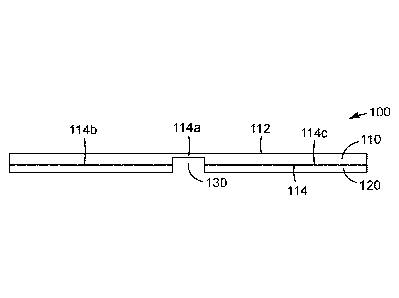
Fig. 1A shows a first aspect of the invention, a distribution cabling tape 100
(also
referred to herein as a road surface conduit) that includes a durable,
resilient polymeric base
sheet 110 having a first major surface 114 and a second major surface 112. The
first major
.. surface 114 includes a continuous lengthwise channel 130 formed in a first
portion 114a thereof.
The channel 130 is configured to receive at least a portion of a distribution
cable, such as cable
150 shown in Fig. 1C. While a single channel 130 is shown in Fig. 1A, in other
aspects of the
invention, a distribution cabling tape can include multiple channels (see
e.g., Fig. 1E). In
addition, tape 100 includes an adhesive layer 120 disposed on a second portion
114b and a third
portion 114c of the first major surface 114. In one aspect, the adhesive layer
120 comprises a
composition that is capable of adhering to a concrete or asphalt (or asphalt-
concrete hybrid)
surface, such as a road, curb or walkway surface, such as road 105 shown in
Fig. 1C. In some
aspects, the channel 130 is adhesive free. In other aspects, the channel 130
may include some
amount of adhesive in it to help hold the distribution cable in place during
deployment. In
-4-
CA 03031349 2019-01-18
WO 2018/017475
PCT/US2017/042375
another aspect, the adhesive layer 120 can comprise a composition that is
capable of adhering to
an alternative road surface, such as a cobblestone or brick surface.
It is noted that while structure 100 is referred to herein as a "tape," this
term is not meant
to exclude other types of adhesive-coated structures, such as adhesive-coated
road patches,
panels or markers that can provide a protective conduit or other type of
pathway for cables. In
addition, the distribution cabling tape can also provide a protective pathway
for electrical or
power lines that are to be distributed through a neighborhood, or across a
road, curb, street,
parking lot or sidewalk, or for cabling repairs and/or splices. Moreover, the
adhesive can be
selected to provide either a temporary or more permanent type of bond to the
road, curb, or
walkway, thus providing a distribution cabling solution for short term events
(such as concerts,
sporting events, festivals, and the like), or for more longer duration
deployment situations (such
as subdivisions in development). In addition, while the tape embodiments
described herein are
often used in road, curb, sidewalk, or street applications, in alternative
embodiments, the
distribution cabling tape can be used to distribute cabling along other
surfaces, such as along or
up the side of a building, tower, bridge, or other structures. Further, while
cable 150 is described
herein as a distribution cable, tape 100 can be used to route and/or protect
many different types
of cables, including communication cables, power cables (such as low voltage
power cables),
sensor wires, co-axial cables, signal cables, and other conventional cables,
or other types of
equipment, such as sensors, RFID tags, embedded antennas, antenna feeds, and
location markers.
Fig. 1B shows another aspect of the invention, a distribution cabling tape
100' that
includes a resilient polymeric base sheet 110 having a first major surface 114
and a second major
surface 112 that comprises a patterned surface 113 having a plurality of
raised structures. The
first major surface 114 includes a continuous lengthwise channel 130 formed in
a first portion
114a thereof. The channel 130 is configured to receive at least a portion of a
distribution cable,
such as cable 150 shown in Fig. 1C. While Fig. 1B shows that channel 130 is co-
located with a
raised pattern structure, in other aspects, channel 130 may not be co-located
with a raised pattern
surface structure. In this aspect, the channel 130 is co-located with a
lengthwise raised structure
113a so that the overall height of the tape 100' is not altered by the
inclusion of the channel 130
and/or cable 150. In addition, tape 100' includes an adhesive layer 120
disposed on a second
portion 114b and a third portion 114c of the first major surface 114. The
adhesive layer
comprises a composition that is capable of adhering to a concrete or asphalt
surface, such as a
road, curb, or walkway surface, such as road 105 shown in Fig. 1C. Fig. 1D is
a perspective
view of adhesive-backed structure or tape 100'.
-5-
CA 03031349 2019-01-18
WO 2018/017475
PCT/US2017/042375
Fig. 1C shows another aspect of the invention, a distribution cabling tape
100" that
includes a resilient polymeric base sheet 110 having a first major surface 114
and a second major
surface 112 that comprises a patterned surface 113 having a plurality of
raised structures. The
first major surface 114 includes a continuous lengthwise channel 130 formed in
a first portion
114a thereof. The channel 130 is configured to receive at least a portion of a
distribution cable
150. In this aspect, the distribution cable 150 includes one or more
electrical lines or optical
fibers 155. In some aspects, cable 150 can include one or more strength
members 152a, 152b,
such as is present in commercially available cable, such as 3M' Clear Fiber
Drop Cable
(available from 3M Company, St. Paul MN), ROC' Drop Dielectric Cable
(available from
Corning Inc., Hickory NC). Other suitable cables include CampusLink"
Indoor/Outdoor cable
(available from Prysmian Group, Lexington, SC). In this aspect, the channel
130 may be co-
located with a lengthwise raised structure so that the overall height of the
tape 100' is not altered.
Alternatively, in some aspects, the distribution cable 150 can comprise a
conventional ribbon
fiber having multiple fibers or a series of parallel optical fibers disposed
on a filament tape to
allow straightforward access to separate individual fibers by peeling off a
portion of the filament
tape. As such, the distribution cable 150 can have a circular, oval, or
rectangular cross section
profile. In other alternative embodiments, channel 130 can be configured to
accommodate more
than one distribution cable, such as cable 150.
In addition, tape 100" includes an adhesive layer 120 disposed on a second
portion 114b
and a third portion 114c of the first major surface 114. The adhesive layer
comprises a
composition that is capable of adhering to an asphalt or concrete surface,
such as a road, curb, or
walkway surface 105.
Fig. lE shows yet another aspect of the invention, a distribution cabling tape
100" that
includes a resilient polymeric base sheet 110 having a first major surface 114
and a second major
surface 112 that comprises a patterned surface 113 having a plurality of
raised structures. The
first major surface 114 includes multiple continuous lengthwise channels,
130a, 130b, and 130c
formed in a first portion thereof Of course, depending on the application, a
fewer number (e.g.,
2) or a greater number (e.g., 4, 5) of channels can be formed in the first
major surface of the base
sheet 110. The channels 130a-130c are each configured to receive at least a
portion of a
distribution cable, such as cable 150 shown in Fig. 1C. While Fig. lE shows
that channels 130a-
130c are each co-located with a raised pattern structure, in other aspects,
channels 130a-130c
may not be co-located with a raised pattern surface structure in other
embodiments. In this
aspect, the channels 130a-130c are each co-located with a lengthwise raised
structure so that the
overall height of the tape 110" is not altered by the inclusion of the
channels 130a-130c and/or
-6-
CA 03031349 2019-01-18
WO 2018/017475
PCT/US2017/042375
the inserted cables. In addition, tape 100"' includes an adhesive layer 120
disposed on
remaining portions of the first major surface 114. The adhesive layer
comprises a composition
that is capable of adhering to a concrete or asphalt surface, such as a road,
curb, or walkway
surface, such as road 105 shown in Fig. 1C.
Fig. 1F shows another aspect of the invention, a distribution cabling tape
100" that
includes a resilient polymeric base sheet 110 having a first major surface 114
and a second major
surface 112. In this embodiment, the first major surface 114 is substantially
continuous across
the side to side width of the tape 100'. In this embodiment, a first portion
114a of the surface
114 is not covered with an adhesive layer. In an alternative embodiment, first
portion 114a can
to be coated with an adhesive layer.
The portion 114a is configured to accommodate at least a portion of at least
one
distribution cable, such as cable 150, similar to those described above. In
addition, tape 100"
includes an adhesive layer 120 disposed on a second portion 114b and a third
portion 114c of the
first major surface 114. The adhesive layer comprises a composition that is
capable of adhering
to a concrete or asphalt surface, such as a road, curb, or walkway surface,
such as road 105
shown in Fig. 1C. Further, in this embodiment, tape 100' includes wing
portions 116a and 116b
that taper to a narrower base sheet thickness at the tape side ends. In this
manner, the outer
edges of the tape can be less susceptible to damage and can accommodate a more
contoured road
or other mounting surface.
In an alternative embodiment, resilient polymeric base sheet 110 can be formed
from a
single material, or, alternatively, different materials. For example, as shown
in Fig. 1F, a first
portion 110a of polymeric base sheet 110 can be formed from a first material,
such as a
toughened or semi-rigid polymer material and second and third portions 110b,
110c of polymeric
base sheet 110 can be formed from a different material, such as a more
flexible elastomeric
(lower modulus) material. Such a composite base sheet 110 can be formed by
coextruding the
two different polymers, as would be apparent to one of skill in the art given
the present
description.
Fig. 1G shows another aspect of the invention, a distribution cabling tape
100" that
includes a resilient polymeric base sheet 110 having a first major surface 114
and a second major
surface 112 that comprises a patterned surface 113 having a plurality of
raised structures. The
resilient polymeric base sheet 110 can be formed from a single material or a
coextrusion of
multiple materials, such as described above.
In this embodiment of Fig. 1F, the first major surface 114 is substantially
continuous
across the side to side width of the tape 100". A first portion 114a of the
surface 114 is not
-7-
CA 03031349 2019-01-18
WO 2018/017475
PCT/US2017/042375
covered with an adhesive layer. First portion 114a can accommodate at least a
portion of a
distribution cable, such as cable 150, similar to those described above. In
alternative
embodiments, raised structures can be included (or not included) over the tape
region covering
cable 150. In addition, tape 100' includes an adhesive layer 120 disposed on a
second portion
114b and a third portion 114c of the first major surface 114. The adhesive
layer comprises a
composition that is capable of adhering to a concrete or asphalt surface, such
as a road, curb, or
walkway surface, such as road 105 shown in Fig. 1C. Further, in this
embodiment, tape 100'
includes wing portions 116a and 116b that taper to a narrower base sheet
thickness at the tape
side ends. In this manner, the outer edges of the tape can be less susceptible
to damage and can
to .. accommodate a more contoured road or other mounting surface.
Fig. 1H shows another aspect of the invention, a distribution cabling tape
100" that
includes a resilient polymeric base sheet 110 having a first major surface 114
and a second major
surface 112 that comprises a patterned surface 113 having a plurality of
raised structures. In
alternative aspects, resilient polymeric base sheet 110 can be formed from a
single material, or,
alternatively, different materials, such as described above. In this
embodiment, the first major
surface 114 is substantially continuous across the side to side width of the
tape 100". A first
portion 114a of the surface 114 is not covered with an adhesive layer. First
portion 114a can
accommodate at least a portion of at least one distribution cable, such as
cable 150, similar to
those described above. In this embodiment, raised structures are present over
the tape region
.. covering cable 150. In addition, tape 100" includes an adhesive layer 120
disposed on a second
portion 114b and a third portion 114c of the first major surface 114. The
adhesive layer
comprises a composition that is capable of adhering to a concrete or asphalt
surface, such as a
road, curb, or walkway surface, such as road 105 shown in Fig. 1C.
Fig. 11 shows another aspect of the invention, a distribution cabling tape
100" that
includes a resilient polymeric base sheet 110 having a first major surface 114
and a second major
surface 112 that comprises a patterned surface 113 having a plurality of
raised structures.
However, in this aspect, one or more of the raised structures, such as
structure 113a, are milled
down to provide an overall flatter upper surface. In alternative aspects,
resilient polymeric base
sheet 110 can be formed from a single material, or, alternatively, different
materials, such as
described above. In this embodiment, the first major surface 114 is
substantially continuous
across the side to side width of the tape 100" and is covered with an adhesive
layer 120 that is
capable of adhering to a concrete or asphalt surface, such as a road, curb, or
walkway surface,
such as road 105 shown in Fig. 1C. A first portion 114a of the surface 114 may
be covered with
-8-
an adhesive layer 120. First portion 114a can accommodate at least a portion
of at least one
distribution cable, such as cable 150a, similar to those described above.
In more detail, applied to the bottom surface 114 of the base sheet 110 is an
adhesive
120, such as a pressure sensitive adhesive (PSA). In one aspect, the PSA 120
is designed to
adhere to a common road, curb, or walkway surface, such as concrete and
asphalt surfaces, and
to withstand the wide temperature variations, weather and chemicals present.
For example,
acceptable PSA formulations are described in US 5,906,889 and US 5,453,320. In
another
aspect, the adhesive can comprise a heat activated adhesive. In addition,
other types of
adhesives can be used, depending on the duration of the intended deployment of
the distribution
cabling tape.
The adhesive layer 120 is applied to a resilient base sheet 110. Sheet 110 has
a top
surface 112 and a bottom surface 114. One or more portions of the bottom
surface 114, such as
portions 114b and 114c are in contact with the adhesive layer 120. In one
aspect, the base sheet
110 can be made from non-crosslinked elastomer precursors. The base sheet 110
is preferably
made of a durable construction to withstand continual impacts made by vehicles
and/or
pedestrians. Acceptable base sheet compositions have been described in, for
example,
US 4,117,192, US 4,490,432, US 4,282,281, US 2014/0011911, and US 5,853,846.
In one
aspect, the base sheet can comprise a thermoplastic material.
In some other aspects, the base sheet can comprise a more conformable
material, such
that when the distribution cable is inserted in a channel, the channel can
conform about an outer
shape or profile of the distribution cable, for example, after the
distribution cable is inserted in
the channel, or after the distribution cable is installed on the road surface.
In a further alternative
aspect, the base sheet can comprise a fabric material, or a scrim, such as is
described in
US 7,169,831 and US 5,981,033, which can make the distribution cabling tape
removable in a
straightforward manner, which can be useful in temporary deployment
applications, such as for
short duration events or in repair applications. In addition, as mentioned
above, the base sheet
can also comprise a composite of different materials, such as different
polymeric materials. For
example, a composite base sheet can be formed by coextruding two different
polymers, such as a
toughened or semi-rigid polymer material and a more flexible elastomeric
(lower modulus)
material.
The second or top layer 112 of the base sheet 110, may be a flat surface (such
as shown
in Fig. 1A) or it may have a raised pattern surface 113 (such as is shown in
Fig. 1B). The base
sheet 110 can be any color so that the tape can stand out (such as including
white or yellow
coloring) or it can blend into the surface upon which it is mounted (such as
including gray or
-9-
Date Recue/Date Received 2023-01-20
black coloring) or it can be covered with conventional road surfacing or
resurfacing materials.
Retroreflective elements, glass and/or ceramic beads, can be embedded directly
on the second
surface 112 as is described in US 4,388,359. Alternatively, the second surface
112 can be coated
with either a thermoplastic or thermosetting layer. For flat markings, an
example of a
thermoplastic material is described in US 4,117,192, and for thermosetting an
example material
is described in US 5,077,117. For base sheets 110 having a plurality of raised
protuberances,
example materials are described in US 4,988,541, US 5,683,746, US 5,593,246,
US 6,479,132,
US 5,928,761, US 5,227,221, and US 5,763,000. Additionally, other patterns and
designs of
raised protuberances are described in US 4,388,359, US 4,988,541, US
5,683,746, and US
4,681,401. For applications where roads may be subject to snow and ice
accumulation,
exemplary base sheets designed to resist the action of snowplow blades are
described in US
4,129,673, US 4,685,824, and US 6,431,788. Exemplary commercially available
pavement
marking tapes include those sold under the Stamarlem brand, including 380 IES
and 380 AW
models, available from 3M Company, St. Paul Minnesota.
Acceptable methods of forming a tape structure using the exemplary base sheets
and
adhesives described herein can include hot embossing, double sided embossing,
patterned nip
rolls, doctor blading (for adhesives), and pattern coating techniques. For
example, patterned
embossing rolls can be brought into contact with opposing sides of a web of
the base sheet
material to generate the desired patterns on each side of the base sheet
(e.g., diamonds on the air
.. side (e.g., surface 112) and continuous channel on the road side (e.g.,
surface 114)). Doctor
blades or pattern coating can be used to apply adhesives in non-channel areas.
Fig. 2A shows another aspect of the invention, a distribution cabling tape 200
that
includes a resilient polymeric base sheet 210 having a first major surface 214
and a second major
surface 212 that comprises a patterned surface 213 having a plurality of
raised structures. In this
aspect, a distribution cable 250 is embedded in the tape 200. For example, in
alternate
configurations, the distribution cable 250 can be embedded between the first
major surface 214
and the adhesive layer 220, the distribution cable 250 can be embedded within
the adhesive layer
220, or the distribution cable 250 can be embedded between the adhesive layer
220 and the road
surface 205. Preferably, in this aspect, the distribution cable 250 can be a
low profile fiber cable,
such as a fiber ribbon cable, having a plurality of optical fibers (in this
example, fibers 250a-
-10-
Date Recue/Date Received 2023-01-20
CA 03031349 2019-01-18
WO 2018/017475
PCT/US2017/042375
250g). Although not shown, distribution cable 250 can include additional
strength members
(e.g., Kevlar yarn or glass fiber rods (FRP)) to help reduce axial strain on
the fiber as the road
expands and/contracts with daytime heating and seasonal temperature
variations. The adhesive
layer 220 and the base sheet 210 can be constructed as described above.
Fig. 2B shows another aspect of the invention, a distribution cabling tape
200' that
includes a resilient polymeric base sheet 210 having a first major surface 214
and a second major
surface 212 that comprises a patterned surface 213 having a plurality of
raised structures. In
addition, tape 200' includes an adhesive layer 220 disposed on a first portion
214a and a second
portion 214b of the first major surface 214. The adhesive layer comprises a
composition that is
capable of adhering to an asphalt or concrete surface, such as road, curb, or
walkway surface
205. In this aspect, a gap 220a is formed between adhesive sections that is
adhesive free and is
configured to receive a distribution cable 250, or at least a portion thereof.
Preferably, in this
aspect, the distribution cable 250 can be a low profile fiber cable, such as a
fiber ribbon cable,
having a plurality of optical fibers. The adhesive layer 220 and the base
sheet 210 can be
constructed as described above.
Fig. 2C shows yet another aspect of the invention, a distribution cabling tape
200" that
includes a resilient polymeric base sheet 210 having a first major surface 214
and a second major
surface 212 that comprises a patterned surface 213 having a plurality of
raised structures. In
addition, tape 200" includes an adhesive layer 220 disposed on the first major
surface 214. The
adhesive layer comprises a composition that is capable of adhering to a road,
curb, or walkway
surface 205. In this aspect, a relatively shallow surface channel 207 is
formed in the road, curb,
or walkway surface 205. A distribution cable 250 can be received in channel
207 and the tape
200" can be disposed directly above the surface channel 207. The channel 207
can be formed
with a conventional road surface grinding tool, such as are available from
Smith Manufacturing
(Pompano Beach, FL). In one example, the surface channel 207 can have a width
and depth of
about 1/4" ¨ 1" to receive a conventional fiber drop cable, such as the ROC Tm
Drop Dielectric
Cable (available from Corning Inc., Hickory NC). In this aspect, the channel
or pathway can
have a width and depth sufficient to allow the distribution cable to "float"
within the pathway as
the road expands and contracts with daytime heating and seasonal temperature
changes.
Optionally, in addition to the distribution cable 250, in some aspects of the
invention, a sealant
or adhesive can be applied to the surface channel 207. For example, an added
sealant can help
prevent water build-up within the surface channel. An exemplary sealant can
comprise, for
example, SafetrackTm MTI sealant available from StirlingLloyd Polychem Ltd
(UK). The
adhesive layer 220 and the base sheet 210 can be constructed as described
above.
-11-
CA 03031349 2019-01-18
WO 2018/017475
PCT/US2017/042375
Further, different sections of surface channel 207 can be configured with a
different
shape, such as a wider channel or trench, so as to accommodate different types
of network
devices, such as splices or other equipment.
It is noted that if a distribution cable of a certain size were placed under a
road surface
tape that did not include a channel therein or if there were no channel or
trench formed in the
road surface, the tape would likely bulge at the cable location. This
protrusion would
concentrate the tire load onto the distribution cable and would likely cause
premature wear of the
road surface tape in this region.
Fig. 2D shows yet another aspect of the invention, a distribution cabling tape
200" that
includes a resilient polymeric base sheet 210 having a first major surface 214
and a second major
surface 212 that comprises a patterned surface 213 having a plurality of
raised structures. In
addition, the first major surface 214 includes a continuous lengthwise channel
230 formed in a
first portion thereof. The channel 230 is configured to receive at least a
portion of a distribution
cable 250. In this aspect, the distribution cable 250 includes one or more
electrical lines or
optical fibers and can comprise a cable such as those described above. An
adhesive layer 220
disposed on the first major surface 214 on one or both sides of channel 230.
The adhesive layer
comprises a composition that is capable of adhering to a road or walkway
surface 205. In this
aspect, a relatively shallow surface channel 207 is formed in the road or
walkway surface 205.
The tape 200' can be disposed directly above the surface channel 207 such that
distribution
cable 250 can be received in the spaced defined by channel 230 and channel
207. The channel
207 can be formed with a conventional road surface grinding tool, such as
those described
above. The adhesive layer 220 and the base sheet 210 can be constructed as
described above.
Alternatively, as would be apparent to one of skill in the art given the
present description, tape
200' can be further modified to include multiple channels (see e.g., Fig. 1E)
and road surface
207 can also include multiple channels, as appropriate.
In a further alternative, a distribution cabling tape that does not include a
channel formed
in the base sheet and that is adhesive free over a central portion of the
first major surface (see
e.g., tape 200') can be placed over a road surface channel 207 to provide a
protective covering
for a distribution cable 250 installed in channel 207.
Fig. 3A shows yet another aspect of the invention, a distribution cabling tape
300 that
includes a resilient polymeric base sheet 310 having a first major surface 314
and a second major
surface 312 that comprises a patterned surface 313 having a plurality of
raised structures. In this
aspect, a distribution cable 350 is embedded in the tape 300, such as is
described above with
respect to Fig. 2A. For example, in alternate configurations, the distribution
cable 350 can be
-12-
CA 03031349 2019-01-18
WO 2018/017475
PCT/US2017/042375
embedded between the first major surface 314 and the adhesive layer 320, the
distribution cable
350 can be embedded within the adhesive layer 320, or the distribution cable
350 can be
embedded between the adhesive layer 320 and the road surface. The adhesive
layer 320 and the
base sheet 310 can be constructed as described above. Further, in this aspect
of the invention,
the road surface 305 includes a wide trench 308 that is configured in depth
and width to receive
the entire width of the tape 300, such that the top surface 312 is
substantially at road surface
level. In this manner, especially for environments where ice and snow
accumulation are
common, the tape 300, and thus the distribution cable 350, can be protected
from snow plows
and other road surface servicing equipment.
In a further alternative aspect, a distribution cabling tape 300 can be
constructed as
shown in any of the above tape constructions. For example, as is shown in Fig.
3B, a
distribution cabling tape 300' includes a resilient polymeric base sheet 310
having a first major
surface 314 and a second major surface 312 that comprises a patterned surface
313 having a
plurality of raised structures. In addition, tape 300' includes an adhesive
layer 320 disposed on
the first major surface 314. The adhesive layer comprises a composition that
is capable of
adhering to a concrete or asphalt surface, such as a road, curb, or walkway
surface 305. In this
aspect, the road surface 305 includes a wide trench 308 that is configured in
depth and width to
receive the entire width of the tape 300', such that the top surface 312 is
substantially at road
surface level. In addition, a second, narrower shallow channel 307 is formed
in the bottom
surface of trench 308 such that a distribution cable 350 can be received in
channel 307 and the
tape 300' can be disposed directly above the channel 307. The trench 308 and
channel 307 can
be formed with conventional road surface grinding tools. In a further
alternative aspect,
additional channels or trenches can be utilized to accommodate splices or
extra fiber(s) to
accommodate strain and future repairs.
In a further aspect of the invention, a distribution cabling tape can be
formed having a
curved channel or curved break-out channels to allow for cables to exit the
distribution cabling
tape in any direction. For example, Fig. 5A shows a distribution cabling tape
500. In this
configuration, tape 500 is configured as a patch to accommodate a right angle
turn. In this
aspect, channel 530, which can be foitned in a first major surface of the
backing sheet (such as is
described previously) can include a curved portion 531, which allows a
distribution cable to
enter a first side 504a and exit an adjacent side 504b. Alternatively, the
channel 530 can be
curved at a different angle than a right angle, depending on the cable routing
application.
Optionally, the road surface can also include a corresponding curved channel.
-13-
CA 03031349 2019-01-18
WO 2018/017475
PCT/US2017/042375
In a further alternative, a distribution cabling tape can include several
break-out channels
that can allow one or more communication or power lines within the
distribution cable to branch
out from the main cable. For example, Figs. 5B and 5C shows a distribution
cabling tape 500'.
In Fig. 5B, tape 500' is configured as a patch to accommodate one or more
branch outs (e.g.,
substantially right angle turns). In this aspect, the channel 530, which can
be formed in a first
major surface of the backing sheet (such as is described previously), can
include a main channel
530a and multiple branches 530b and 530c. In this configuration, a
distribution cable entering a
first side 504a can have at least one communication line branch out from the
main cable and exit
an adjacent side 504b or 504c, with the remainder of the communication lines
continuing
towards side 504d. In Fig. 5C, tape 500' is configured as a tape having a
length L much greater
than its width W. In Fig. 5C, tape 500' includes repeating branching sections
(three such
sections are shown in the figure), with branches 530b-530g providing branching
locations for
communication lines within the main distribution cable.
In a further aspect of the invention, multiple distribution cabling tapes can
be used to
route a distribution cable over multiple surfaces. As shown in Fig. 5D, a
first distribution
cabling tape 500a, a distribution cabling patch 500b, and a second
distribution cabling tape 500c
can be used to route a distribution cable (not shown) from a road surface 505
across and along a
curb 506. For example, a distribution cable can be routed along channel 530a
to a patch 500b
mounted at curb 506. One or more communication lines can be routed along
channel 530b to
curved channel 530c and then along channel 530d of distribution cabling tape
500c.
As would be understood by one of ordinary skill in the art given the present
description, a
cable routing deployment (in a neighborhood or other venue) can use any number
of
combinations of the distribution cabling tapes and patches described herein.
Further, the
continuous channels formed in the tapes and road surfaces need not be formed
as straight lines.
Additionally, the distribution cabling tape or road surface may include a loop
shaped channel or
trench configured to accommodate slack storage for future repairs.
The distribution cabling tape embodiments described herein can be employed as
part of a
fiber access network and provide a cost effective and rapidly deployable
alternative to traditional
fiber-to-the-home, building, or event site methods. For example, one such
application
employing the distribution cabling tape embodiments described herein for a
communications
application is shown in Fig. 4. Network 401 is provided to a neighborhood
having a plurality of
homes. In this aspect of the invention, the telecommunications cabling can be
provided on the
road surface using one or more of the road surface conduit structures
described above. In this
aspect, traditional telecommunications cabling, such as fiber drop cables, can
be used in the road
-14-
surface conduit. Shallow grooves, such as groove 207 described above in Fig.
2C, are ground
into the road surface 405 in the pathways shown in Fig. 4. Distribution cable
450 bring fibers
from the central office to each telininal 460 using road surface conduit 400a.
Inside the
terminal, drop cables 451 are connected to the appropriate distribution fiber
and run to each
home via one or more road surface conduits 400b ¨ 400d. In more detail, drop
cables 451 that
need to run across the street can again be laid in a road surface groove and
protected/encased by
any of road surface conduits 400b ¨ 400d.
In one aspect, the distribution cable 450 can have be a fiber count suitable
for a
centralized split FTTh architecture (e.g., 144 fiber) or a fiber count
suitable for a distributed split
It) FTTh architecture (e.g., 12 fiber). Example fiber cabling includes
MiniXtendTm 144ZM4-
T4F22A20 (available from Coming Inc.) that is broken out to single fiber drops
in the terminal.
A suitable smaller fiber count cable includes Mini LT Flat Drop AT-5BE8T7X-12
(available
from OFS) that is power split to the single fiber drops in the terminal. In
either case, a
conventional drop cable 451 can include a Mini LT Flat Drop AT-5BE8T7X-1 or 2
(available
from OFS). The adhesive backed structure or tape 400a-400d can have a durable
construction,
similar to the backing/adhesive constructions described above. As such, the
adhesive backed
structure or tape 400a-400d provide cable protection for an extended period of
time, even if used
on a temporary basis, until a traditional underground conduit is installed. In
addition, the
distribution cabling tape can be used for repairing faults. For example, if a
fault was discovered,
the original distribution cabling tape can be removed at the fault location, a
repair splice to the
line or lines can be made at that location, and a new tape or tape section can
be applied to cover
the splice or repair.
In addition, it is expected that a road surface may undergo significant shifts
and cracks
which could severely stress the distribution cable. As such, in some aspects,
an excess
distribution cable length can be provided during installation. In one example,
the cable would
purposely be applied with a, e.g., sinusoid pattern so that it has 1-2% excess
length. When the
road surface shifts, this region of cable would be strained into a sine wave
of reduced amplitude,
or become substantially straight.
The distribution cabling tape thus allows a service provider the opportunity
to quickly
connect a sufficient number of customers in a neighborhood or building before
making a large
infrastructure investment. In this manner, each of the houses in this area of
the neighborhood
can be rapidly accessed without having to utilize directional drilling or
other massive road
destruction and repair procedures.
-15-
Date Recue/Date Received 2023-01-20
CA 03031349 2019-01-18
WO 2018/017475
PCT/US2017/042375
Other applications for the tape constructions described herein can also be
implemented.
For example, the adhesive backed structure or tape can be configured to
further ruggedize drop
cable for direct buried applications. The tape can continue off the road and
can be wrapped
around the drop cable making a robust transition from the road surface to
below grade bury of
the cable and continuing all the way to the house if deemed necessary. In
addition, the road
surface conduit can be deployed on a curb adjacent to the street thereby
eliminating network
disruption when the street is resurfaced. The road surface conduit can be
deployed with pre-
fabricated distribution cable assemblies (e.g., FlexNap, available from
Corning, Inc.) where the
access branch point is accommodated in the road surface. An alternative
deployment technique
can include utilizing a RetractaNetT" cable (available from Prysmian Group,
Lexington, SC) and
one or more window cuts to access one or more of the individual communication
lines therein.
In addition, the distribution cabling tape embodiments described herein can be
used to distribute
cabling along other surfaces, such as along or up the side of a building,
tower, bridge, or other
structures.
While a preferred application of the distribution cabling tape is for
telecommunication
applications, as mentioned previously, other applications can include pathways
for power,
sensors or sensing or electronics for smart road applications.
Experiment
In a first experiment, 28 samples of the various configurations described
above were
prepared in short sections and tested on a vehicle wear simulator (VWS). The
VWS can include
a drum covered with an appropriate surface material to simulate, e.g., highway
pavement. A car
tire loaded at 1000 pounds is pressed against the drum. The VWS can be run at
about 120 RPM,
corresponding to approximately 50 mph, and at a constant temperature (e.g., 35
C) for about 10
hours to simulate vehicle tire hits.
Samples were applied to the road surfaces with fiber optic cables in the test
apparatus.
Simulated tire hits over the samples were conducted and fiber continuity was
observed at
increasing intervals of simulated tire hits. The results from this testing
showed no fiber breaks
for all of the configurations tested to 1 million tire hits.
In another experiment, a freeze-thaw test was conducted on another sample that
was
configured in a manner consistent with that shown in Fig. 2C, described above.
In this
experiment, a concrete block was grooved with a 1/4" wide by 1/4" deep groove.
A section of
Corning ROC cable, 001EB1-14701DF9, was laid in the groove and a road surface
tape was
applied over the cable to encase the fiber optic cable similar to that shown
in Fig. 2C. The
sample was placed in a metal tub and covered with water. The tub was placed in
an
-16-
CA 03031349 2019-01-18
WO 2018/017475
PCT/US2017/042375
environmental chamber from -30 C freezing conditions to +60 C thawing
conditions. The
sample was completely frozen and completely thawed several times with no
disruption of the
road tape, fiber optical cable or concrete block.
Various modifications, equivalent processes, as well as numerous structures to
which the
present invention may be applicable will be readily apparent to those of skill
in the art to which
the present invention is directed upon review of the present specification.
-17-