Language selection

Search

Patent 3032134 Summary

Third-party information liability

Some of the information on this Web page has been provided by external sources. The Government of Canada is not responsible for the accuracy, reliability or currency of the information supplied by external sources. Users wishing to rely upon this information should consult directly with the source of the information. Content provided by external sources is not subject to official languages, privacy and accessibility requirements.

Claims and Abstract availability

Any discrepancies in the text and image of the Claims and Abstract are due to differing posting times. Text of the Claims and Abstract are posted:

  • At the time the application is open to public inspection;
  • At the time of issue of the patent (grant).
(12) Patent Application: (11) CA 3032134
(54) English Title: OUTDOOR WEATHER RESISTANT OUTLET COVER
(54) French Title: COUVERCLE DE SORTIE RESISTANT AUX INTEMPERIES A L'EXTERIEUR
Status: Examination
Bibliographic Data
(51) International Patent Classification (IPC):
  • H02G 03/08 (2006.01)
  • H01R 13/46 (2006.01)
  • H01R 13/52 (2006.01)
  • H02G 03/14 (2006.01)
  • H05K 05/03 (2006.01)
(72) Inventors :
  • MORTUN, SORIN (United States of America)
(73) Owners :
  • HUBBELL INCORPORATED
(71) Applicants :
  • HUBBELL INCORPORATED (United States of America)
(74) Agent: FINLAYSON & SINGLEHURST
(74) Associate agent:
(45) Issued:
(86) PCT Filing Date: 2017-07-28
(87) Open to Public Inspection: 2018-02-01
Examination requested: 2022-06-28
Availability of licence: N/A
Dedicated to the Public: N/A
(25) Language of filing: English

Patent Cooperation Treaty (PCT): Yes
(86) PCT Filing Number: PCT/US2017/044397
(87) International Publication Number: US2017044397
(85) National Entry: 2019-01-25

(30) Application Priority Data:
Application No. Country/Territory Date
62/367,936 (United States of America) 2016-07-28

Abstracts

English Abstract

An in-use outlet cover includes a base configured to be positioned over an electrical receptacle. The base having a recessed portion at least partially defining a chamber configured to receive a plug to connect a load to the outlet. A cover assembly is pivotally connected to the base. An expandable member can positioned in a central opening of the base and moveable between a first position where the expandable member has a first volume and a second position where the expandable member has a second volume greater than the first volume, and wherein movement of the expandable member varies the size of the chamber. The cover assembly can additionally or alternatively include a lower cover pivotally connected to the base and an upper cover pivotally connected to the lower cover.


French Abstract

La présente invention concerne un couvercle de sortie en cours d'utilisation qui comprend une base conçue pour être positionnée sur une prise électrique. La base comporte une partie évidée définissant au moins partiellement une chambre conçue pour recevoir une fiche d'alimentation électrique permettant de connecter une charge à la sortie. Un ensemble couvercle est relié de manière pivotante à la base. Un élément expansible peut être positionné dans une ouverture centrale de la base et être mobile entre une première position dans laquelle l'élément extensible présente un premier volume et une seconde position dans laquelle l'élément extensible présente un second volume supérieur au premier volume, et le mouvement de l'élément expansible fait varier la taille de la chambre. L'ensemble couvercle peut également ou alternativement comprendre un couvercle inférieur relié de manière pivotante à la base et un couvercle supérieur relié de manière pivotante au couvercle inférieur.

Claims

Note: Claims are shown in the official language in which they were submitted.


What is claimed:
1. An in-use outlet cover comprising:
a base configured to be positioned over an electrical receptacle, the base
having a recessed portion at least partially defining a chamber configured to
receive a plug to connect a load to the outlet;
a cover assembly pivotally connected to the base and having a central
opening; and
an expandable member positioned in the central opening and moveable
between a first position where the expandable member has a first volume and
a second position where the expandable member has a second volume greater
than the first volume, and wherein movement of the expandable member
varies the size of the chamber.
2. The in-use outlet cover of claim 1, wherein the expandable member includes
a
flexible side wall.
3. The in-use outlet cover of claim 2, wherein the side wall is corrugated.
4. The in-use outlet cover of claim 1, wherein the expandable member includes
a
flange having a set of openings and wherein the cover assembly includes a set
of bosses configured to engage the openings.
5. The in-use cover of claim 1, wherein the expandable member is at least
partially transparent.
6. The in-use outlet cover of claim 1, wherein the cover assembly includes a
lower
cover pivotally connected to the base and an upper cover pivotally connected
to the lower cover.
~ 8 ~

7. The in-use outlet cover of claim 1, wherein the cover assembly is
configured to
pivot about a first axis along a long side of the cover assembly and about a
second axis along a short side of the cover assembly.
8. An in-use outlet cover comprising:
a base configured to be positioned over an electrical receptacle, the base
having a substantially rectangular configuration with first and second short
sides and first and second long sides;
a lower cover having a substantially rectangular configuration with first
and second short sides and first and second long sides, the first short side
of
the lower cover pivotally connected to the first short side of the base; and
an upper cover having a substantially rectangular configuration with first
and second short sides and first and second long sides, the first long side of
the upper cover pivotally connected to the first long side of the lower cover.
9. The in-use outlet cover of claim 8, wherein a first cord opening is defined
by a
first aperture in the second long side of the upper cover and a second
aperture
in the second long side of the lower cover and a second cord opening is
defined by a third aperture in the second short side of the lower cover and a
fourth aperture in the second short side of the base.
10. The in-use outlet cover of claim 9, wherein a first seal is provided to
seal the
first cord opening and a second seal is provided to seal the second cord
opening.
11. The in-use outlet cover of claim 10, wherein the first seal is positioned
in a
channel in the lower cover and the second seal is positioned in a channel in
the base.
~ 9 ~

12. The in-use outlet cover of claim 8, wherein the base includes a connection
member configured to connect the base to the receptacle.
13. The in-use outlet cover of claim 12, wherein the connection member
includes a
snap-fit connection feature.
14. The in-use outlet cover of claim 8, wherein the upper cover includes a
central
opening and an expandable member positioned in the central opening and
moveable between a first positioned where the expandable member has a first
volume and a second positioned where the expandable member has a second
volume greater than the first volume.
15. An in-use outlet cover comprising:
a base configured to be positioned over an electrical receptacle, the base
having a substantially rectangular configuration with first and second short
sides and first and second long sides;
a lower cover having a substantially rectangular configuration with first
and second short sides and first and second long sides, the first short side
of
the lower cover pivotally connected to the first short side of the base;
an upper cover having a substantially rectangular configuration with first
and second short sides and first and second long sides, the first long side of
the upper cover pivotally connected to the first long side of the lower cover;
and
an expandable member connected to the upper cover and having an outer
wall and a collapsible side wall, the expandable member moveable between a
first position where the outer wall is positioned a first distance from the
upper
cover and a second position a second distance from the upper cover, wherein
the second distance is greater than the first distance.
16. The in-use outlet cover of claim 15, wherein a first cord opening is
defined by a
first aperture in the second long side of the upper cover and a second
aperture
~ 10 ~

in the second long side of the lower cover and a second cord opening is
defined by a third aperture in the second short side of the lower cover and a
fourth aperture in the second short side of the base.
17. The in-use outlet cover of claim 15, wherein the base is snap-fit to the
receptacle and the base includes a lower wall having a set of receptacle
openings.
18. The in-use outlet cover of claim 15, further comprising a first latch
configured
to secure the lower cover to the base and a second latch configured to secure
the upper cover to the lower cover.
19. The in-use outlet cover of claim 15, wherein the expandable member
includes
a flange having a set of openings and wherein the upper cover includes a set
of
bosses configured to engage the openings.
20.The in-use outlet cover of claim 15, wherein the expandable member includes
a flexible, corrugated side wall.
~ 11 ~

Description

Note: Descriptions are shown in the official language in which they were submitted.


CA 03032134 2019-01-25
WO 2018/023008
PCT/US2017/044397
PATENT APPLICATION
FOR
OUTDOOR WEATHER RESISTANT OUTLET COVER
FIELD
[0001] Various exemplary embodiments of the invention relate to weather
resistant outlet covers.
BACKGROUND
[0002] Electrical outlets may be exposed to rain, snow, debris, and other
contaminants when mounted in outdoor locations, such as exterior walls. In
such
locations, the electrical outlet can be protected with a cover that can be
closed while a
plug is plugged into the outlet. Such outlet covers are called while-in-use
covers.
Typical while-in-use covers include a base surrounding an outlet and a cover
connected to and extending from the base. A plug can be inserted into the
outlet and
the cover has an interior dimension sufficient to allow the cover to be closed
while
the plug is inserted. A cord can extend through an opening in the cover.
[0003] In-use covers conventionally fall two categories ¨ bubble covers and
flush
mount covers. Bubble covers are generally used where the sockets for the
outlet are
mounted near the outer surface of the wall. The outlet is covered by an in-use
cover
by providing a cover that creates a bubble around the cords plugged into the
outlet.
Flush mount covers are generally used where the sockets for the outlet are
mounted
recessed into the wall with the cover closing against the wall. The outlet is
covered by
an in-use cover by the spacing between the cover and the sockets allowing for
a plug
to be plugged into the socket while the cover is closed.
¨ 1 ¨

CA 03032134 2019-01-25
WO 2018/023008
PCT/US2017/044397
SUMMARY
[0004] According to an exemplary embodiment, an in-use outlet cover includes a
base configured to be positioned over an electrical receptacle. The base
having a
recessed portion at least partially defining a chamber configured to receive a
plug to
connect a load to the outlet. A cover assembly is pivotally connected to the
base and
includes a central opening. An expandable member is positioned in the central
opening and moveable between a first position where the expandable member has
a
first volume and a second position where the expandable member has a second
volume greater than the first volume, and wherein movement of the expandable
member varies the size of the chamber.
[0005] According to another exemplary embodiment, an in-use outlet cover
includes a base configured to be positioned over an electrical receptacle. The
base
hhas a substantially rectangular configuration with first and second short
sides and
first and second long sides. A lower cover includes a substantially
rectangular
configuration with first and second short sides and first and second long
sides. The
first short side of the lower cover is pivotally connected to the first short
side of the
base. An upper cover has a substantially rectangular configuration with first
and
second short sides and first and second long sides. The first long side of the
upper
cover is pivotally connected to the first long side of the lower cover.
[0006]
According to another exemplary embodiment, an in-use outlet cover
includes a base configured to be positioned over an electrical receptacle. The
base has
a substantially rectangular configuration with first and second short sides
and first
and second long sides. A lower cover has a substantially rectangular
configuration
with first and second short sides and first and second long sides. The first
short side
of the lower cover is pivotally connected to the first short side of the base.
An upper
cover has a substantially rectangular configuration with first and second
short sides
and first and second long sides. The first long side of the upper cover is
pivotally
connected to the first long side of the lower cover. An expandable member is
connected to the upper cover and has an outer wall and a collapsible side
wall. The
expandable member is moveable between a first position where the outer wall is
¨ 2 ¨

CA 03032134 2019-01-25
WO 2018/023008
PCT/US2017/044397
positioned a first distance from the upper cover and a second position a
second
distance from the upper cover, wherein the second distance is greater than the
first
distance.
BRIEF DESCRIPTION OF THE DRAWINGS
[0007] The aspects and features of various exemplary embodiments will be more
apparent from the description of those exemplary embodiments taken with
reference
to the accompanying drawings, in which:
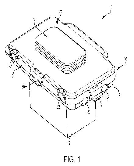
[0008] FIG. 1 is a perspective view of an outlet housing and outlet cover;
[0009] FIG. 2 is a perspective view of FIG. 1 with the outlet cover opened in
a first
direction;
[0010] FIG. 3 is a perspective view of FIG. 1 with the outlet cover opened in
a
second direction;
[0011] FIG. 4 is an exploded view of the outlet cover of FIG. 1;
[0012] FIG. 5 is a sectional view of the outlet cover of FIG. 1;
[0013] FIG. 6 is a top perspective view of the expandable member;
[0014] FIG. 7 is a bottom perspective view of FIG. 6;
[0015] FIG. 8 is a top perspective view of the expandable member;
[0016] FIG. 9 is a bottom perspective view of FIG. 8;
[0017] FIG. 10 is a top perspective view of the lower cover;
[0018] FIG. 11 is a bottom perspective view of FIG. 10;
[0019] FIG. 12 is a top perspective view of the base; and
[0020] FIG. 13 is a bottom perspective view of FIG.12.
DETAILED DESCRIPTION OF EXEMPLARY EMBODIMENTS
[0021] FIGS. 1-3 show an exemplary embodiment of a while-in-use electrical
outlet cover 10 connected to an outlet housing 12. The outlet cover 10
includes a base
14, a cover assembly 16, and an expandable member 18. The cover assembly 16
can
be oriented either horizontally or vertically and pivoted about a first axis
along a
short side of the cover and a second axis along a long side of the cover, as
shown in
¨ 3 ¨

CA 03032134 2019-01-25
WO 2018/023008
PCT/US2017/044397
FIGS. 2 and 3. The cover assembly 16 is a low profile cover so that it does
not extend
from the outlet a sufficient distance to permit a standard plug 20 to be
inserted and
the cover 10 closed.
[0022] To permit the outlet to be used while the cover 10 is closed, the
expandable
member 18 moves between a first, or collapsed, position where the expandable
member is positioned near an outer surface of the cover assembly 16 and a
second, or
extended, position where the expandable member 18 is spaced from the outer
surface
of the cover assembly 16. Accordingly, the expandable member 18 has a first
volume
in the collapsed position and a second, larger volume in the extended
position.
[0023] FIGS. 4 and 5 show an exemplary embodiment of the outlet cover 10 in
more detail. The cover assembly 16 includes a lower cover 22 pivotally
connected to
the base 14 and an upper cover 24 pivotally connected to the lower cover 22.
The
expandable member 18 extends through an opening in the upper cover 24. A first
hinge member 26 pivotally connects the lower cover 22 to the base 14 and a
second
hinge member 28 pivotally connects the upper cover 24 to the lower cover 22.
The
base 14 and cover assembly 16 are shown having a substantially rectangular
configuration with a pair of long sides and a pair of short sides, although
other
configurations can be used depending on the type of outlet and outlet housing.
[0024] One or more openings are provided for cords to extend through the
outlet
cover 10. For example, a first set of openings 30 is at least partially
defined by
apertures in the base 14 and the lower cover 22 along the short side and a
second set
of openings 32 is at least partially defined by apertures in the lower cover
22 and the
upper cover 24 along the long side, as best shown in FIGS. 1-3. A seal or
gasket can
be provided between one or more of the components, as best shown in FIGS. 4
and 5.
A first seal 34 is positioned between the upper cover 24 and lower cover 22 to
provide water resistance to the first set of openings 30 and any cords
extending
therethrough. A second seal 36 is positioned between the lower cover 22 and
the base
14 to provide water resistance to the second set of openings 32 and any cords
extending therethrough. The first and second seals 34, 36 are sized to cover
the
openings 34, 36 when no cord is present and be compressible around a cord to
seal
¨ 4 ¨

CA 03032134 2019-01-25
WO 2018/023008
PCT/US2017/044397
any open space between the cord and the openings 34, 36. A first gasket 38 can
be
provided between the expandable member 18 and the upper cover 24 and a second
gasket 40 can be provided between the base 14 and the outlet housing 12.
[0025] As best shown in FIGS. 6 and 7, the expandable member 18 includes an
outer wall 42, a moveable or collapsible portion 44, a flange 46, and a
recessed
portion 48. The moveable portion 44 can include a flexible, corrugated
material
allowing the outer wall to move between an expanded position and a collapsed
position. The flange 46 includes a series of openings to receive fasteners. In
an
exemplary embodiment, at least a portion of the expandable member 48 can also
be
transparent, allowing a user to see inside of the outlet cover 10. The outer
wall 42,
moveable portion 44, flange 46, and recessed portion 48 can all be
transparent, or
any combination of components can be transparent.
[0026] FIGS. 8 and 9 show an exemplary embodiment of the upper cover 24. The
upper cover 24 has a substantially rectangular configuration with a pair of
long sides
and a pair of short sides. An opening in the upper cover 24 receives the
expandable
member 18. A series of bosses 50 extend from a lower surface of the upper
cover 24.
The bosses 50 can align or extend into the openings in the expandable member
flange 46. The upper cover 24 includes a first hinge portion 52 on one of the
long
sides and a set of apertures 54 and a latch 56 are positioned on the opposite
long
side.
[0027] FIGS. 10 and ii show an exemplary embodiment of the lower cover 22.
The lower cover 22 has a substantially rectangular configuration with a pair
of long
sides and a pair of short sides surrounding a central opening. A channel 58
extends
around the lower cover 22 defined by an outer side wall and an inner side wall
to
receive the first seal 34. The lower cover 22 includes a first hinge portion
60 on one
of the long sides and a first set of apertures 62 are positioned on the
opposite long
side. The first hinge 60 portion mates with the upper cover first hinge
portion 52
and the first set of apertures 62 are aligned with the upper cover apertures
54. The
lower cover 22 also includes a second hinge portion 64 on one of the short
sides and
a second set of apertures 66 and a latch 68 positioned on the opposite short
side.
¨ 5 ¨

CA 03032134 2019-01-25
WO 2018/023008
PCT/US2017/044397
[0028] FIGS. ii and 12 show an exemplary embodiment of the base 14. The base
14 has a substantially rectangular configuration with a pair of long sides and
a pair of
short sides surrounding a central opening. A channel 70 extends around the
base 14
defined by an outer side wall and an inner side wall to receive the second
seal 36. The
base 14 includes a first hinge portion 72 on one of the short sides and a
first set of
apertures 74 are positioned on the opposite short side. The first hinge
p0rti0n72
mates with the lower cover second hinge portion 64 and the first set of
apertures 74
are aligned with the lower cover second set of apertures 66.
[0029] The base 14 includes a recessed portion 76 configured to receive one or
more plugs. The exemplary embodiment shows a lower wall of the recessed
portion
76 having dual, three-prong receptacle openings, although other embodiments
can
utilize different outlet openings as would be understood by one of ordinary
skill in
the art. The base 14 has a bottom portion 78 that is configured to snap-fit to
a
portion of an electric receptacle although other configurations can be used.
The
second gasket 40 is positioned on the bottom of the base 14 to help form a
seal
between the base and an outlet housing.
[0030] The foregoing detailed description of the certain exemplary embodiments
has been provided for the purpose of explaining the principles of the
invention and
its practical application, thereby enabling others skilled in the art to
understand the
invention for various embodiments and with various modifications as are suited
to
the particular use contemplated. This description is not necessarily intended
to be
exhaustive or to limit the invention to the exemplary embodiments disclosed.
Any of
the embodiments and/or elements disclosed herein may be combined with one
another to form various additional embodiments not specifically disclosed.
Accordingly, additional embodiments are possible and are intended to be
encompassed within this specification and the scope of the appended claims.
The
specification describes specific examples to accomplish a more general goal
that may
be accomplished in another way.
[0031] As used in this application, the terms "front," "rear," "upper,"
"lower,"
"upwardly," "downwardly," and other orientational descriptors are intended to
¨ 6 ¨

CA 03032134 2019-01-25
WO 2018/023008
PCT/US2017/044397
facilitate the description of the exemplary embodiments of the present
invention, and
are not intended to limit the structure of the exemplary embodiments of the
present
invention to any particular position or orientation. Terms of degree, such as
"substantially" or "approximately" are understood by those of ordinary skill
to refer
to reasonable ranges outside of the given value, for example, general
tolerances
associated with manufacturing, assembly, and use of the described embodiments.
¨ 7 ¨

Representative Drawing
A single figure which represents the drawing illustrating the invention.
Administrative Status

2024-08-01:As part of the Next Generation Patents (NGP) transition, the Canadian Patents Database (CPD) now contains a more detailed Event History, which replicates the Event Log of our new back-office solution.

Please note that "Inactive:" events refers to events no longer in use in our new back-office solution.

For a clearer understanding of the status of the application/patent presented on this page, the site Disclaimer , as well as the definitions for Patent , Event History , Maintenance Fee  and Payment History  should be consulted.

Event History

Description Date
Amendment Received - Response to Examiner's Requisition 2023-12-22
Amendment Received - Voluntary Amendment 2023-12-22
Examiner's Report 2023-09-11
Inactive: Report - No QC 2023-08-22
Letter Sent 2022-07-22
Request for Examination Received 2022-06-28
Request for Examination Requirements Determined Compliant 2022-06-28
All Requirements for Examination Determined Compliant 2022-06-28
Change of Address or Method of Correspondence Request Received 2022-06-28
Common Representative Appointed 2020-11-07
Common Representative Appointed 2019-10-30
Inactive: Cover page published 2019-02-08
Inactive: Notice - National entry - No RFE 2019-02-07
Inactive: IPC assigned 2019-02-01
Letter Sent 2019-02-01
Inactive: First IPC assigned 2019-02-01
Application Received - PCT 2019-02-01
Inactive: IPC assigned 2019-02-01
National Entry Requirements Determined Compliant 2019-01-25
Application Published (Open to Public Inspection) 2018-02-01

Abandonment History

There is no abandonment history.

Maintenance Fee

The last payment was received on 2024-05-08

Note : If the full payment has not been received on or before the date indicated, a further fee may be required which may be one of the following

  • the reinstatement fee;
  • the late payment fee; or
  • additional fee to reverse deemed expiry.

Patent fees are adjusted on the 1st of January every year. The amounts above are the current amounts if received by December 31 of the current year.
Please refer to the CIPO Patent Fees web page to see all current fee amounts.

Fee History

Fee Type Anniversary Year Due Date Paid Date
Basic national fee - standard 2019-01-25
Registration of a document 2019-01-25
MF (application, 2nd anniv.) - standard 02 2019-07-29 2019-07-03
MF (application, 3rd anniv.) - standard 03 2020-07-28 2020-06-30
MF (application, 4th anniv.) - standard 04 2021-07-28 2021-07-23
Request for examination - standard 2022-07-28 2022-06-28
MF (application, 5th anniv.) - standard 05 2022-07-28 2022-07-18
MF (application, 6th anniv.) - standard 06 2023-07-28 2023-07-14
MF (application, 7th anniv.) - standard 07 2024-07-29 2024-05-08
Owners on Record

Note: Records showing the ownership history in alphabetical order.

Current Owners on Record
HUBBELL INCORPORATED
Past Owners on Record
SORIN MORTUN
Past Owners that do not appear in the "Owners on Record" listing will appear in other documentation within the application.
Documents

To view selected files, please enter reCAPTCHA code :


To view images, click a link in the Document Description column. To download the documents, select one or more checkboxes in the first column and then click the "Download Selected in PDF format (Zip Archive)" or the "Download Selected as Single PDF" button.

List of published and non-published patent-specific documents on the CPD .

If you have any difficulty accessing content, you can call the Client Service Centre at 1-866-997-1936 or send them an e-mail at CIPO Client Service Centre.


Document
Description 
Date
(yyyy-mm-dd) 
Number of pages   Size of Image (KB) 
Description 2023-12-21 7 444
Drawings 2023-12-21 8 363
Drawings 2023-12-21 8 384
Claims 2019-01-24 4 128
Description 2019-01-24 7 298
Drawings 2019-01-24 8 293
Abstract 2019-01-24 1 72
Representative drawing 2019-01-24 1 29
Maintenance fee payment 2024-05-07 3 95
Amendment / response to report 2023-12-21 17 849
Courtesy - Certificate of registration (related document(s)) 2019-01-31 1 106
Notice of National Entry 2019-02-06 1 192
Reminder of maintenance fee due 2019-03-31 1 110
Courtesy - Acknowledgement of Request for Examination 2022-07-21 1 423
Examiner requisition 2023-09-10 3 178
International search report 2019-01-24 3 147
Patent cooperation treaty (PCT) 2019-01-24 4 201
National entry request 2019-01-24 9 353
Request for examination 2022-06-27 2 53
Change to the Method of Correspondence 2022-06-27 2 53