Note: Descriptions are shown in the official language in which they were submitted.
CA 03032918 2019-02-04
-Electrical Device for Providing Pain Relief
FIELD OF THE INVENTION
The present invention relates to devices and methods for providing pain
relief, and
particularly to electrical devices and methods providing pain relief by
providing electrical
impulses to a surface of the body at a region at which pain is experienced.
SUMMARY OF THE INVENTION
According to some teachings of the present invention there is provided a non-
invasive
device for providing pain relief to a human user, the device including: (a) at
least two
electrodes adapted to contact a surface of a body of the user; (b) a control
unit; and (c) a signal
generator, associated with the control unit and responsive thereto, the signal
generator and the
control unit adapted to operative connect to a power supply, the signal
generator adapted, in an
operative mode, to provide a series of electrical impulses to the surface of
the body, via the
electrodes, the series including a plurality of cycles, each of the cycles
having a positive
voltage pulse and a negative voltage pulse, wherein a frequency of the
plurality of cycles is
optionally within a range of 60-150 cycles per second, wherein a time-averaged
voltage
amplitude (Vap) of the positive voltage pulse, over an entire duration
(Tppositiõ) thereof, is 20-
90 Volts, and wherein a ramp-up section of the positive voltage pulse fulfills
at least one of
the following structural conditions: (1) the positive voltage pulse attains at
least 80% of the
time-averaged voltage amplitude, within a time (T80) of 70-150 nanoseconds;
(2) the positive
voltage pulse increases by at least 20 Volts, within 70 nanoseconds.
According to further teachings of the present invention there is provided a
non-
invasive device for providing pain relief to a human user, the device
including: (a) at least
two electrodes adapted to contact a surface of a body of the user; (b) a
control unit; and (c) a
signal generator, associated with the control unit and responsive thereto, the
signal generator
and the control unit adapted to operative connect to a power supply, the
signal generator
adapted, in an operative mode, to provide a series of electrical impulses to
the surface of the
body, via the electrodes, the series including a plurality of cycles, each of
the cycles having a
1
CA 03032918 2019-02-04
positive voltage pulse and a negative voltage pulse, wherein a time-averaged
voltage
amplitude (Vap) of the positive voltage pulse, over an entire duration
(Tppositive) thereof, is 20-
90 Volts, wherein a ramp-up section of a the positive voltage pulse of cycles
in a first subset
of the plurality of cycles has a first ramp up time, a ramp-up section of a
the positive voltage
pulse of cycles in a second subset of the plurality of cycles, following the
first subset, has a
second ramp up time, shorter than the first ramp up time, and wherein the ramp-
up section of
the positive voltage pulse of the cycles in the second subset fulfills at
least one of the
following structural conditions: (1) the positive voltage pulse attains at
least 80% of the time-
averaged voltage amplitude, within a time (T80) of 70-150 nanoseconds; (2) the
positive
voltage pulse increases by at least 20 Volts, within 70 nanoseconds.
According to further teachings of the present invention there is provided a
method for
providing pain relief to a user, the method including: (a) providing a device
as described
herein; (b) attaching the at least two electrodes to the surface of the body
of the user; and (c)
activating the signal generator to operate in the operative mode to provide
the series of
electrical impulses to the surface of the body, via the electrodes.
According to further features in the described preferred embodiments, the
attaching
includes attaching the at least two electrodes to the surface of the body at a
region at which
pain is felt by the user.
According to still further features in the described preferred embodiments,
the region
at which pain is felt by the user is an abdominal area of the user.
According to still further features in the described preferred embodiments,
the method
is effected so as to provide relief to menstrual or pre-menstrual pains.
According to still further features in the described preferred embodiments,
the method
further includes the user wearing the device.
According to still further features in the described preferred embodiments,
the wearing
includes attaching the device to a garment worn by the user.
According to still further features in the described preferred embodiments,
the wearing
includes wearing the device while the device is in the operative mode.
According to still further features in the described preferred embodiments,
the device
is portable, the method further including the user moving a distance of at
least ten, at least
five, or at least three meters while wearing the device, in the operative
mode, for at least 10, at
2
CA 03032918 2019-02-04
least 5, or at least 3 minutes.
According to still further features in the described preferred embodiments,
T80 is at
least 75 nanoseconds.
According to still further features in the described preferred embodiments,
T80 is at
least 80 nanoseconds.
According to still further features in the described preferred embodiments,
T80 is at
most 140 nanoseconds.
According to still further features in the described preferred embodiments,
T80 is at
most 130 nanoseconds.
According to still further features in the described preferred embodiments,
T80 is at
most 120 nanoseconds.
According to still further features in the described preferred embodiments,
T80 is at
most 115 nanoseconds.
According to still further features in the described preferred embodiments,
T80 is at
most 110 nanoseconds.
According to still further features in the described preferred embodiments,
the positive
voltage pulse increases by at least 20 Volts, within 70 nanoseconds.
According to still further features in the described preferred embodiments,
the positive
voltage pulse increases by at least 30 Volts, within 70 nanoseconds.
According to still further features in the described preferred embodiments,
the positive
voltage pulse increases by at least 40 Volts, within 70 nanoseconds.
According to still further features in the described preferred embodiments,
the positive
voltage pulse increases by at least 50 Volts, within 70 nanoseconds.
According to still further features in the described preferred embodiments, an
intermediate time (Ti) between the positive voltage pulse and the negative
voltage pulse is at
least 0.1 milliseconds, at least 0.2 milliseconds, at least 0.3 milliseconds,
or at least 0.4
milliseconds.
According to still further features in the described preferred embodiments,
the
intermediate time (Ti) is at most 1 millisecond, at most 0.9 milliseconds, at
most 0.8
milliseconds, or at most 0.7 milliseconds.
According to still further features in the described preferred embodiments,
the positive
3
CA 03032918 2019-02-04
pulse attains at least 80% of the time-averaged voltage amplitude for a pulse
duration within a
range of 70-130 microseconds, 80-120 microseconds, or 90-110 microseconds.
According to still further features in the described preferred embodiments,
the positive
pulse has a substantially constant voltage amplitude for a pulse duration
within a range of 70-
130 microseconds, 80-120 microseconds, or 90-110 microseconds.
According to still further features in the described preferred embodiments,
the
frequency of the plurality of cycles is within a range of 70-140 cycles per
second, 80-130
cycles per second, or 80-120 cycles per second.
According to still further features in the described preferred embodiments,
the negative
voltage pulse is area-symmetric with respect to the positive voltage pulse,
within 10 area%,
within 5 area%, within 2 area%, or within 1 area%.
According to still further features in the described preferred embodiments,
the positive
voltage pulse attains at least 80%, at least 85%, at least 90%, at least 95%,
or substantially
100% of the time-averaged voltage amplitude, within 70-150 nanoseconds.
According to still further features in the described preferred embodiments,
the signal
generator includes a low voltage signal generator adapted to produce a low
voltage AC signal,
the low voltage signal generator producing a peak voltage of up to 10.0 volts
up to 5.0 volts.
According to still further features in the described preferred embodiments,
the signal
generator includes at least one of a voltage pre-amplifier and a voltage
amplifier, adapted to
amplify the voltage of a signal provided as input thereto.
According to still further features in the described preferred embodiments,
the voltage
pre-amplifier and/or the voltage amplifier is disposed electrically downstream
with respect to
a low voltage signal generator, and receives as input a the low voltage AC
signal generated by
the low voltage signal generator.
According to still further features in the described preferred embodiments,
the signal
generator includes a transformer adapted to amplify the voltage of a signal
provided as input
thereto.
According to still further features in the described preferred embodiments,
the
transformer is disposed electrically downstream with respect to the voltage
pre-amplifier and
the voltage amplifier.
According to still further features in the described preferred embodiments,
the signal
4
CA 03032918 2019-02-04
generator includes an AC-to-DC converter disposed electrically downstream
relative to the
transformer and adapted to produce a substantially DC signal from an input
signal provided
thereto.
According to still further features in the described preferred embodiments,
the signal
generator includes an AC-to-DC converter adapted to produce a substantially DC
signal.
According to still further features in the described preferred embodiments,
the AC-to-
DC converter is disposed electrically downstream with respect to the voltage
pre-amplifier and
the voltage amplifier.
According to still further features in the described preferred embodiments,
the AC-to-
DC converter includes a diode circuit adapted to produce the substantially DC
signal.
According to still further features in the described preferred embodiments,
the diode
circuit includes at least one diode, and a capacitor disposed electrically
downstream of the at
least one diode.
According to still further features in the described preferred embodiments,
the signal
generator includes a switching mechanism, responsive to the control unit,
adapted to transform
an input signal provided to the switching mechanism into the series of
electrical impulses.
According to still further features in the described preferred embodiments,
the
switching mechanism receives as the input signal a substantially DC signal.
According to still further features in the described preferred embodiments,
the
switching mechanism includes a first switch, responsive to the control unit,
adapted to
generate from the substantially DC signal the positive voltage pulses of the
series, and a
second switch, responsive to the control unit, adapted to generate from the
substantially DC
signal the negative voltage pulses of the series.
According to still further features in the described preferred embodiments,
the power
supply includes a low voltage power supply adapted to provide a nominal
voltage of at most
volts, at most 8.0 volts, at most 6.0 volts, at most 5.0 volts, at most 4.0
volts, or at most 3.0
volts.
According to still further features in the described preferred embodiments,
the device
further includes a housing enclosing the control unit, the signal generator,
and the power
supply.
According to still further features in the described preferred embodiments, in
the
5
CA 03032918 2019-02-04
operative mode, the power supply enclosed in the housing is the sole power
supply for the
device.
According to still further features in the described preferred embodiments,
the housing
has dimensions within the range of 4cm x 4cm x 8mm to 6cm x 6cm x 13mm.
According to still further features in the described preferred embodiments,
the device
has a weight in the range of 90 to 150 grams, excluding any power supply
enclosed in the
housing.
According to still further features in the described preferred embodiments,
the device
is portable while in the operative mode.
According to still further features in the described preferred embodiments,
the
electrodes are adapted to contact the surface of the body of the user at a
region of the body at
which pain is experienced.
According to still further features in the described preferred embodiments, a
ramp-up
section of a positive voltage pulse of cycles in a third subset of the
plurality of cycles,
following the second subset, has a third ramp up time, which is shorter than
the second ramp
up time.
According to still further features in the described preferred embodiments, a
time-
averaged voltage amplitude (Van) of the negative voltage pulse, over an entire
duration
(TPnegative) thereof, is 20-90 Volts.
According to still further features in the described preferred embodiments, a
ramp-up
section of the negative voltage pulse fulfills at least one of the following
structural conditions:
(1) the negative voltage pulse attains at least 80% of the time-averaged
voltage amplitude,
within a time (T80) of 70-150 nanoseconds; (2) the negative voltage pulse
decreases by at
least 20 Volts, within 70 nanoseconds.
According to still further features in the described preferred embodiments,
the ramp-up
section of the negative voltage pulse decreases by at least 20 Volts, at least
30 Volts, at least
30 Volts, or at least 50 Volts, within 70 nanoseconds.
According to still further features in the described preferred embodiments,
the negative
pulse attains at least 80% of the time-averaged voltage amplitude for a pulse
duration within
a range of 70-130 microseconds, 80-120 microseconds, or 90-110 microseconds.
According to still further features in the described preferred embodiments,
the negative
6
CA 03032918 2019-02-04
pulse has a substantially constant voltage amplitude for a pulse duration
within a range of
70-130 microseconds, 80-120 microseconds, or 90-110 microseconds.
According to still further features in the described preferred embodiments,
the negative
voltage pulse attains at least 80%, at least 85%, at least 90%, at least 95%,
or substantially
100% of the time-averaged voltage amplitude, within 70-150 nanoseconds.
BRIEF DESCRIPTION OF THE FIGURES
The invention is herein described, by way of example only, with reference to
the
accompanying drawings. With specific reference now to the drawings in detail,
it is stressed
that the particulars shown are by way of example and for purposes of
illustrative discussion of
the preferred embodiments of the present invention only, and are presented in
the cause of
providing what is believed to be the most useful and readily understood
description of the
principles and conceptual aspects of the invention. In this regard, no attempt
is made to show
structural details of the invention in more detail than is necessary for a
fundamental
understanding of the invention, the description taken with the drawings making
apparent to
those skilled in the art how the several forms of the invention may be
embodied in practice.
Throughout the drawings, like-referenced characters are used to designate like
functionalities,
but not necessarily identical elements.
In the drawings:
Figure 1 is a schematic block diagram of an embodiment of an inventive device
for
providing pain relief utilizing an inventive series of electrical impulses,
according to an
embodiment of the teachings herein;
Figure 2 is a schematic block diagram of a signal generator according to an
embodiment of the teachings herein, the signal generator forming part of the
device of Figure
1;
Figure 3 is a simplified electrical chart of a transformer and an AC-to-DC
signal
converter according to the teachings herein, the transformer and AC-to-DC
signal converter
forming part of the signal generator of Figure 2;
Figures 4A ¨ 4F are schematic illustrations of pulses transmitted from
different
components of the signal generator of Figure 2 in accordance with an
embodiment of the
teachings herein;
7
CA 03032918 2019-02-04
Figure 5A is a schematic illustration of an electrical signal transmitted by
prior art
devices for relief of pain;
Figure 5B is a schematic illustration of an inventive electrical signal
according to the
teachings herein, which may be generated by the signal generator of Figure 2;
and
Figure 6 is a schematic illustration of a series of electrical signals
according to an
embodiment of the teachings herein.
DETAILED DESCRIPTION
Systems and methods are described herein that apply electrical impulses to the
surface
of the body of a user at a region of the body at which pain is experienced,
thereby to relieve
the pain.
Reference is now made to Figure 1, which is a schematic block diagram of an
embodiment of an inventive device for providing pain relief utilizing an
inventive series of
electrical impulses according to an embodiment of the teachings herein.
As seen, a device 100 for providing pain relief may include at least two
stimulating
electrodes 102, which are functionally associated with a signal generator 104.
The electrodes
102 receive from signal generator 104 an electrical signal to be provided to
the surface of the
skin of the user. The stimulating electrodes 102 are adapted to contact a
surface of the body of
the user at a region of the body at which pain is experienced, and, in an
operative mode, to
deliver electrical impulses to the surface of the body as described
hereinbelow.
The signal generator 104 is functionally associated with, and receives
instructions
from, a control unit 106, which may, in some embodiments, be functionally
associated with an
input module 108 for providing input to the control unit 106, and with an
output module 110
via which control unit 106 provides an output to the user. The control unit
may be any suitable
control unit, such as an 8/16 bit AVR )(MEGA microcontroller commercially
available
from Atmel of San Jose, California, USA.
In some embodiments, the input module 108 includes, or may be associated with,
a
user interface 109 including an on/off switch for activating and/or
terminating activation of the
device 100.
In some embodiments, user interface 109 includes one or more adjustment
buttons or
settings for increasing and decreasing the desired peak voltage.
8
CA 03032918 2019-02-04
In some embodiments, the signal generator 104, control unit 106, input module
108,
and output module 110 may be electrically associated with and powered by one
or more power
supplies 112. In some embodiments, the power supply 112 is a low voltage power
supply,
providing a nominal voltage of at most 10.0 volts, at most 8.0 volts, at most
6.0 volts, at most
5.0 volts, at most 4.0 volts, or at most 3.0 volts. In some embodiments, the
power supply
includes at least one rechargeable battery, such as at least one nickel-metal
hydride (NiMH)
battery, nickel-cadmium (NiCd) battery, lithium-ion (Li-ion) battery, or
lithium polymer (Li-
Poly) battery. In some embodiments, the device 100 is powered solely by power
provided by
the rechargeable battery, and does not require connection to an additional
power supply for
functioning thereof when the rechargeable battery is sufficiently charged.
The signal generator 104, control unit 106, and power supply 112 may be
enclosed in a
housing 120, which may include a port 122 for connection of the electrodes 102
to the signal
generator 104, and/or a port 124 for connection of the power supply 112 to an
external power
source, for example for connection of a charging cable connected to an
electrical socket.
In some embodiments, the device has dimensions within the range of 4cm x 4cm x
8mm to 6cm x 6cm x 13mm, and more typically, within the range of 4cm x 4cm x
9mm to
5.3cm x 5.3cm x 12mm. The weight of the device, excluding the battery, is 90
to 150 grams,
and more typically, 100 to 125 grams.
In some embodiments, the device 100 may be readily be worn by the user, for
example
clipped onto a garment thereof. In some embodiments, the device 100 is
portable, and can
function in its operative signal providing mode while being transported, or
moved, from one
place to another, or while the user is in motion.
Reference is now additionally made to Figure 2, which is a schematic block
diagram of
signal generator 104 of device 100 according to an embodiment of the teachings
herein.
Signal generator 104 may optionally include a signal generator such as a low
voltage
signal generator 200, which generates an alternating current (AC) signal 400
as shown in
Figure 4A. In some embodiments, the signal generated by low voltage signal
generator 200
has a peak voltage within the range of 3.0-10.0 volts, and more typically,
within the range of
3.0-5.0 volts.
In some embodiments, the signal 400 generated by low voltage signal generator
200
may be provided to a voltage pre-amplifier 202. The voltage pre-amplifier 202
increases the
9
CA 03032918 2019-02-04
voltage of the received signal, to generate a new AC signal 402 having a
higher voltage, as
shown in Figure 4B. In some embodiments, the voltage pre-amplifier 202 may be
replaced by
a voltage amplifier having similar functionality.
In some embodiments, power supply 112 (shown in Figure 1) can deliver a
voltage
directly to any one of components 200, 202, 204, or 206.
In some embodiments, power supply 112 can deliver a high DC voltage (e.g., at
least
20 volts) directly to switching mechanism 210.
The signal 402 output by pre-amplifier 202 is provided to a transformer 204,
such as
an LPR6235 transformer commercially available from Coilcraft Inc. of Cary,
Illinois, USA.
At the expense of reduced current output, transformer 204 increases the
voltage of the
received signal, to generate a new AC signal 404 having a higher voltage than
signal 402, as
seen in Figure 4C.
The signal 404 output by transformer 204 is provided to an AC-to-DC converter
206.
In some embodiments, such as the embodiment illustrated in Figure 3, the AC-to-
DC
converter 206 includes a diode circuit 300 including at least one diode 302
and a capacitor 304
disposed downstream thereto. Signal 404 output by the transformer 204 is
provided as input to
the diode 302, which selects from the signal 404 the positive voltage
segments, resulting in the
signal 406 illustrated in Figure 4D. It is appreciated that the negative
voltage segments may be
obtained from signal 404 by reversing the direction of diode 302, as is known
in the art.
The signal 406 generated by the diode 302, and in some embodiments also the
corresponding signal generated by the reversed diode 302, is provided as input
to the capacitor
304, which converts the signal into a DC signal 408 having a fixed voltage, as
illustrated in
Figure 4E.
The DC signal 408 output by capacitor 304 is provided as input to a switching
mechanism 210, such as a BSS123LT1G or a BVSS123LT1G commercially available
from
ON Semiconductor of Phoenix, Arizona, USA.
In some embodiments, the switching mechanism includes a first switch 212a
generating a positive pulse of the generated signal, and a second switch 212b
generating a
negative pulse of the generated signal, as described in further detail
hereinbelow. Switching
mechanism 210, and in some embodiments, each of switches 212a and 212b, may be
controlled by control unit 106 to produce signal 410, illustrated in Figure
4F. Signal 410 is
CA 03032918 2019-02-04
provided to the electrodes 102 and therefrom to the surface of the user's
body. Signal 410 and
characteristics thereof are described in further detail hereinbelow with
respect to Figure 5B.
Reference is additionally made to Figure 5A, which is a schematic illustration
of an
electrical signal transmitted by prior art devices for relief of pain, and to
Figure 5B, which is a
schematic illustration of an inventive electrical signal according to the
teachings herein, which
may be generator by the signal generator of Figure 2. It will be appreciated
that the signals in
Figures 5A and 5B are not drawn to scale, and are not intended to limit the
durations of
different portions of the signals, only to provide an understanding of the
structures and shapes
of these signals.
As seen in Figures 5A, prior art devices for relief of pain provide a signal
500 defining
a pulse 502. Pulse 502 has a total pulse time (Tp), which includes: (a) a ramp-
up time (Tru),
indicated by segment 505 of the pulse, (b) a peak-voltage time (Tpv),
indicated by segment
506 of the pulse, and (c) a ramp down time (Trd), indicated by segment 508 of
the pulse.
The peak voltage is defined as a voltage within 15%, within 10%, within 5%,
within
3%, or within 1% of the maximal voltage in the pulse. The maximal voltage in
the pulse is the
highest voltage attained by a positive voltage pulse, or the lowest voltage
attained by a
negative voltage pulse, during the entire duration of the pulse.
The ramp-up time (Tru) is generally the time in which the voltage of the pulse
increases, or transitions, to at least 80%, at least 85%, at least 90%, at
least 95%, or
substantially 100% of the peak voltage or of the maximal voltage of the
signal. Typically, the
ramp up time includes an increase in voltage from a baseline voltage, which is
typically zero.
Conversely, the ramp-down time (Trd) is generally the time in which the
voltage of the pulse
decreases, or transitions, from the peak voltage of maximal voltage for the
signal by at least
80%, at least 85%, at least 90%, at least 95%, or at substantially 100% of the
voltage, or to a
voltage that is at most 20%, at most 15%, at most 10%, at most 5% , or
substantially equal to
the baseline voltage, typically zero.
The ramp-up time Tru of prior art devices may be at least 0.5 microseconds,
and more
typically, in the range of 0.5-1 microseconds (500-1000 nanoseconds).
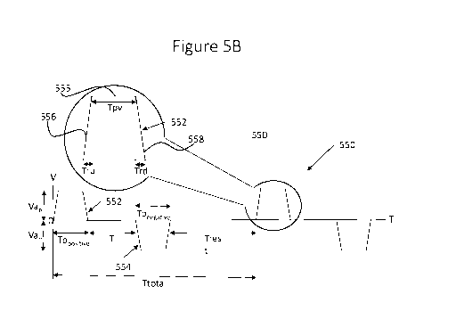
Turning to Figure 5B, it is seen that a signal 550 provided by the inventive
device 100
of Figures 1-3 includes multiple cycles, each cycle being bi-phasic and
including a positive
voltage pulse 552 having a positive voltage and a negative voltage pulse 554
having a negative
11
CA 03032918 2019-02-04
voltage. Each of positive voltage pulse 552 and negative voltage pulse 554 has
a total pulse
time (Tp) (indicated as Tn
rpositive for the positive voltage pulse 552 and as Tpnegative for the
negative voltage pulse 554), which includes a ramp-up time (Tru), a peak-
voltage time (Tpv),
and a ramp down time (Trd). For each of the positive and negative voltage
pulses 552 and 554,
a ramp up segment of the pulse is indicated by reference numeral 556, a ramp
down segment
of the pulse is indicated by reference numeral 558, and a peak voltage segment
of the pulse is
indicated by reference numeral 555. It will be appreciated that the ramp-up
segment 556 of the
positive voltage signal 552 is achieved by the control unit 106 operating
switch 212a. The
ramp down segment 558 may be provided passively, by the switch 212a or
switching
mechanism 210 stopping operation to provide a signal, or may alternately be
provided
actively, by the switch 212a actively lowering the voltage provided by pulse
552.
Similarly, it will be appreciated that the ramp-up segment 556 of the negative
voltage
signal 554 is provided by the control unit 106 operating switch 212b. The ramp
down segment
558 may be provided passively, by the switch 212b or switching mechanism 210
stopping
operation to provide a signal, or may alternately be provided be provided
actively, by the
switch 212b actively increasing the voltage provided by pulse 554.
In some embodiments, the positive voltage pulse 552 has a time-averaged
voltage
amplitude (Vap), over the entire duration (Tpposiiive) thereof, in the range
of 20-90 Volts, and
the negative voltage pulse 554 has a time-averaged voltage amplitude (Van),
over the entire
duration (Tpncgativc) thereof, in the range of -20 ¨ -90 Volts.
The ramp up time (Tru) and ramp down time (Trd) are defined as discussed
hereinabove with respect to Figure 5A. It will be appreciated by people of
skill in the art that
in the positive voltage pulse 552, the peak voltage is a positive voltage, and
as such during the
ramp up time the voltage increases from the baseline voltage, typically zero,
towards the peak
voltage, and during the ramp down time the voltage decreases from the peak
voltage towards
the baseline voltage, whereas in the negative voltage pulse 554 the peak
voltage is a negative
voltage, and as such during the ramp up time the voltage decreases from the
baseline voltage
towards the peak voltage, and during the ramp down time the voltage increases
from the peak
voltage back towards the baseline voltage.
Specifically, it is a particular feature of the teachings herein that the
positive voltage
pulse 552 attains at least 80% of the time-averaged voltage amplitude (Vap)
within a time
12
CA 03032918 2019-02-04
(T80) of 70-150 nanoseconds, and/or that the positive voltage pulse 552
increases by at least
20 Volts within 70 nanoseconds. Similarly, the negative voltage pulse 554
attains at least 80%
of the negative time-averaged voltage amplitude (Van) within a time (T80) of
70-150
nanoseconds, and/or decreases by at least 20 Volts within 70 nanoseconds.
In some embodiments, T(80) is at least 75 nanoseconds or at least 80
nanoseconds. In
some embodiments, T(80) is at most 140 nanoseconds, at most 130 nanoseconds,
at most 120
nanoseconds, at most 115 nanoseconds, or at most 110 nanoseconds.
In some embodiments, the positive voltage pulse 552 increases by at least 30
Volts, by
at least 40 Volts, or by at least 50 Volts, within 70 nanoseconds. In some
embodiments, the
negative voltage pulse 554 decreases by at least 30 Volts, by at least 40
Volts, or by at least 50
Volts, within 70 nanoseconds.
In some embodiments, the positive voltage pulse 552 attains at least 80%, at
least 85%,
at least 90%, at least 95%, or substantially 100% of the time-averaged voltage
amplitude (Vap)
within 70-150 nanoseconds, 75-140 nanoseconds, 80-130 nanoseconds, 80-120
nanoseconds,
or 80-110 nanoseconds.
In some embodiments, the negative voltage pulse 554 attains at least 80%, at
least
85%, at least 90%, at least 95%, or substantially 100% of the time-averaged
voltage amplitude
(Vaõ) within 70-150 nanoseconds, 75-140 nanoseconds, 80-130 nanoseconds, 80-
120
nanoseconds, or 80-110 nanoseconds.
As such, in some embodiments, the ramp-up time (Tru), which is controlled by
switching mechanism 210, is in the range of 50-200 nanoseconds, 60-175
nanoseconds, 70-
150 nanoseconds, 75-140 nanoseconds, 80-130 nanoseconds, 80-120 nanoseconds,
or 80-110
nanoseconds.
As is clearly understood from comparison of Figures 5A and 5B, the ramp-up
time
(Tru) during which the prior art pulse 502 ramps up to reach the peak voltage,
is significantly
longer than the ramp-up time during which the positive voltage pulse 552 of
the present
invention reaches the peak voltage. The inventor has surprisingly discovered
that the short
ramp-up time is associated with improved alleviation of pain and discomfort,
including
alleviation of physiological pain and/or of instrumentally induced pain, if
such exists.
More specifically, the inventor has found that at a ramp-up time of less than
70 ns, the
instrumentally-induced pain greatly increases, and is not sufficiently
compensated for by the
13
CA 03032918 2019-02-04
pain-relief mechanisms of the body. The inventor has further found that at
ramp-up times in
excess of 200 ns, the instrumentally induced pain may be greatly reduced, but
activation of the
pain-relief mechanisms of the body (e.g., generation of opiates or morphine-
like substances) is
also greatly reduced, such that such slow ramp-up times are relatively
inefficacious in
alleviating the pain of the user.
Without wishing to be bound by theory, Applicants believe that the rapid ramp
up of
the signal provided by the present invention at the region of the body at
which pain is felt by
the user, causes the brain to send to that region a significantly increased
amount of opiates or
morphine-like molecules, which provide rapid and effective pain relief to the
area, and which
also provide immediate and substantially complete relief to any pain
experienced by the user
due to provision of the signal, such that the signal does not, in and of
itself, cause the user
pain, and the enhanced presence of opiates or morphine-like molecules in that
area of the body
relieve the previously felt pain for which the user is receiving treatment.
Stated differently, Applicants believe that the provision of the electrical
signals to the
area at which the pain is felt, occupies the pain feeling neurons in the area,
resulting in the
brain providing pain relieving molecules to the area in a quantity which is
sufficient for
effectively eliminating the pain felt by the provision of the signal, if any,
and for relieving the
pain for which treatment is being sought. An intermediate time (Ti), is
defined as the time
between the positive voltage pulse 552 and the negative voltage pulse 554, and
a rest time
(Trest), is defined as the rest time between cycles, or as the time from the
end of the negative
voltage pulse 554 of one cycle and the beginning of the positive voltage pulse
552 of the next
cycle. The total time for each cycle (Ttotal) is defined as Ttotal = Tppositiõ
+ Tpnegative Ti
Trest.
In some embodiments, the frequency of the cycles in signal 550 is in the range
of 60-
150 cycles per second, 70-140 cycles per second, 80-130 cycles per second, or
80-120 cycles
per second. Stated differently, the total time (Ttotal) for each cycle is in
the range of 6.5-16.7
milliseconds, in the range of 7.1-14.3 milliseconds, in the range of 7.7-12.5
milliseconds, or in
the range of 8.3-12.5 milliseconds.
In some embodiments, the total pulse time (Tp) for each of the positive and
negative
voltage pulses 552 and 554 is in the range of 70-130 microseconds, in the
range of 80-120
microseconds, or in the range of 90-110 microseconds. In some embodiments, the
positive
14
CA 03032918 2019-02-04
pulse attains at least 80% of Vap, and/or the negative pulse attains at least
80% of Van, for a
pulse duration within the range of 70-130 microseconds, in the range of 80-120
microseconds,
or in the range of 90-110 microseconds. In some embodiments, the positive
voltage pulse
and/or the negative voltage pulse has a substantially constant voltage
amplitude for a pulse
duration within a range of 70-130 microseconds, 80-120 microseconds, or 90-110
microseconds.
In some embodiments, the intermediate time (Ti) for each cycle is at least 0.1
millisecond, at least 0.2 milliseconds, at least 0.3 milliseconds, or at least
0.4 milliseconds. In
some embodiments, the intermediate time (Ti) for each cycle is at most 1
millisecond, at most
0.9 milliseconds, at most 0.8 milliseconds, or at most 0.7 milliseconds.
In some embodiments, the rest time (Trest) between the end of a final voltage
impulse
of a particular cycle, and the beginning of an initial voltage impulse of a
subsequent, adjacent
particular cycle is at least 0.3 milliseconds, at least 0.4 milliseconds, or
at least 0.5
milliseconds. In some embodiments, Trest for each cycle is at most 1
millisecond, at most 0.9
milliseconds, at most 0.8 milliseconds, or at most 0.7 milliseconds.
In some embodiments, the negative voltage pulse 554 is area-symmetric with
respect
to the positive voltage pulse 552, within 10 area%, within 5 area%, within 2
area%, or within
1 area%. Stated differently, the cumulative charge provided by the negative
voltage pulse 554
to the surface of the body of the user is within 10%, 5%, 2%, or 1% of the
cumulative charge
provided by the positive voltage pulse 552 to the surface of the body of the
user. As such, in
some embodiments, each cycle in the signal 550 is a balanced bi-phasic cycle.
Reference is now made to Figure 6, which is a schematic illustration of a
series of
electrical signals according to an embodiment of the teachings herein. As
shown, an electrical
signal 600 includes a plurality of cycles 602, each including a positive
voltage pulse 604
having a similar structure to that of positive voltage pulse 552 of Figure 5B
and a negative
voltage pulse 606 having a similar structure to that of negative voltage pulse
554 of Figure 5B.
In each cycle 602, the ramp-up time (Tru) of the positive voltage pulse is
substantially
equal to the ramp up time of the negative voltage pulse, but the ramp up times
are different
between cycles. More specifically, with each cycle 602 the ramp up time Tru
decreases or
gradually decreases, until the ramp-up time of 70-150 nanoseconds, described
in detail with
respect to Figure 5B, is reached.
CA 03032918 2019-02-04
As such, in the first cycle 602a, or in a first sequence of such cycles, the
positive and
negative voltage pulses have a relatively long ramp up time, which may, in
some
embodiments, be greater than 100 nanoseconds, or in the range of 100-200
nanoseconds. In
subsequent cycles, or sequences of cycles, the positive and negative voltage
pulses have
increasingly shorter ramp-up times. For example, the second cycle 602b, or
second sequence
of cycles, may have a ramp-up time of 100 nanoseconds, the third cycle 602c,
or third
sequence of cycles, may have a ramp up time of 95 or 90 nanoseconds, and so
on, until the
ramp up time reaches the desired ramp-up time, for example 80 nanoseconds,
shown in the
two last illustrated cycles, 602e and 6021 It will be appreciated that in
accordance with the
teachings herein, any additional cycles following cycle 602f will continue to
have a ramp-up
time in the range of 70-150 nanoseconds, as described hereinabove.
Without wishing to be bound by theory, the inventor believe that the signal
shown in
Figure 6 would eliminate any residual pain caused by provision of the signal,
in that such pain
would not be generated due to the relatively long ramp-up time of the first
cycle 602a, and
that that the pulses provided in cycle 602a would cause the body to deliver to
the region at
which the electrodes are placed sufficient pain relieving molecules, such as
opiates or
morphine-like molecules, to relieve any pain felt by the somewhat shorter ramp
up time of the
pulses in signal 602b. The inventor believes that this behavior would continue
and sufficient
pain relieving molecules would be present at the beginning of each cycle,
other than cycle
602a, such that no pain would be felt by the user due to the provision of the
signal ¨ in cycle
602a because the ramp up time is sufficiently long so as not to cause pain as
is known in the
art, and in the following cycles because sufficient pain relieving molecules
will have been
delivered to the vicinity of the electrodes and would alleviate any pain
potentially caused by
the provision of the signals.
A device such as the devices described in conjunction with any of Figures 1-3
may be
provided to a user. In typical use, the user or clinician attaches the
electrodes 102 to a surface
of the body, in a general area where pain is experienced. In some embodiments,
the pain is a
menstrual or pre-menstrual pain, and the user attaches the electrodes to the
skin surface at or
near an abdominal region of the body, where the pain is experienced.
Once the electrodes are attached to the skin of the user, the user uses the
user interface
109 to activate the device 100, such processor 106 activates signal generator
104 to provide
16
CA 03032918 2019-02-04
signals as described in Figure 5B to the skin surface of the user's body,
thereby to relieve the
pain. In some embodiments, the user may then provide input to processor 106
via input
module 108 and/or user interface 109 thereof, for example to indicate whether
the treatment is
helping, to increase or decrease the frequency or intensity of the signals, or
to terminate
activity of device 100.
In some embodiments, the user may wear the device, before, after, and during
operation thereof, for example clipped to a garment worn by the user. In such
embodiments,
the device 100 is portable, and as such may be used in the operative mode,
while worn by the
user and/or solely using the on-board power supply, when the user is moving
around, without
being tied to a specific location, for a duration of at least 5 minutes, at
least 10 minutes, at
least 15 minutes, or at least 30 minutes.
As used herein in the specification and in the claims section that follows,
the term "or"
is considered as inclusive, and therefore the phrase "A or B" means any of the
groups "A",
"B", and "A and B".
As used herein in the specification and in the claims section that follows,
the terms
"pulse", "signal", and "impulse" all relate to an electrical signal, for
example applied via an
electrode.
As used herein in the specification and in the claims section that follows,
the term
"cycle" relates to a repetitive or semi-repetitive bi-phasic segment of an
electrical voltage
signal, as is generally recognized and understood in the art. Represented on a
voltage vs. time
plot, a "cycle" typically consists of a positive voltage pulse, a negative
voltage pulse, any
intermediate time (Ti) therebetween, and the rest time (Trest) between the end
of a final
voltage impulse of a particular cycle, and the beginning of an initial voltage
impulse of a
subsequent, adjacent particular cycle. As a matter of convention, Trest > Ti.
As used herein in the specification and in the claims section that follows,
the term
"positive voltage pulse" relates to an electrical pulse providing an
electrical signal having
positive voltage, whether an absolute positive voltage or a positive voltage
relative to a
baseline voltage. Typically the baseline voltage is zero.
As used herein in the specification and in the claims section that follows,
the term
"negative voltage pulse" relates to an electrical pulse providing an
electrical signal having
negative voltage, whether an absolute negative voltage or a negative voltage
relative to a
17
CA 03032918 2019-02-04
baseline voltage. Typically the baseline voltage is zero.
As used herein in the specification and in the claims section that follows,
the term
peak voltage" relates to a voltage within 15%, within 10%, within 5%, within
3%, or within
1% of the maximal voltage in the pulse. The peak voltage of a positive voltage
pulse is a
positive voltage and the peak voltage of a negative voltage pulse is a
negative voltage.
As used herein in the specification and in the claims section that follows,
the term
peak voltage time" relates to the duration in which the pulse attains the peak
voltage.
As used herein in the specification and in the claims section that follows,
the term
"maximal voltage" relates to the highest voltage attained by a positive
voltage pulse, or the
lowest voltage attained by a negative voltage pulse, during the entire
duration of the pulse.
As used herein in the specification and in the claims section that follows,
the term "ramp-up
time" relates to the time in which the voltage of the pulse, or the absolute
value or magnitude
of the voltage of the pulse, increases to at least 80%, at least 85%, at least
90%, at least 95%,
or substantially 100%, of the peak voltage.
As used herein in the specification and in the claims section that follows,
the term
"ramp-down time" relates to the time in which the voltage of the pulse, or the
absolute value
or magnitude of the voltage of the pulse, decreases by at least 80%, at least
85%, at least 90%,
at least 95%, or substantially 100%, of the peak voltage, or to be within 20%,
within 15%,
within 10%, within 5%, or substantially equal to, the baseline voltage.
As used herein in the specification and in the claims section that follows,
the term
"timed-averaged voltage amplitude" relates to the average voltage amplitude
over a
predetermined time duration, for example the average voltage amplitude for a
positive or
negative voltage pulse over the entire duration thereof, or over a segment of
the positive or
negative voltage pulse at which a peak voltage amplitude is attained. Due to
the extremely
swift ramp-up times utilized in the present invention, the "timed-averaged
voltage amplitude"
of the "plateau" of such a pulse may be approximated by the "timed-averaged
voltage
amplitude" of the pulse, or the "timed-averaged voltage amplitude" of the
portion of the pulse
in which voltage is applied, e.g., taken over the ramp-up time (Tru) and the
peak-voltage time
(Tpv).
As used herein in the specification and in the claims section that follows,
the term
"substantially constant voltage amplitude", with regard to a voltage pulse, or
a portion thereof,
18
CA 03032918 2019-02-04
relates to a voltage amplitude being constant, within a deviation of 15%, 10%,
5%, 3%, or 1%.
As used herein in the specification and in the claims section that follows,
the term
area-symmetric" relates to two voltage pulses, such as a positive voltage
pulse and a negative
voltage pulse, which, when an amplitude thereof is plotted relative to time
and relative to a
baseline voltage or relative to a zero voltage, the areas trapped between the
plots of the two
pulses' amplitudes and of the baseline voltage are equal, or are within 10%,
within 5%, within
2%, within 1%, of one another.
As used herein in the specification and in the claims section that follows,
the term
"balanced cycle" relates to a cycle including a positive voltage pulse and a
negative voltage
pulse, such that the charge provided by the positive and negative voltage
signals is equal, or is
within 15%, within 10%, within 5%, within 3%, or within 1% of one another.
As used herein in the specification and in the claims section that follows,
the term "A
is electrically downstream to B" relates to an electrical component A which
receives, as input,
an electrical signal provided by an electrical component B, either directly or
via additional
electrical components located electrically between electrical components B and
A.
As used herein in the specification and in the claims section that follows,
the term
"portable" relates to a device which can be ported, or moved around, while in
its operative
mode using an on-board power supply, to a distance greater than 10 meters
and/or for a
duration of at least 5 minutes, at least 10 minutes, at least 15 minutes, or
at least 30 minutes,
without requiring a wired or wireless connection to a power source or to a
communication
module such as a Wi-Fi transceiver.
As used herein in the specification and in the claims section that follows,
the term
"instrumentally induced pain" relates to any pain or discomfort caused by
operation of the
device or instrument on or in the body of the user to provide treatment
thereto.
As used herein in the specification and in the claims section that follows,
the terms
"physiological pain" and "physiologically induced pain" relate to pain caused
by the
physiology of the user, irrespective of the presence or operation of a device
or instrument on
or in the body of the user.
It will be appreciated that certain features of the invention, which are, for
clarity,
described in the context of separate embodiments, may also be provided in
combination in a
single embodiment. Conversely, various features of the invention, which are,
for brevity,
19
CA 03032918 2019-02-04
described in the context of a single embodiment, may also be provided
separately or in any
suitable sub-combination. Similarly, the content of a claim depending from one
or more
particular claims may generally depend from the other, unspecified claims, or
be combined
with the content thereof, absent any specific, manifest incompatibility
therebetween.
As used herein, unless otherwise stated, the terms "substantially" and
"about", when
modifying a condition or relationship characteristic of a feature or features
of an embodiment
of the present technology, are to be understood to mean that the condition or
characteristic is
defined to within tolerances that are acceptable for operation of the
embodiment for an
application for which it is intended.
Although the invention has been described in conjunction with specific
embodiments
thereof, it is evident that many alternatives, modifications and variations
will be apparent to
those skilled in the art. Accordingly, it is intended to embrace all such
alternatives,
modifications and variations that fall within the spirit and broad scope of
the appended claims.