Note: Descriptions are shown in the official language in which they were submitted.
- 1 -
RADIO SYSTEM USING NODES
CROSS-REFERENCE TO RELATED APPLICATIONS
[0001] This application claims priority to U.S. provisional applications no.
62/379,601,
filed August 25, 2016, and no. 62/396,181, filed September 18, 2016.
BACKGROUND OF THE INVENTION
[0002] Field of the Invention
[0003] The present invention relates to radio mesh systems using satellites in
random
orbits in communication with ground stations including ground-based receivers
and transmitters for cellular telephone communication and Internet
connections,
and more particularly, to systems and methods of automatically establishing
radio routes between ground stations using one or more unguided or
substantially unguided satellites deployed randomly or quasi-randomly in low-
earth orbits.
[0004] Description of Related Art
[0005] A brief history of certain aspects of cellular telephony relevant to
the present
disclosure is set forth in U.S. Patent No. 5,793,842, which names as an
inventor
Jerry R. Schloemer, who is also the present inventor. One early system
architecture, still in use today, involved a limited number of tower-mounted
transceivers ("drops") and plural mobile radios ("cellular telephones"). In
these
early systems, and still in some cases today, a central computer controlled
communications between land lines connected to the towers and the
CA 3032969 2019-03-29
CA 03032969 2019-02-04
WO 2018/039292 PCT/US2017/048110
- 2 -
mobile radios. Implementing this system architecture required significant
investment in
infrastructure and computing power, especially as the increasing popularity
and technical
capabilities of cellular telephones necessitated increased system capacity and
sophistication. An alternate system architecture involved using radio
transceivers
("nodes") mounted on existing structures, such as buildings and telephone
poles. These
architectures use nodes capable of receiving and transmitting signals to and
from cellular
telephones along a radio route among the nodes to drops at selected nodes.
This came to
be called a mesh network, an early example being the system disclosed in Cox,
Donald C.,
"Wireless Network Access for Personal Communications," IEEE Communications
Magazine
(Dec. 1992), pp 96415.
[0006] A particular challenge in implementing mesh systems was how to
determine the best
available radio routes for interconnecting the nodes. Generally, early mesh
systems still
required a central computer to make routing determinations, which added to
system
complexity and cost Other approaches, such as that described in U.S. Patent
No. 4,937,822
to Weddle et al., involved a mesh system in which routes would be established
automatically, that is, without a central computer. However, Weddle disclosed
such a
system only in a mesh in which the nodes are laid out in a regular rectangular
grid and
radio routing links can only be between nodes orthogonally adjacent to each
other (that
is, cater-corner links between nodes would not be permitted). The shortcomings
of such a
system will be immediately apparent to those skilled in the art, if for no
other reason than
in a real-world setting it would be very difficult, if not impossible, to
distribute nodes in a
strictly orthogonal, uniformly-spaced rectangular grid over a wide enough area
to make
the system practicable. Moreover, Weddle does not disclose in detail any
algorithm by
which the nodes would actually create a preferred radio route,
-3-
100071 Against that background the present inventor's U.S. Patent No.
5,793,842
disclosed a system and method of creating radio routes through a mesh of nodes
that were not limited in their placement and did not require a central
computer.
The systems and methods described in detail further below in connection with
the present invention take advantage of technology described in U.S. Patent
No.
5,793,842 relating to the creation of radio routes through plural, randomly
located nodes and the transmission of communications using those routes.
[0008] The inventor improved on that technology in his later U.S. Patent No.
6,459,899, which, among other things, describes a system that uses nodes with
directional antennas to improve the route creation and communication
transmission capabilities of the earlier system. This improvement solves
complex issues presented by using nodes with directional antennas in the
systems and methods described in the '842 patent, and thus takes advantage of
the higher quality radio links achievable with directional antennas. The
present
invention also uses the technology disclosed in the '899 patent.
100091 Before the inventor's approach to creating routes through a radio mesh
network
with randomly distributed nodes and no central computer, others were proposing
ways to provide worldwide cellular coverage using satellites for call
transmission between earth-based originating and destination drops. An
example of a satellite system that was actually commercialized is disclosed in
various patents such as U.S. Patent No. 5,274,840 to Schwendeman and U.S.
Patent No. 5,410,728 to Bertiger et al., both of which are assigned to
Motorola,
Inc. This system utilized satellites evenly distributed in a
CA 3032969 2019-03-29
CA 03032969 2019-02-04
WO 2018/039292 PCT/US2017/048110
- 4 -
predetermined number of polar orbits as transceivers for signals between
satellites and
between satellites and transceivers on the ground. A sufficient number of
satellites is used
to provide coverage of the entire globe. However, in practice this system,
which was
commercialized by Iridium, had numerous drawbacks. One was that each satellite
needed
onboard thrusters, rocket fuel, and navigational hardware to maintain its
desired orbit.
This increased satellite size and weight which increased the launch cost, as
well as
increasing the cost of the satellite itself. Also, to account for inevitable
satellite failures,
extra satellites would have to be maneuvered into a failed satellite's orbit,
thus increasing
the cost of the entire system by requiring extra satellites and their
concomitant high
manufacturing and launch costs. See, for example, "Iridium Satellite
Constellation,"
Wikipedia, https://en.wikipedia.org/wiki/Iridium (last visited May 9,2017).
Ground-based orbit and attitude control using complex computer technology
further
increased system costs. In the end, its drawbacks made the system commercially
unviable
for mass market applications, although it is believed to have found use in
specialized
areas such as military applications and reporting by journalists from remote
areas.
[0010] In addition to maintaining each Iridium satellite in a particular
orbital position relative to
the earth and other satellites, the attitude of each satellite also had to be
maintained
within certain tolerances so that its antennas would be oriented for effective
satellite-
satellite and satellite-ground radio communications. One way of providing
attitude
control was using onboard thrusters, which present the drawbacks already
discussed.
Various mechanically-based inertial attitude control systems have been
proposed, such as
those described in U.S. Patents No. 3,017,777 and No. 8,164,294, and in
Chabot, J. A., "A
Spherical Magnetic Dipole Actuator for Spacecraft Attitude Control," Thesis
for M.S. in
Aerospace Engrg. Sciences, Univ. of Colorado, 2015. However, it is believed
'that these
types of systems would not perform any better than rocket-based attitude
control, while
- 5 -
. their
mechanical complexity aid onboard control systems would preclude
significant savings in weight as compared to rocket-based attitude control.
[0011] The present inventor disclosed in his U.S. Patent No. 5,566,354 a
satellite
cellular telephone system that improved on the Motorola-Iridium approach.
The inventor's improved approach allowed the satellites to occupy random
orbits. This eliminated the orbital control components of satellite systems
that relied on each satellite being in a known location relative to the
others,
such as the Motorola-Iridium system or the wireless telephone! satellite
system disclosed in U.S. Patent No. 5,303,286. However, the random-orbit
system described in the '354 patent has certain drawbacks, one of which is
that the satellites still require attitude control to insure that the
satellite
antennas point in the correct directions. Nor, as discussed in detail further
below, does it have the advantages of a true mesh system, as that term is
used in this description.
[0012] Aside from the rapid spread of cellular telephone usage around the
world
in recent years, access to the Internet through computers and smartphones
has become a necessity for businesses and individuals alike. It is difficult
to
do business or manage personal affairs effectively without access to
Internet-based resources like email, electronic banking, investigative/search
services, and many others. In addition, social media providers like
FacebookTm and TwitterTm can only exist in areas of the world that provide
Internet access. A satellite-based system presents an ideal way of making
the Internet and cellular telephone service available in remote areas without
blanketing a country with towers or installing land-based radio mesh nodes
across vast areas. However, known satellite systems suffer from numerous
drawbacks, some of which are discussed above, and none has been
successfully commercialized to date. In fact, a low-cost satellite system
would have the potential to replace tower-based systems and ground-based
mesh systems altogether.
CA 3032969 2020-03-09
CA 03032969 2019-02-04
K.. WO 2018/039292 PCT/US2017/048110
- 6 -
SUMMARY OF THE INVENTION
[0013] It is an object of the present invention to provide a radio
communication system
comprising a plurality of satellites capable of establishing radio links
between orbiting
satellites and between the satellites and ground-based stations without
requiring the
satellites to be maintained in predetermined orbits or in predetermined
attitudes relative
to each other or the earth. In a preferred embodiment there are a sufficient
number of
satellites to provide a satellite mesh that ensures almost to a certainty that
any spot on
the earth's surface will be within sight of at least one satellite at all
times. One specific
embodiment utilizes at least 200 satellites.
[0014] One aspect of the invention rests in part on incorporating in each such
satellite a plurality
of antennas capable of transmitting and receiving in all directions. A radio
link can be
created when a radio beam transmitted from an antenna in one satellite is
received by an
antenna in another satellite. This is sometimes referred to herein as a "beam
match." The
inventor recognized that using a unique antenna arrangement and uniquely coded
radio
transmissions from the satellites and ground stations, and treating both as
nodes in a
mesh, would enable a radio route to be established between ground stations by
assembling radio links via one or more of the satellites. One insight that led
to this aspect
of the invention is that the satellites' attitudes and relative positions
change sufficiently
slowly as compared to the time that it takes the on-board computers in each
satellite to
calculate a radio route. Accordingly, once the radio route is established,
communications
("calls") between the ground stations via one or more of the satellites are
not normally
disrupted or, in the event that an existing route is disrupted as a satellite
moves or
tumbles, a new radio route can be established "on the fly" with the same or
different
satellites while the call is in progress. As used in the description that
follows, a "call" is a
communication of content (digital or otherwise) over a radio route between
satellites or
CA 03032969 2019-02-04
WO 2018/039292 PCT/US2017/048110
- 7 -
between a satellite and a ground station, unless otherwise indicated
explicitly or by
context. While not limited as such, the systems described herein are
particularly well
suited for the transmission of data in packets, defined here in the generally
accepted
sense as a collection of digital data with a portion representing the content
of the
transmission (sometimes referred to as the "payload"), and a control portion
(sometimes
referred to as a "header" or "trailer"), which contains information enabling
the payload to
be delivered successfully, such as source and destination addresses, error
detection codes,
and sequencing information.
[0015] In one of its more general aspects the present invention uses a unique
satellite
construction with on-board computers that can perform calculations and select
antennas
to create radio routes between ground stations via one or more satellites
virtually in real
time as the satellites move in uncontrolled orbits with no attitude control,
The radio
routes are determined by algorithms executed by the computers in the
satellites, so that a
central computer is not needed to specify which satellite or satellites will
comprise an
optimum radio route between ground stations.
[0016] One embodiment of the invention uses the disclosed satellite mesh to
create an optimum
radio route that comprises a single satellite that provides a radio route
between two
ground-based transceivers. The unique satellite design described herein
enables a
single-satellite route to be maintained even as the satellite tumbles with no
attitude
control or if conditions change so that another satellite in sight of the
ground-based
transceivers will provide a better radio route because the first satellite
drifted out of
range or became inoperative for some reason.
[0017] A particular advantage of the system disclosed herein is that in a
preferred embodiment it
provides the above features and those described in more detail below by
blanketing the
earth with lightweight, battery-powered satellites that reduce launch costs
and eliminate
- 8 -
the necessity for complex and costly control systems for maintaining the
satellites in particular orbits and in particular attitudes. Another aspect of
the invention uses ground stations with an antenna arrangement different
from that used in the satellites, since the limitations on satellite weight,
size,
and power do not apply to the ground stations. This means that the ground
stations can have a greater antenna density (more antenna beams over a
given spherical area) and use antennas with more power (gain), thus
virtually ensuring that data communications will be possible between any
two ground stations.
[00181 Another embodiment of the invention enhances the ability of the
satellites
to establish radio links between satellites and between a satellite and a
ground station by using satellites that spin or rotate about an axis. This
increases the probability of creating a beam match between two satellites
because each satellite is likely to "see" more antennas on other satellites
during a given period of time. This enables the use of higher-gain antennas
with correspondingly narrower beam widths, thus increasing the strength
of the radio links and the reliability of call transmissions. Typically, the
satellites are deployed with a predetermined angular velocity, which may
be different for different satellites. In one variation of this embodiment,
the
system includes satellites that rotate in opposite directions. Further
considerations for realizing this embodiment are discussed in the detailed
description that follows.
[0019] In one aspect of the invention, there is provided a radio
communications
system including multiple satellites orbiting the earth in random orbits for
providing a radio route for data communications between transceivers at
two ground station locations, each satellite and ground station including a
node of the system, wherein each of a plurality of the satellites includes: a
plurality of satellite antennas for receiving radio signals from a plurality
of
other nodes and for transmitting radio signals; antenna pairing circuitry for
CA 3032969 2020-03-09
- 8a -
storing address information identifying another node from which the
satellite received a routing signal and identifying the satellite antenna on
which the satellite received the routing signal; and route creation circuitry
for transmitting routing signals from a plurality of the satellite antennas,
wherein the routing signals include (i) linking information identifying the
satellite, and (ii) a quality of the received routing signal indicating a
suitability of the satellite and the other node as a radio link in the radio
route between the two ground station locations.
[0020] In another aspect of the invention, there is provided a method for
creating a
radio communication route for data communications from a receiving
ground station to a sending ground station, wherein the ground stations
include a plurality of ground station directional antennas for transmitting
and receiving radio signals, the method including: (a) providing multiple
satellites orbiting the earth in random orbits, wherein each of a plurality of
the satellites includes a plurality of satellite directional antennas for
transmitting and receiving radio signals; (b) receiving at a satellite antenna
of at least one satellite an initial information signal transmitted from an
antenna at a sending ground station; (c) storing at any satellite receiving
the
initial information signal at least (i) address information identifying the
ground station from which the initial information signal was received, and
(ii) the satellite antenna on which the initial information signal was
received; (d) transmitting linking information signals from a plurality of the
antennas of at least one satellite receiving the initial information signal,
wherein the linking information signals include (i) linking information
identifying the satellite, and (ii) a quality of the received initial
information
signal indicating a suitability of the satellite and the sending ground
station
as a radio link in a radio route between the ground stations; and (e) storing
at a receiving ground station receiving at least one linking information
signal (i) address information identifying the satellite transmitting the
linking information signal, (ii) the receiving ground station antenna on
CA 3032969 2020-03-09
- 8b -
which the linking information signal was received, and (iii) a quality of the
initial information signal received at the satellite transmitting the linking
information signal; and (f) determining a quality of a radio route for data
communications from the receiving ground station to the sending ground
station via a particular satellite based on (i) a quality of the received
linking
information signal indicating a suitability of the receiving ground station
and the particular satellite as a radio link in a radio route between the
ground stations, and (ii) the quality of the initial information signal.
[0021] In yet another aspect of the invention, there is provided a radio
communication route for data communication from an originating ground
station to a destination ground station, the route including at least one of
multiple satellites orbiting the earth in random orbits that communicate
with the ground stations, each including a plurality of directional antennas
for receiving radio signals from multiple directions and transmitting radio
signals in multiple directions, wherein the satellite includes: antenna
pairing
circuitry for storing address information identifying a destination ground
station from which an initial information signal was transmitted and
antenna information identifying the satellite antenna on which the initial
information signal was received; and route creation circuitry for
transmitting linking information signals from a plurality of the satellite
antennas, the linking information signals including linking information
identifying the satellite to an originating ground station receiving the
linking information signal on one of the ground station antennas, whereby
data transmissions received at the originating ground station and
designating a particular destination ground station are transmitted by the
originating ground station using the ground station antenna on which the
linking information was received and the satellite transmits the data
transmission using the satellite antenna identified by the stored antenna
information.
CA 3032969 2020-03-09
- 9 -
[0022] In a further aspect of the invention, there is provided a method of
communicating data via a radio route including at least one radio link
between two satellites orbiting the earth, wherein at least one of the
satellites is rotating and includes at least two directional antennas for data
communications with another satellite.
[0023] In yet another aspect of the invention, there is provided a radio
communications system including multiple satellites orbiting the earth for
providing a radio route for data communications between transceivers at
two ground station locations, each satellite and ground station including a
node of the system, wherein each of a plurality of the satellites includes: a
plurality of satellite antennas for receiving radio signals from a plurality
of
other nodes and for transmitting radio signals; antenna pairing circuitry for
storing address information identifying another node from which the
satellite received a routing signal and identifying the satellite antenna on
which the satellite received the routing signal; and route creation circuitry
for transmitting routing signals from a plurality of the satellite antennas,
wherein the routing signals include (i) linking information identifying the
satellite, and (ii) a quality of the received routing signal indicating a
suitability of the satellite and the other node as a radio link in the radio
route between the two ground station locations.
[0024] In another aspect of the invention, there is provided a method for
creating a
radio communication route for data communications from a receiving
ground station to a sending ground station, wherein the ground stations
include a plurality of ground station directional antennas for transmitting
and receiving radio signals, the method including: (a) providing multiple
satellites orbiting the earth, wherein each of a plurality of the satellites
includes a plurality of satellite directional antennas for transmitting and
receiving radio signals; (b) receiving at a satellite antenna of at least one
satellite an initial information signal transmitted from an antenna at a
CA 3032969 2020-03-09
- 10 -
sending ground station; (c) storing at any satellite receiving the initial
information signal at least (i) address information identifying the ground
station from which the initial information signal was received, and (ii) the
satellite antenna on which the initial information signal was received; (d)
transmitting linking information signals from a plurality of the antennas of
at least one satellite receiving the initial information signal, wherein the
linking information signals include (i) linking information identifying the
satellite, and (ii) a quality of the received initial information signal
indicating a suitability of the satellite and the sending ground station as a
radio link in a radio route between the ground stations; and (e) storing at a
receiving ground station receiving at least one linking information signal (i)
address information identifying the satellite transmitting the linking
information signal, (ii) the receiving ground station antenna on which the
linking information signal was received, and (iii) a quality of the initial
information signal received at the satellite transmitting the linking
information signal; and (f) determining a quality of a radio route for data
communications from the receiving ground station to the sending ground
station via a particular satellite based on (i) a quality of the received
linking
information signal indicating a suitability of the receiving ground station
and the particular satellite as a radio link in a radio route between the
ground stations, and (ii) the quality of the initial information signal.
[0025] In another aspect of the invention, there is provided a radio
communication
route for data communication from an originating ground station to a
destination ground station, the route including at least one of multiple
satellites orbiting the earth that communicate with the ground stations, each
including a plurality of directional antennas for receiving radio signals from
multiple directions and transmitting radio signals in multiple directions,
wherein the satellite includes: antenna pairing circuitry for storing address
information identifying a destination ground station from which an initial
information signal was transmitted and antenna information identifying the
CA 3032969 2020-03-09
- 11 -
satellite antenna on which the initial information signal was received; and
route creation circuitry for transmitting linking information signals from a
plurality of the satellite antennas, the linking information signals including
linking information identifying the satellite to an originating ground station
receiving the linking information signal on one of the ground station
antennas, whereby data transmissions received at the originating ground
station and designating a particular destination ground station are
transmitted by the originating ground station using the ground station
antenna on which the linking information was received and the satellite
transmits the data transmission using the satellite antenna identified by the
stored antenna information.
[0026] These and other aspects and features of the invention and embodiments
thereof will be covered in more detail as this description proceeds.
[0027] This Summary is provided solely to introduce in a simplified form a
selection of concepts that are described in detail further below. It is not
intended necessarily to identify key or essential features of the subject
claimed herein, nor is it intended to be used an aid in determining the scope
of the claimed subject matter.
CA 3032969 2020-03-09
- 12 -
BRIEF DESCRIPTION OF THE DRAWINGS
[0028] The objects of the invention will be better understood from the
detailed
description of us preferred embodiments which follows below, when taken
in conjunction with the accompanying drawings, in which like numerals
and letters refer to like features throughout. The following is a brief
identification of the drawing figures used in the accompanying detailed
description.
[0029]
[0030] FIGURES 1 and 2 illustrate certain geometric principles underlying the
space-based radio systems disclosed and claimed herein.
[0031] FIGURE 3 schematically depicts an embodiment of a satellite suitable
for
use in the space-based radio systems disclosed and claimed herein.
[0032] FIGURE 4 is a representation of various operational components of the
satellite depicted in FIGURE 3.
[0033] FIGURE 5 illustrates an embodiment of a process using a single
satellite for
creating a radio route between two ground stations.
[0034] FIGURE 6 illustrates how a satellite radio mesh system as described
herein
using a single satellite can be used to provide radio routes within a
prescribed geographical area such as the country of Egypt.
[0035] FIGURE 7 illustrates the relation between the distance separating two
points
on the earth's surface and the overlapping area of two intersecting circles
centered on the respective points.
CA 3032969 2020-03-09
- 13 -
[0036] FIGURE 8, comprising FIGURES 8A, 8B, and 8C, schematically depicts
rotating
satellites in accordance with an alternate embodiment of a system using
satellites in random orbits.
[0037] One skilled in the art will readily understand that the drawings are
not strictly
to scale, but nevertheless will find them sufficient, when taken with the
detailed descriptions of preferred embodiments that follow, to make and use
the present invention.
DETAILED DESCRIFi ____________ ION OF PREFERRED EMBODIMENTS
[0038] The detailed description that follows is intended to provide specific
examples
of particular embodiments illustrating various ways of implementing the
claimed subject matter. It is written to take into account the level of
knowledge
of one of ordinary skill in the art to which the claimed subject matter
pertains.
Accordingly, certain details may be omitted as being unnecessary for enabling
such a person to realize the embodiments described herein. It will also be
understood that terms indicating direction or orientation may be used
facilitate
description. The use of such terms does not imply that the claimed subject
matter is limited to a particular orientation of the structure being
described.
[0039] 1. Radio Mesh Concepts and Principles
[0040] The system described herein builds on certain principles underlying the
use of
a plurality of transceivers ("nodes") that can be used to form termination
points
for links in a radio route using one or more of the transceivers. Throughout
the
description herein, the term "radio," ''radio signal," or the like is not
limited to
references to electromagnetic radiation in frequencies commonly referred to as
radio waves. It is meant to encompass electromagnetic radiation of any
frequency capable of transmitting information, including light, microwaves,
VHF ("very high frequency"), UHF ("ultrahigh frequency"), etc. The discussion
in this section describes certain relevant features of prior art arrangements
sometimes referred to as mesh systems, and some of the basic concepts that
represent the
CA 3032969 2020-03-09
- 14 -
significant advances over known mesh technology achieved by the unique
apparatus systems, and methods described herein.
[0041]
[0042] The satellite radio mesh used in the present system supports radio
routes in
which the preferred route between two ground stations includes more than
one satellite and having one or more satellite-to-satellite radio links. It
also
supports radio routes that include a single satellite in communication with
both ground stations. In both embodiments a large number of unique
satellites, described further below, are launched into orbit. The number of
satellites is chosen to provide a high probability that at any given moment, a
point on the surface of the earth will be within line of sight of a certain
number of satellites. For example, U.S. Patent No. 5,566,354 estimates that if
200 satellites were randomly placed at an orbital altitude of 500 miles, a
given point on the earth would "see" on average over time about 12
satellites, or stated another way, the chances of a given spot on the earth
not
being in the line of sight of at least one satellite is only four in
1,000,000.
[0043] FIGURES 1 and 2 illustrate this principle graphically. The approximate
distance DH to the horizon EH from a satellite S at an altitude AL of 500
miles can be calculated according to the formula DH = RR .4_ 500)2_ R91/2,
where R is the radius of the earth E. Depending on the value chosen for R,
DH is about 2000 miles. Thus, the area of coverage AR of a satellite is it x
DH2 12,500,000 sq. mi. Taking the surface area of the earth as 197
million
square
CA 3032969 2020-03-09
- 15 -
miles, each satellite thus "covers" about 6% of the earth's surface, which
means
that on average any one point on the surface will "see" about 12 satellites
(200 x
0.06). Conversely, the chance that a single satellite will not be visible from
any
particular point on the earth is 94%. If there are 200 satellites launched
into
random orbits, the probability that any given point on the earth will not see
at
least one satellite is only 0.94200 0.0004% (that is, four in a million). The
'354
patent includes a table that shows the estimated probability of constant
coverage
over time of a point on the surface for different numbers of satellites.
[0044] It should be noted that the term "random orbits" in the context of the
present
description must be considered in combination with the number of satellites
used in the system. It generally means that a sufficient number of satellites
are
placed into orbits that are initially spaced apart with the goal of maximizing
coverage of the globe. It is not meant to require random distribution in a
pure
mathematical sense. Rather, it is used to indicate that precise positioning of
satellites at particular locations is not required, and that the manner of
placing
them into orbit will take into account the number of satellites comprising the
system and the desired degree of certainty, calculated in accordance with
suitable statistical algorithms, that any given point on the earth's surface
will be
within sight of at least one satellite at all times. (It will be appreciated
that the
system permits different satellites to satisfy that requirement for a given
point as
the satellites' orbits change over time.) For example, known techniques for
generating so-called pseudorandom numbers can be used as a basis for
calculating initial satellite numbers and placement. Other ways of achieving
"random" satellite distribution are described in U.S. Patent No. 5,566,354 in
the
"Satellite Launch" section. The number of satellites launched into orbit will
preferably be in excess of a calculated number to enable continued full earth
coverage by accounting for a certain
CA 3032969 2019-03-29
CA 03032969 2019-02-04
T.
WO 2018/039292 PCT/US2017/048110
- 16 -
number of satellite failures over time, or for satellites that are destroyed
by reentry into
the earth's atmosphere because of orbit decay or damaged by space debris.
[0045] Another important feature of the system described and claimed herein is
that the
satellites do not require active, onboard attitude control. Thus, they do not
require any
moving parts, mechanisms, or propulsion systems, which reduces satellite
weight and
cost, and they can be released into orbit without regard to their angular
orientation. It is
expected that satellites can deployed from a launch vehicle such as a space
station or the
like. It will be preferable in some embodiments of the system described herein
to attempt
to deploy them with as little angular velocity as possible, but no special
effort is required
in that regard. Systems in accordance with such embodiments will create radio
routes
even if the satellites "tumble," meaning that each satellite can change its
angular
orientation at a rate different from other satellites, or not at all, as it
orbits. Stated another
way, the satellites are neither in prescribed orbits nor in controlled
orientations. It is
possible in some implementations to distribute the mass of the satellites
and/or
components comprising ferromagnetic materials to maintain a certain amount of
tumbling as they orbit the earth and interact with its gravitational and
magnetic fields. In
addition, the size and orientation of solar panels used to produce electrical
power (see
FIGURES 3 and 4) can be judiciously selected to employ the kinetic energy of
photons
striking the panels to provide forces that influence the tumbling motion of
the satellites. If
desired, each satellite can include tracking telemetry to detect when its
orbit is decaying
and it needs to be replaced, and to comply with any national or international
protocols
applicable to orbiting bodies. However, it is expected that it will be
relatively simple and
inexpensive to provide such telemetry.
[0046] In another embodiment the satellites are deployed in random orbits with
an angular
velocity imparted to them. In the manner described further below, this enables
the use of
CA 03032969 2019-02-04
WO 2018/039292 PCT/US2017/048110
- 17 -
higher gain antennas to create beam matches even though the radio beams may be
narrower, This enhances the ability of the system to more readily create radio
routes
using more than one satellite, which has the potential in some settings to
increase the
quality of the routes between ground stations and thereby facilitate data
transmissions. It
also increases the likelihood that a radio route can be created between far
distant ground
stations that might be difficult to connect via a system using tumbling
satellites. Details of
this embodiment are described in detail further below.
[0047] II. Satellite Design: Antenna Configuration and Onboard Control
Circuitry
[0048] The satellites according to one embodiment comprise system nodes that
utilize unique
multiple antenna arrays and software-implemented algorithms to create radio
routes by
enabling the nodes to nearly instantaneously identify an antenna transmitting
information signals and an antenna in another node receiving information
signals from
that transmitting antenna. Because the satellites and ground stations are
generally
equivalent vis-a-vis their function as nodes in the system, the term node can
refer to both
satellites and ground stations, unless otherwise stated or the context
indicates otherwise.
In addition, software resident in each node uses content in the information
signals to
evaluate the suitability of these antenna pairs as a radio link between two
nodes. Software
resident in the nodes uses that evaluation to create a preferred radio route
for sending
data communications from an originating ground station to a destination ground
station.
For purposes of explaining basic concepts involved in creating radio routes
using the
satellite system described herein, this discussion sometimes treats certain
aspects of
route creation separately. For example the concept of identifying antenna
pairs for
potential radio links may be described separately from identifying a preferred
radio route
selecting certain links for a radio route. Nevertheless, it will be clear as
the discussion
proceeds that route creation involves a combination of steps that begins when
ground
CA 03032969 2019-02-04
WO 2018/039292 PCT/US2017/048110
- 18 -
nodes send initial information signals and culminates with the creation of a
preferred
radio route for communication signals from an originating ground node through
one or
more satellite nodes to a destination ground node.
[0049] The disclosed system and route creation process enables the use of
satellites that drift in
random orbits with no attitude control. Data communications can be transmitted
and
received even if the selected pair of antennas on the nodes changes over time,
or if the
satellites comprising the route change over time. That is, computers onboard
the satellites
and at the ground stations are capable of changing the radio route during a
given
communication or from one communication to the next. In addition, a radio
route might
utilize different satellites during a single communication. Or a first
communication
between ground stations at a first time could use a certain satellite or
satellites, while a
later communication between the same two ground stations might use one or more
satellites not used in the first communication,
[00501 FIGURE 3 is a schematic depiction of an embodiment of a satellite 10
that can be used in
the space-based radio mesh systems described herein. To facilitate
understanding of
certain principles underlying the operation of the satellite 10 in the systems
and methods
described herein, it is shown with an outer casing 12 in the shape of a sphere
centered at
CT. Those skilled in the art will recognize that the satellite can have a
different shape if so
dictated by other design considerations. Certain features of the satellite
will be described
with reference to a coordinate system having mutually orthogonal x, y, and z
axes. It will
be understood as this description proceeds that one of the features of the
space-based
radio system disclosed and claimed herein is that the satellite can assume any
angular
orientation as it orbits the earth, as already discussed. It will be
appreciated by those
skilled in the art from the description thus far that the coordinate system
shown in
FIGURE 3 is used strictly for purposes of illustration in describing features
of the satellite.
CA 03032969 2019-02-04
WO 2018/039292 PCT/US2017/048110
- 19 -
Put another way, the coordinate system can be considered to be tied to the
satellite and to
change its angular orientation with respect to the earth as the satellite
slowly tumbles.
[0051] The exemplary satellite 10 includes a plurality of antenna modules 12,
one of which is
depicted schematically in FIGURE 3 for purposes of illustration. Each antenna
module in
this example comprises a directional antenna that transmits and receives radio
signals at
greater powers in predetermined directions. The present embodiment uses
circular dish
parabolic antennas each of which occupies a solid angle SI with a vertex at
the center CT of
the spherical satellite. The number of discrete antenna modules incorporated
into the
satellite will depend on the particular application of the system and the
antenna design. In
one embodiment fl in steradians will be chosen so that a particular number of
antenna
modules, distributed around the satellite, will be capable of transmitting
radio signals to
and receiving radio signals from a sufficiently large spherical area to enable
radio signals
to be received from and transmitted to ground station transceivers and
antennas in other
satellites to effect operation of the system in the manners described below.
The actual
configuration of the antenna modules 12 can be determined using known antenna
design
principles to achieve that goal.
[00521 However, fundamental principles of antenna operation demonstrate the
technical
feasibility of equipping a satellite such as that depicted in FIGURE 3 with a
sufficient
number of antennas to effect the system and methods described herein. One
design
approach could specify that the beam width of the antenna for each module must
provide
a certain probability that signals transmitted from all of the antennas in a
particular
satellite will be received at another satellite or a ground-based transceiver.
A typical
manner of expressing beam width for a circular dish parabolic antenna is the
angle a at
which the power of the beam has decreased by 3 dB. This is referred to as the
half-power
beam width (HPBW) and is given by the relationship:
CA 03032969 2019-02-04
' W02018/039292 PCT/US2017/048110
- 20 -
kxy
(1)
where a is in degrees, k is a factor that depends on certain design parameters
of the
antenna and is typically assigned a value of 70', y is the wavelength in
centimeters, and d
is the diameter of the circular "mouth" of the antenna reflector. Satellite
Systems
Engineering in an IPv6 Environment, Minoli, Daniel, CRC Press, Boca Raton, FL
(2009),
pages 78-80. For a 5 GHz signal, which is a common radio frequency (microwave
C band)
used in satellite communications, y = 6 cm (y = c/f, where c = speed of light,
3 x 10¹⁰
cm/sec), so a 140 for an antenna with a diameter d = 3 cm. Under reciprocity
principles, the same parabolic antenna would receive signals arriving at 70
off-axis at -3
dB of its on-axis gain. It will be appreciated that the design details of the
antennas do not
form a part of this disclosure. The principles of operation of the system as
described
herein will enable one skilled in the art to select or design antennas that
enhance the
probability that antennas on the random-orbit satellites will be able to
establish radio
links with other satellites and ground stations.
[00531 A satellite used in the present system will have to be large enough to
accommodate the
various electronic and mechanical components required for satellite operation,
discussed
below in detail in connection with FIGURE 4, as well as being sufficiently
robust in
construction to withstand the stresses of launch and long-term exposure to the
hostile
environment it will encounter in orbit. It is expected that a satellite with a
diameter of 20
cm (approx. 8 in., about the size of a soccer ball) will suffice, in which
case the surface area
of the spherical satellite 10 is 400it (411 x (10 cm)z). The opening at the
surface of the
satellite for each antenna will be a size that permits the beam from the
reflector below the
surface to spread unimpeded. If the opening in the satellite is a circle 6 cm
in diameter, its
area is 9Tt cm2 (it x (3 cm)2). Thus, the opening for each satellite will
occupy 2.25% of the
surface area of the satellite (9n/400n). If 25 antennas were used, they would
occupy over
60% of the satellite surface.
CA 03032969 2019-02-04
WO 2018/039292 PCT/US2017/048110
- 21 -
[0054] It will be appreciated that satellites and antennas suitable for use in
the present mesh
system can take different forms depending on trade-offs familiar to those
skilled in
engineering complex systems. As described further below in more detail, one of
the steps
in creating a radio route using the embodiment of a satellite mesh described
herein is the
transmission of identifying messages from all of the antennas in one or more
satellites
and ground-based transceivers, which in certain contexts are referred to
herein
interchangeably as "nodes." It will be seen that increasing the number of
antennas in a
node will increase the total spherical coverage of radio signals transmitted
from and
received by other nodes, which in turn will increase the probability that a
signal from one
node will be received at another. It will be further appreciated that more
antennas per
satellite might make it possible to reduce the number of satellites placed in
orbit. Such
satellites might be more expensive and heavier, thus increasing launch costs,
but other
factors might offset the increased cost because fewer satellites might need to
be launched.
Those skilled in the art will also recognize that the system described herein
can be
implemented with satellites having antenna arrays that transmit with less than
full 360
spherical coverage.
[0055] By the same token, the increased weight of a ground station due to
adding antennas is not
a factor. Thus, a system might incorporate satellites with fewer antennas than
the ground
stations. It might also be more feasible to design the satellites with a given
number of
antennas and use statistical estimates to calculate the number of such
satellites needed to
ensure that a predetermined number is visible from any given point on the
earth's
surface. After the satellites are launched into orbit, the system could be
tested to confirm
the calculations and more satellites could added if desired. Moreover, the
present example
uses parabolic antennas to explain certain principles involved in node design,
but the
system does not rely on using a particular type of antenna. That is, the type
of antenna
and the specific antenna design will also be factors in determining the beam
width and
CA 03032969 2019-02-04
W02018/039292 PCT/IJS2017/048110
- 22 -
number of satellites necessary to ensure to a suitable probability that nodes
will receive
signals transmitted from other nodes at a useful gain. The factors that
determine a
successful design for any given implementation of mesh systems as described
and claimed
herein will be well understood by those skilled in the art.
[0056] The satellite 10 also includes a plurality of solar panels, three of
which 14a, 14b, and 14c,
are shown in FIGURE 3. In the illustrated embodiment the solar panels are
oriented in
mutually perpendicular planes and spaced equidistantly around the satellite
10. For
purposes of describing the locations and orientations of the solar panels in
this
embodiment, a satellite equator 16 is defined as the great circle where the
satellite
surface is intersected by a plane parallel to the x-y plane and passing
through the center
CT of the sphere. A zero meridian 18 is defined as the great circle where the
satellite
surface is intersected by a plane parallel to the x-z plane and passing
through the center
CT of the sphere. And a normal meridian 20 is defined as the great circle
where the
satellite surface is intersected by a plane parallel to the y-z plane and
passing through the
center CT of the sphere. The solar panel 14a is attached to the satellite by
suitable
mounting structure 22a at the intersection of the equator 16 and the zero
meridian 18.
The solar panel 14b is attached to the satellite by suitable mounting
structure 22b at the
intersection of the equator 16 and the normal meridian 18. And the solar panel
14c is
attached to the satellite by suitable mounting structure 22c at the
intersection of the zero
meridian 18 and the normal meridian 20.
[0057] The solar panels are generally planar with solar cells distributed over
one or both faces
for generating electricity when the solar cells are exposed to sunlight. For
maximum
effectiveness, the planar solar panels are mounted in mutually orthogonal
planes to
ensure that an adequate number of solar cells are exposed to sunlight
regardless of the
angular orientation of the satellite, In the depicted embodiment, the solar
panel 14a lies in
CA 03032969 2019-02-04
WO 2018/039292 PCT/US2017/048110
- 23 -
the x-z plane, the solar panel 14h lies in the x-y plane, and the solar panel
14c lies in the
y-z plane. It will also be appreciated that the satellite includes three more
companion
solar panels where the equator, zero meridian, and normal meridian intersect
on the
other side of the satellite. The companion solar panels (depicted with a prime
(') in
FIGURE 4) are preferably oriented in the same planes as each of their
counterparts 14a,
14b, and 14c shown in FIGURE 3. Each solar panel is preferably normal to the
surface of
the satellite so that it does not obstruct the transmission and receipt of
radio signals by
antennas adjacent to the solar panels.
[0058] It will be appreciated that FIGURE 3 is intended solely to illustrate
features of the satellite
necessary to an understanding of the present embodiment of the satellite mesh
system
described herein. Those skilled in the art will understand that an actual
satellite for
implementing the present system may have design features not shown in FIGURE
3's
schematic depiction. For example, good design practice may dictate that the
mouths of the
antennas be recessed below the surrounding surface of the satellite to reduce
the
possibility of impact damage by space debris. Or additional protection might
be provided
by covering each antenna mouth (recessed or not) with a sheet of material
transparent to
signals transmitted by and received at the satellite. The design and placement
of the solar
panels 14 shown in FIGURE 3 is also highly schematic, and the invention
disclosed and
claimed herein is not limited to any particular solar panel configuration,
placement, or
means of deployment.
[0059] FIGURE 4 illustrates schematically various components housed by the
satellite 10 (node)
for creating a radio route capable of transmitting and receiving radio signals
to and from
other nodes. As those skilled in the art will readily recognize, in the
descriptions of this
and other embodiments and aspects of the radio systems comprising the subject
matter
disclosed and claimed herein, the control circuitry and components described
and
CA 03032969 2019-02-04
=
WO 2018/039292 PCT/US2017/048110
- 24 -
depicted in the various figures are meant to be exemplaiy of any electronic
computer
system capable of performing the functions ascribed to them. Such a computer
system will
typically include the necessary input/output interface devices and a central
processing
unit (CPU) with a suitable operating system and application software for
executing
program instructions. In addition, terms referring to elements of the system,
and of the
user interfaces described herein, are used herein for simplicity of reference.
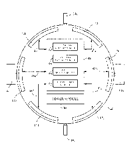
For example,
the terms "component," "module," "system," "apparatus," "interface," or the
like are
generally intended to refer to a computer-related entity, either hardware, a
combination
of hardware and software (firmware), software, or software in execution,
unless the
context clearly indicates otherwise. For example, such a component may be, but
is not
limited to being, a process running on a processor, a processor, an object, an
executable, a
thread of execution, a program, and/or a computer. By way of illustration,
both an
application running on an electronic computing device and the device itself
can be a
component. One or more components may reside within a process and/or thread of
execution and a component may be localized on one computer and/or distributed
between two or more computers.
[0060] Referring in more detail to FIGURE 4, the satellite 10 is depicted in a
view in the x-z plane
in FIGURE 3. It will be appreciated that FIGURE 4, like other depictions used
herein to
describe the subject radio systems and their components, is not to scale, It
depicts the
solar panels 14a and 14c, as shown in FIGURE 3, as well as the diametrically
opposed
companion solar panels 14a' and 14c' mentioned above, It also schematically
depicts a
plurality of antenna modules 12a, 12b, 12c, 12d, 12e, and 12f, representing
all of the
antenna modules onboard the satellite 10, for transmitting and receiving radio
signals as
discussed above in connection with FIGURE 3. This schematic depiction is
intended to
convey the principle of operation of the present embodiment whereby the
plurality of
antenna modules in combination will be capable of transmitting and receiving
radio
= CA 03032969 2019-02-04
WO 2018/039292 PCT/US2017/048110
- 25 -
signals to and from a node in substantially all radial directions. (However,
as already
noted, the system described herein can also be implemented with satellites
having
antenna arrays that transmit with less than full 3600 spherical coverage.)
[0061] The satellite 10 includes a power module 30 capable of providing a
reliable source of
electrical power for operating the components of the satellite. The power
module 30
includes batteries that are charged by the electricity generated by the solar
panels.
Suitable power regulating equipment provides steady-state power to the various
electronic components carried by the satellite even though the solar panels
will spend one
half of each satellite orbit out of sight of the sun. In addition to the power
module the
satellite includes a central processing unit 40 with an operating system
module 42 that
stores operational software for controlling the various functions of the
satellite. As shown
in FIGURE 4, the CPU 40 is operatively connected to all of the antenna modules
12 via
power and data links 40a, 40b, 40c, 40d, 40e, 40f, etc.
[0062] FIGURE 4 also illustrates four main operational modules under the
control of the
operating system module. These components are likewise included in ground-
station
nodes. Each satellite node in a radio route necessarily uses two antenna
modules. Since
the satellites have no preferred orientation, it is necessary for each
satellite (node) to
select antenna modules 12 to communicate with another node, either a satellite
or a
ground station. An antenna pairing module 44 under the control of the
operating system
uses information messages received from other nodes (ground stations or other
satellites) to pair an antenna module in one node for transmitting/receiving
signals with
an antenna module in another node for receiving/transmitting signals. The
radio signals
exchanged between nodes are analyzed by a route creation module 46 that uses
algorithms discussed further below to create a radio route between two ground
stations.
(Ground station nodes have corresponding central processing units.) Once a
radio route
CA 03032969 2019-02-04
WO 2018/039292 PCT/11S2017/048110
- 26 -
has been established, a data movement module 48 within each node controls the
transmission along the radio route of communication signals CS (see FIGURE 1).
As
suggested above, the illustration in FIGURE 4 of separate modules for antenna
pairing and
route creation does not necessarily imply that identifying antenna pairs for
transmitting/receiving signals between nodes and selection of potential radio
links as a
radio route are other than part of a more or less unitary process of creating
a preferred
radio route for transmitting data communications from one ground station to
another.
[0063] III. Creating Radio Routes for Data Communications
[0064] Launching sufficient numbers of the satellites 10 in random or
pseudorandom orbits as
discussed above enables implementation of a variety of route creation
strategies. This
section will discuss two embodiments, and variations thereof, of radio routes
created
using such a satellite system. One embodiment creates a radio route that
comprises radio
links between a single satellite and two ground stations. Another embodiment,
which
allows for communications over longer distances, creates a series of one or
more
subroutes comprising a first ground station, a first satellite and a second
ground station,
and another subroute comprising the second ground station, a second satellite,
and a
third ground station, and if necessary a third subroute comprising the third
ground
station, a third satellite, and a fourth ground station, and so forth. This
radio route would
enable communications between a first ground station and an nth ground station
using n-1
satellites. Variations on these embodiments are discussed below as well. For
example,
those skilled in the art will understand that a radio route can also include
satellite-to-
satellite links if the computers resident in the nodes assemble such a route
based on the
principles discussed below.
[0065] The ability to transmit data between ground stations using radio routes
according to this
embodiment of the present system is essentially confirmed by the known
operational
CA 03032969 2019-02-04
WO 2018/039292 PCT/US2017/048110
- 27 -
capability of the Motorola-Iridium system, which uses fixed satellites with
attitude
control. That type of system was able to establish communication links
directly between
satellites and hand-held units on the ground in spite of the limited antenna
power (or
gain) available in such units. Thus, an embodiment of the present system that
uses
antennas with limited power in the satellites in combination with ground
stations having
more powerful, different type, and/or a greater number of antennas is
virtually assured of
being able to establish radio routes between two ground stations.
[0066] A. Two Ground-Station/One Satellite Radio Route
[0067] A basic embodiment of a satellite mesh system according to the present
invention uses
one of the satellites in accordance with the above description to create a
radio route for
communications between two ground stations. This route involves two radio
links, one
between a first ground node and a satellite node, and the other between that
satellite
node and a second ground node. Although the configuration of a ground station
may be
different from that of the satellites, conceptually the transmission and
reception of radio
signals are processed by each essentially the same way. The creation of radio
routes may
be enhanced by ground station nodes using more and/or more powerful antennas,
as well
as different antenna types, as compared to those carried by the satellites,
since the nodes
on the ground do not have the same constraints on weight, power, and space
limitations
as the satellites. In addition, the ground station antennas can be mounted on
tall buildings,
towers, high hills, etc., to maximize line-of-sight visibility with the
orbiting satellites. In
addition, the ground nodes only transmit throughout a hemisphere, rather than
in all
spherical directions like the satellite nodes, thus reducing the cost of
adding antennas for
enhanced link creation.
- 28 -
[0068] 1. Radio Route Creation and Maintenance
[0069] The principles underlying creation of radio links in the satellite mesh
systems
described herein will first be described by using a paradigm in which all
transceivers, both satellites and ground stations, are considered to be nodes
in
the mesh. This will enable an understanding of how a radio route is created
with
more than one node-to-node link (that is, with at least three nodes). Creation
of
a radio link between satellites or a radio link between a satellite and a
ground
station is in most relevant respects the same. Identifying and optimum radio
links and routes between pairs of nodes is in some ways analogous to the
manner in which routes are created in the ground-based system described in the
inventor's U.S. Patents No. 5,793,842 and No. 6,459,899.
[0070] An important difference, though, is that the present system, unlike
those known
in the prior art, creates routes using nodes the positions and orientations of
some
of which (the satellites) change over time. Accordingly, while prior fixed-
node
systems might occasionally have to change a radio route for reasons discussed
above in connection with FIGURE 1, they did not involve a dynamic
environment with moving and tumbling nodes that required the system to be
capable of automatically and dynamically updating the selection of
transmitting/receiving antenna pairs in the nodes as they move relative to
each
other and change attitude. For example, Motorola-Iridium systems used
satellites with fixed attitudes and known relative positions, thus making
possible
optimum route creation in a manner known for ground-based systems (although
the Motorola-Iridium system is not known to use the nodes themselves to create
radio routes).
[0071] As just indicated, the present system and method for creating a radio
route with
robust radio links between nodes involves selecting pairs of antennas and
estimating the
CA 3032969 2019-03-29
CA 03032969 2019-02-04
WO 2018/039292 PCT/US2017/048110
- 29 -
"quality" of each link by criteria discussed below. An explanatory example
will be
described in connection with FIGURE 5, which shows a plurality of satellites
with address
nos. 140, no. 250, no, 280, no. 300, and no. 165, which can form radio links
with ground
stations with address nos. 1000, no. 1052, no. 1630, and no. 2001. The
following explains
how the just the nodes in the system determine a preferred radio route for
data
communications (calls) from ground node no. 2001 to ground node no. 1000 by
choosing
between two potential routes, one via satellite no. 250 and the other between
satellite no.
300. In a typical system there will be about 200 satellites. The number of
ground stations
can vary, of course, but FIGURE 5 illustrates a few such ground stations over
a wide area
about, say, 700 miles in diameter.
(0072) The link selection process is begun by transmitting from each ground
node a routing
signal in the form of an initial information signal comprising an identifying
packet with
the initial information. The antenna modules in every node, both satellite
nodes and
ground nodes, are each given an identifying number. In addition, each node is
identified as
either a ground node, sometimes referred to as type A, or a satellite node,
sometimes
referred to as type B, This node identifying data will typically be contained
in a packet
header, and the identifying packet will include a payload comprising an
initial sample data
stream. The following Table 1 is an example of digital first information
signals transmitted
from two of the antenna modules in a first sending ground node, say the node
assigned
address "1000."
TABLE 1
Packet No. 1
Node address no. 1000
Node type: A
Node antenna no. GA1
Link count: 1
Sample data (payload) XX = . XX
CA 03032969 2019-02-04
=
WO 2018/039292 PCT/US2017/048110
- 30 -
Packet No. 2
Node address no. 1000
Node type: A
Node antenna no. GA4
Link count: 1
Sample data (payload) XX ... XX
Similar packets will be transmitted continuously from all of the antennas in
all of the
ground nodes. These signals will be received by a number of other nodes, both
ground
stations and satellites, but the antenna pairing modules in the nodes will
reject
information signals sent from the same node type. The satellites also store
the number of
links back to the sending ground node. In this case, the link count is one,
[0073] The initial sample data stream will typically be a known sequence of
bits used to evaluate
the quality of a potential radio link between two nodes in a manner described
just below.
It is anticipated that the antennas in each node can transmit the information
signals at
random intervals without encountering interference with information signals
transmitted
from other nodes. This is because the number of nodes, and the number of
antennas in a
given node, that will receive signals from other nodes will likely be small.
Alternatively,
the antenna modules in the nodes can transmit information signals in
preassigned time
slots to minimize even further the possibility that an information signal
transmitted from
one node will arrive at a given antenna in another node at precisely the same
time that the
given antenna is transmitting its information signal.
[0074] Continuing with this example, the second step in the process involves
an evaluation by all
of the satellite nodes that receive initial information signals from the
ground nodes. The
process involves a plurality of operations carried out in the satellite
antenna pairing and
route creation modules. The antenna pairing modules in the receiving
satellites store the
antenna on which it received the initial information signal. In the FIGURE 5
example,
satellite no. 250 stores satellite antenna SA6 associated with ground node
address no.
1000, and satellite no, 300 stores satellite antenna no. SA3 associated with
ground node
CA 03032969 2019-02-04
WO 2018/039292 PCT/US2017/048110
- 31 -
address no. 1000. The route creation circuitry determines a figure of merit of
the
received initial information signal that reflects a quality of the signal
transmitted over that
pair of antennas in the respective ground station and satellite. The figure of
merit results
from an analysis of certain parameters according to algorithms in the nodes,
its purpose
being to assign a quantitative value for ranking the suitability of particular
antennas in the
two nodes as a radio link in the radio route to be created between an
originating ground
station and a destination ground station. That is, this step in the process
involves ranking
the quality of a potential radio link between a ground station sending an
initial
information signal and a satellite receiving it. Examples of properties of
received signals
that can be used to derive a figure of merit (signal quality) are one or more
of signal
strength, the error rate in the data stream, and signal-to-noise ratio. In
this example, the
figure of merit ranges from one (worst quality) to 10 (best quality).
[0075] The next step is for the route creation circuitry in all of the
satellites to send routing
signals in the form of linking information signals from all of their antennas.
To illustrate,
assume that satellite with address no. 250 receives an initial information
signal from
sending ground node no, 1000. Table 2 shows the linking information sent in
packet form
from every antenna in node no. 250 vis-a-vis a potential link with sending
ground node
no. 1000:
TABLE 2
Transmitting from: Node No. 250
Node type:
Node transmitting antenna no. SA1
Node receiving antenna no. SA6
Linking node address no. 1000
Linking node antenna no. GA1
Link count: 2
Link figure of merit (FOM) 6 of 10
Sample data (payload) XX ... XX
Table 3 shows the linking information sent in packet form from every antenna
in node no.
300 vis-à-vis a potential link with sending ground node no, 1000:
CA 03032969 2019-02-04
WO 2018/039292 PCT/US2017/048110
- 32 -
TABLE 3
Transmitting from: Node No. 300
Node type:
Node transmitting antenna no. SA4
Node receiving antenna no. SA3
Linking node address no. 1000
Linking node antenna no. GA10
Link count: 2
Link figure of merit (FOM) 3 of 10
Sample data (payload) XX ... XX
The linking signals will not be accepted at other satellites, which are the
same type (type
B) as the satellites no. 250 and no, 300 sending the linking message. In
addition, the
ground nodes will be programmed likewise to reject linking signals with a
linking node
address the same as the receiving ground station. Note also that the link
count from
Table 1 is incremented by one by the satellites, reflecting the number of
links (two) to the
sending ground node no. 1000.
[0076] The antenna pairing circuitry in a receiving ground station that
receives a linking signal
stores at least the satellite node addresses from which the linking signals
were
transmitted, as well as the antenna on which the linking signals were received
at the
receiving ground node. In FIGURE 5, the ground station no. 2001 stores
satellite address
no, 250 associated with antenna no. GAS, and satellite address no. 300
associated with
antenna no. GA21. The receiving ground node also determines respective figures
of merit
for potential links between itself and satellite no. 250 and between itself
and satellite no,
300. In this example, the FOM = 6 for a potential link between ground station
No. 2001
and satellite no, 250 and FOM = 8 for a potential link between ground station
No. 2001
and satellite no. 300.
[0077] A preferred radio route between from the receiving ground station to
the sending ground
station is then determined based on the figures of merit of the available
potential links. In
the example shown in FIGURE 5, the total figure of merit for the radio route
via satellite
no. 250 is 12 (6 + 6) and the total figure of merit for the radio route via
satellite no. 300 is
CA 03032969 2019-02-04
WO 2018/039292 PCT/US2017/048110
- 33 -
11 (3 + 8), Therefore, the preferred radio route is via satellite no. 250.
Note that it is the
quality of the overall route that determines the choice, not the quality of an
individual
link. As described in more detail below, a data transmission destined for the
sending
ground station no. 1000 includes the destination address (node no. 1000). The
receiving
ground station no. 2001 knows that the first radio link in the route to
destination node no.
1000 is satellite no. 250 and that a transmission on antenna no. GA5 of ground
station no.
2001 will be received at satellite no. 250, (Optionally, the satellite no. 250
can confirm
that the transmission is from ground node no. 2001 if the transmission is
received on
satellite antenna no. SA1.) Satellite no. 250 has stored antenna no. SA6 as
the antenna to
use for data transmissions to ground station no. 1000. (Optionally, the ground
station no.
1000 can confirm that the transmission is from satellite no. 250 if the
transmission is
received on ground station antenna no, GA1.) Thus, the selected antennas at
the ground
stations and the satellite (the nodes) direct transmission signals from an
originating node
to a satellite and then to a destination node without requiring that the
entire route being
stored at any one node or central location and without requiring a central
computer to
determine a preferred route. From this example, one skilled in the art will
understand
how radio routes are constructed for data communications from any of multiple
receiving
(destination) ground stations to any of multiple sending (originating) ground
stations.
[0078] It will also be understood that the satellites no. 140, no. 280, no.
165, etc., may also receive
initial information signals from the ground station no. 1000 and send linking
signals that
are received by ground stations no. 1052, no, 1052, no. 1630, and no. 2001.
Likewise, all
of the satellites shown in FIGURE 5 and any others within radio range (see
FIGURE 2) may
receive initial information signals from all of the ground stations no, 1052,
no. 1630, and
no. 2001, and any others within radio range. However, the determination of a
preferred
route between any two ground stations proceeds according to the above
discussion, in
CA 03032969 2019-02-04
WO 2018/039292 PCT/US2017/048110
- 34 -
which the combined figure of merit of both potential links in a radio route
between the
ground stations is evaluated by the receiving ground node of a potential radio
routes.
[0079] The above steps are continuously repeated at predetermined intervals,
including during
the transmission of packets of communication signals over a radio route. Thus,
as the
satellites move and change orientation, the modules in the nodes can
continuously update
the evaluation of the radio links between nodes, and can change the preferred
radio route
between originating and destination nodes. This is facilitated by the fact
that each node
actually only communicates with a limited number of other nodes and thus only
a limited
number of links has to be updated with each iteration of the link creation
process. The
frequency of the link refreshing process will depend on various factors, but
it is believed
that frequencies between 0.5 and 20 Hz will be adequate in a typical system.
As already
noted, the link selection and maintenance procedure is performed by
computations solely
using the onboard calculating capacity of the nodes as described herein.
[0080] It should be also noted that one node might receive a signal from
another node on more
than one antenna, depending on the properties of the antenna modules, such as
their
HPBW. However, the route creation process is the same as described above in
that
instance. It will also be appreciated that many different criteria can be used
to evaluate
the quality of the potential link between the nodes. Typical ones would be
direct
indications of link quality such as the strength of the received signal and
the error rate
estimate. However, other criteria can be used as well. For example, the amount
of
remaining battery life in each of the nodes in the potential link could be
determined and
the quality rating (figure of merit) adjusted to account for how long a
satellite has been
exposed to the sun as an indication that battery power might only remain
strong enough
to support a link for a short time. Another criterion could be link loading,
which refers to
the number of potential radio links with other nodes that is stored at a
particular node.
CA 03032969 2019-02-04
WO 2018/039292 PCT/US2017/048110
- 35 -
Each node in the system (ground stations and satellites) can eliminate
potential links with
a quality below a predetermined threshold (say FOM = 2). This will prevent a
route from
being formed using one very high quality link and one very low quality link,
the latter of
which may disrupt data communications even though the overall quality of the
route
appears to be satisfactory. It may also reduce the time required to determine
a preferred a
radio route by eliminating a number of transmissions between the nodes.
[0081] 2. Transmitting Data Communications over the Radio Route
[0082] As just explained, once a plurality of links is assembled into a radio
route, it can be used to
transmit communication signals from an originating node to a destination node.
However,
one issue that must be addressed when communicating data transmissions over
the radio
route is that a single antenna in a node cannot both transmit and receive
signals
simultaneously. This issue is addressed in a variety of ways in the '842 and
'899 patents.
One that is particularly adapted to the present system is the designation of
the nodes as
one of two types, called "A" and "B" in this description (or "odd" and "even"
in the '842
and '899 patents). In such an arrangement signals transmitted from one type of
node are
separated in some fashion from signals transmitted from the other type of node
so that a
node can receive signals on the same antenna that it uses for transmitting
signals.
[0083[ One way of doing this is for one type of node to transmit in certain
frequency bands and
the other type to transmit in different frequency bands. In this arrangement
an antenna in
a node can transmit and receive signals at the same time. One drawback is the
necessity of
providing sufficient separation between the respective frequency bands to
ensure that the
there is no interference when an antenna is transmitting and receiving at the
same time.
Another way of separating signal transmission and reception is to transmit
from one type
of node in a particular time slot and from the other type of node in a
different time slot
interleaved with the first time slot.
CA 03032969 2019-02-04
WO 2018/039292 PCT/US2017/048110
- 36 -
[0084] Data/communication signal transmission in accordance with this
description is controlled
by the data movement modules 48 in the satellites 10. For example, a data
communication
comprising packets of data with a header and a payload will be received at an
originating
ground station. The header will typically include address information,
including
identification of the destination ground station. The data transmission module
unpacks
the address information and indicates the system address (node number) of the
destination node. The packets will then be sent to the destination ground
station over the
radio route established in the manner described above. An important aspect of
the
present system is that the preferred radio routes are subject to change even
during an
ongoing data transmission. However, the data packets arriving at the
destination ground
station can be unpacked, undergo error correction, and be reassembled in the
proper
order in accordance with known principles, even if the packets arrive out of
order
because they traveled via different routes or were delayed while a different
route was
being created.
[0085] 3. Summary
[0086] It will be apparent to those skilled in the art that the present system
is not simply a
superposition of the route creation techniques described in the '842 and '899
patents on a
three-dimensional mesh in which the nodes include satellites instead of fixed
devices in
an essentially two-dimensional space. There are numerous factors that go into
link
selection and route creation, some of which are discussed above, that must be
accounted
for in the type of space-based, three-dimensional mesh described herein. For
example,
since the satellites have different trajectories, some of which will pass over
large expanses
of unpopulated oceans, while others will pass over land masses that will
generate more
data transmissions, battery life can vary greatly from satellite to satellite.
Accordingly, the
CA 03032969 2019-02-04
1
WO 2018/039292 PCT/US2017/048110
- 37 -
amount battery charge remaining can be an important parameter in selecting a
satellite as
a node in a radio route.
[0087] The use of a single satellite to establish an optimum or preferred
radio route has several
advantages. One is that it identifies a preferred route virtually
instantaneously because
the radio signals passed between the satellites and the ground stations
include
information that is used by algorithms stored at the ground stations and in
the satellites
to calculate a preferred radio route in small fractions of a second. Thus, as
soon as a
ground station transmits a signal indicating that a route is needed to another
ground
station, the route can be established immediately and used for transmitting
communication signals. This type of three-node route can "refresh"
sufficiently rapidly to
minimize disruptions of data transmissions so that if at a later time a
different satellite, or
different antennas on the same satellite, would provide a better quality
route, the route
configuration can be adjusted nearly instantaneously to provide better quality
links and
minimize delays in data transmission. It also allows for changing the
satellite used in the
route for other reasons, an example being waning battery life.
[0088] Those skilled in the art will understand that engineering a system in
accordance with the
above description will require trade-offs among different aspects of the
system. Thus, an
actual system will likely involve many competing considerations in optimizing
a
particular design. Some of these considerations are the number of satellites,
satellite
altitude, the number of antennas, particularly in the satellites, the beam
width of the
antennas, the size of the satellites, the cycle time for updating route
creation, just to name
a few.
CA 03032969 2019-02-04
WO 2018/039292 PCT/US2017/048110
- 38 -
[0089] B. Examples of Radio Routes Created Using the Present System
[0090] An aspect of the present embodiment is that the probability of there
being at least one
satellite present to establish a ground-to-satellite-to-ground radio route can
be readily
increased by simply placing more satellites in orbit, in accordance with the
description
above. Since the satellites are very light and inexpensive, increasing their
number is an
economically feasible way of increasing the reliability of the system.
Although there may
be periods when there is no satellite immediately available for the
establishment of a
radio route between two ground stations, the rapid rate at which the system
can refresh
itself increases the probability that at least one satellite will soon (likely
within a few
seconds) become available. In most applications, a time lag with a duration of
this order of
magnitude will be acceptable. For those reasons, a particularly useful
application of the
present embodiment is providing reliable radio routes over particular
geographic areas.
[00911 1. Establishing a Single-Satellite Route in a Particular Geographic
Area
[0092] FIGURE 6 illustrates an application of this aspect of the invention in
which the plurality of
randomly orbiting satellites is used to create a ground-to-single-satellite
radio route over
which signals can be transmitted and received only over a predetermined
geographical
area. The example presented here is a system for transmitting and receiving
communication signals throughout the country of Egypt. FIGURE 6 is a map of
Egypt that
shows a coverage area CA in which a single satellite is used to effect
communications
between Cairo and the southwest corner SW of the country. As above, the system
includes
200 satellites. The circle segment labeled CO indicates an area in which a
satellite will see
Cairo. The circle segment labeled SW indicates the area in which a satellite
will see the
southwestern corner SW of the country. The area CA represents the overlap of
these
circles, signifying the area where both Cairo and the southwest corner SW will
see the
same satellite.
CA 03032969 2019-02-04
WO 2018/039292 PCT/US2017/048110
- 39 -
[0093] The area CA of the overlapping circles CO and SW is given by the
following relation:
1
CA ------ 2DH' cos' (D11¨m ¨ ¨m (4DH2 ¨ m2)"2-
2 2
where m = 700 miles, which is the distance between Cairo and SW, and DH is the
distance
to the horizon from a satellite (see FIGURE 2). Accordingly, the area CA in
which a single
satellite will enable communication between ground stations at Cairo and the
southwest
corner SW is about 9,800,000 sq. mi. By the calculation above in connection
with FIGURE
2, the coverage area CA is about 5.0% of the earth's surface. If there are 200
satellites in
random orbits per the present description, there will be on average at least
10 satellites
visible from any point within the coverage area. Stated another way, the
probability that
at least one satellite will not be available for communication between Cairo
and SW is
only 0.95200 0.0035% (or about 35 in a million). In an actual implementation
the area
will be somewhat less because the closer a satellite is to the horizon for a
particular
location, the less likely it is to be able to receive radio signals from a
ground station at that
location due to atmospheric effects or interference from nearby buildings or
topographical features such as mountains or the like. The ability of a ground
station to see
satellites near the horizon can be improved by placement of the ground nodes
on high
towers or hills or tall buildings. Since ground stations will typically use
utility power,
there is normally little or no constraint on the power available at ground
stations. In
addition, the ground stations can utilize antenna designs that increase
weight, while in the
satellites the goal is generally to reduce weight to minimize launch costs. In
other words,
the engineer designing the system would have much more flexibility in
configuring the
ground stations to increase their effective range and thus make more
satellites available
for single-satellite route creation than might otherwise be available if the
ground stations
had the same antenna modules in the same numbers as the satellites.
-40 -
[0094] FIGURE 6 uses the dotted circle segments to indicate the coverage area
for
communications with other ground stations, such as the northwest corner
NW and southeast corner SE of the country. For example, a satellite would
have to occupy the overlap between the two circles labeled NW and SE for
communications between ground stations at those locations. Stated another
way, any single satellite within that area would support a radio route
between those ground stations. As another example, any satellite within the
overlapping area of two 2000-mile radius circles centered on Cairo and SE
would support a radio route between ground stations at those two
locations. The same principle applies to communications between two
ground stations located at Cairo and NW, and so forth.
[0095] A radio route is established between two ground stations (say at Cairo
and
near SW) in the manner described above for establishing radio links
between nodes. While in the present embodiment a given radio route will
only include a single satellite because all satellites are nodes of one type
and
all ground stations are nodes of a different type, the route need not
necessarily comprise only a single satellite. Nevertheless, it is expected the
route creating modules in the nodes will inherently favor single-satellite
radio routes because they will likely provide a preferred route in terms of
the collective figures of merit of the links in such a route. In addition, a
radio route is maintained system between the two ground stations even if
the satellite originally used to create the route disappears over the horizon
and from the view of one of the two ground stations (see FIGURES 1 and 2).
In that case, the computers aboard a different satellite in view of both
ground stations can be used to create a new radio route. During the brief
times that could theoretically occur when no route is available, the
transmission data is stored in a buffer memory until a route is available. As
noted above, the communication data packet headers include sequence
information that permit them to be reassembled in order at the
CA 3032969 2020-03-09
CA 03032969 2019-02-04
WO 2018/039292 PCT/US2017/048110
- 41 -
destination node for transmission to a user connected to the destination node
via a
landline or WiFi.
[0096] 2. Single-Satellite Routes With Wide Area Coverage
[0097] FIGURE 7 plots the general relationship between the distance separating
two ground
stations and the area in which two circles centered on respective stations
overlap with
each other. If the two points are about 700 miles apart (as in the example
above using
Egypt), the overlapping area CA of two circles with a diameter of 2000
miles is about
78% of the area AR (FIGURE 2). As the distance increases, the overlapping area
correspondingly decreases, FIGURE 7 shows the overlapping area LA of two
circles
centered on New York and Los Angeles. That area is about 3,400,000 sq. mi.,
which is only
27% of the area AR covered by a single satellite. This represents only 1.7% of
the earth's
surface of 197,000,000 sq. mi. For a system comprising 200 satellites, there
only will be
about 3 or 4 satellites visible from both cities. Considering that the Rocky
Mountains will
intercept westward signals toward Los Angeles at shallow angles to the earth's
surface,
there may in fact be no satellite capable of communicating with both cities
for long
periods of time. Russia presents an even more extreme situation. The distance
between
Vladivostok and St. Petersburg is about 4000 miles, meaning that in no case
will a single
satellite be capable of providing a radio route between them. Even cities
closer together in
Russia may not present a sufficiently large probability of establishing a
single-satellite
radio route between them if they are on opposite sides of the Ural Mountains.
[0098] The single satellite embodiment of the invention is readily adapted to
settings where
ground nodes are too far apart, or where topographical features will severely
limit the
number of satellites visible to both ground nodes. In that case one or more
intermediate
ground nodes are provided between the distant locations. The intermediate
ground
stations will appear to the system just like the satellite nodes. To
illustrate the point,
CA 03032969 2019-02-04
WO 2018/039292 PCT/US2017/048110
- 42 -
consider a system in which ground nodes are located at New York, Kansas City,
and Los
Angeles. The route creation algorithms in the satellites visible to the New
York/Kansas
City ground nodes will determine a first preferred radio route segment and
those in the
satellites visible to Kansas City/Los Angeles ground nodes will determine a
second
preferred radio route segment in series with the first. Although the route
will not
necessarily be constrained to comprise two single satellite route segments
(New York/Kansas City and Kansas City/Los Angeles), it is believed that will
typically be
the end result. The link count discussed above could be used as a factor in
selecting the
preferred radio route between two distant ground stations, which in some
circumstances
could result in a single satellite radio route.
[0099] However, the system will be free, as discussed, to create a route, say,
between New York
and Los Angeles using a single satellite, or an intermediate
satellite/satellite link if the
route creation computers in the nodes so dictates. Satellite-to-satellite
links can be
established if a sufficient number of satellites of the same "type" as the
ground stations
are placed into orbit. These satellites would function as a kind of blind node
that could
only be used for communications between satellites of the other type but not
with ground
stations. It is expected that a limited number of such blind node satellites
would be
required because of the great distances over which orbiting satellites would
able to see
each other.
[01001 3. Additional Properties of Single Satellite Radio Routes
[0101] One property of the mesh system described herein is the ability to
restrict data
communications to particular ground stations, For example, if security
concerns required
that certain communications from a ground station only be capable of
transmission to one
or more other ground stations, the packet header could include encrypted
information
that could only be decoded by a ground station with a suitable decryption key.
The
CA 03032969 2019-02-04
WO 2018/039292 PCT/US2017/048110
- 43 -
communication could be double encrypted by including an encryption key in the
information signals used to create radio links as well as in the data
communications
themselves. The same principle could be used to prevent communications to
certain
ground stations in general. For example, in the example above relating to a
system
deployed for communication between ground stations in Egypt, data packets sent
from a
ground station could include an address field permitting the creation of radio
routes only
with other ground stations in Egypt. This type of single or double encryption
could also be
employed by a country for political or religious reasons.
[0102] IV. Rotating Satellites
[0103] As already discussed, designing a satellite-based radio mesh system in
accordance with
the above description involves myriad trade-offs among a wide variety of
parameters.
Two particular parameters that work at cross purposes, and thus require
judicious
selection, are the beam widths of routing signals and calls transmitted by the
antennas in
the nodes and the power (gain) of the antennas. On the one hand, greater beam
width will
increase the probability that a beam match can be created, but a greater beam
width
reduces the gain of the antenna. Conversely, a narrower beam will increase
antenna gain,
but reduce the probability of creating a beam match between nodes. This trade-
off is
particularly significant in the satellite nodes because the satellite antenna
configuration
has to take into consideration constraints on the weight and size of the
satellites, which
limits the number of antennas the satellite can carry, and on the electrical
power available
from onboard batteries. it is also desirable to increase the number of
possible beam
matches between nodes because some radio beams may be weakened by grazing the
earth's surface, which can partially block the signal before it reaches a
receiving node.
[0104] Achieving the proper trade-off between beam width and antenna gain is
important to the
efficient functioning of a random-orbit satellite system. Such a system relies
on the
CA 03032969 2019-02-04
W02018/039292 PCT/US2017/048110
- 44 -
statistical probability that routes can be created using randomly orbiting
satellites to
create and select routes. A basic system that is simple and inexpensive to
implement, and
is especially effective in creating single satellite radio routes, uses
tumbling satellites as
discussed above. As already described, the satellites' antennas point out into
space¨
towards each other and the earth¨to enable the establishment of links between
nodes. A
fundamental property of the system is its dependence on routing signals and
data
transmissions of sufficient strength reaching other nodes (ground stations and
satellites).
The system relies on having enough satellites in orbit and making the proper
design
trade-offs, including beam width vs. gain, to enhance the probability that a
suitable route
can be created between two ground stations via one or more satellites.
However, there
may be system installations in which better data transmission could be
achieved by a
multiple satellite route if the probability of creating high quality (figure
of merit) links
between satellites is increased.
[0105] The present embodiment utilizes satellites that rotate about an axis,
which, as explained
herein, increases the likelihood that a route with high quality links and sub
routes can be
created using one or more satellites. As explained below, employing rotating
satellites
enables beam width to be reduced, with a corresponding increase in gain,
thereby
resulting in higher quality radio links between nodes.
[0106] A. Principles Underlying the Present Embodiment
[0107] In the tumbling satellite embodiment discussed above, an exemplary
satellite
configuration uses 25 antennas covering about 60% of the surface of a
spherical satellite.
Thus, a rough estimate of the probability of a radio beam transmitted by such
a satellite
being received by another like satellite would be about 36% (0.6 x 0.6). It
will be
appreciated by those skilled in the art that this is only an estimate, since
the radio beams
will have side lobes that will increase the probability that a link will be
created to a
CA 03032969 2019-02-04
WO 2018/039292 PCT/US2017/048110
- 45 -
certain extent. If the diameter of the satellite is doubled, the diameter d of
the parabolic
dish antennas used in the above-described example can also be doubled. By
above
equation (1), a = (k xy)/d, the HPBW will be halved, to 700, from the value of
the antenna
example given above. While the area of the beam will be only 1/4 as large, the
antenna gain
will be increased by a factor of four, or about 6cIB. On the other hand, the
probability of a
radio beam transmitted from one tumbling satellite being received by another
is reduced
to about 2% (36% x (Y4)2).
[0108] As discussed above in the tumbling satellite embodiment, repeated radio
signals sent by
nodes in the system include information on links and sub routes that need only
include
the address of a final ground destination and a figure of merit to that
destination, The
rotating satellite embodiment takes the tumbling satellite embodiment as a
point a
departure toward a technique for increasing the likelihood of creating a radio
link,
especially between satellites with high-gain, narrow-beam antennas. It will be
appreciated, particularly from the discussion that follows, that a particular
radio route in
a spinning satellite system may not last as long as in a tumbling satellite
system.
Accordingly, one way to enhance the route creation process would be to use
route
creating signals that have a smaller amount of sample digital data (see Tables
1-3, above)
to enable them to be transmitted in a shorter period of time to effect more
rapid route
creation.
[0109] As also discussed above, data transmissions ("calls") will typically be
in the form of
packets with a header, which includes address data indicating the packet
destination, and
a payload comprising the content of the transmission. Header information in
multiple
packets can be used to arrange the packets in the same order in which they
were
transmitted. Although a particular radio route in a rotating satellite system
may not last
as long as in a tumbling satellite system, the data transmission packet
headers will include
CA 03032969 2019-02-04
W02018/039292 PCT/US2017/048110
- 46 -
information on the proper order of the packets for use by the destination
ground station
to reassemble the transmission. Thus, while there may be delays in completing
a
particular data transmission while a new radio route is created in mid-
transmission, that
potential drawback will be offset by the fact that the higher gain radio beams
made
feasible by using rotating satellites will be more likely to establish radio
routes by which
data transmissions between certain ground stations can be made in the first
place.
101101 B. Linking Satellites to Satellites
[0111] The discussion further above of the tumbling satellite embodiment
points out that the
establishment of radio links between ground stations and satellites can be
enhanced by
increasing the number and gain of ground station antennas. This is feasible in
most
installations because ground stations typically do not have the constraints on
weight,
available space, and electrical power that exist with the satellites. In the
present
embodiment the establishment of radio links by beam matching between
satellites is
enhanced by using satellites that are deployed into orbit deliberately
spinning about a
rotational axis. In one embodiment, the satellites themselves have the same
components
as the satellite depicted in FIGURES 3 and 4 and described in the text above
associated
with them.
[0112] The angular velocity of the satellites will be relatively high. For
purposes of illustrating
the operation of a typical system using rotating satellites, it will be
assumed that the
satellites are deployed with an angular velocity co 2n cad/sec (60 rpm). Those
skilled in
the art will understand that this example is not meant to be limiting and that
it is within
the scope of this disclosure to employ any angular velocity effective to
establish radio
routes as described and claimed herein. The orientation of the axis of
rotation will not be
controlled, but principles of physics dictate that each satellite will assume
an axis of
rotation through its center of mass and the axis of rotation will precess
around the
CA 03032969 2019-02-04
W02()18/039292 PCT/IJS2017/048110
- 47 -
angular velocity co. However, the orientation of the axis of rotation at any
given time does
not affect the creation of radio links, as will be apparent from the
discussion that follows.
[0113] Rotating satellites increase the probability of a transmitted radio
beam being received by
another satellite because the satellite antennas "sweep" an area as the
satellite rotates.
This can be understood by considering the satellite S1 shown in FIGURE 8A,
which is
schematic cross-section through the satellite "equator," corresponding to the
equator 16
of the satellite 10 in FIGURE 3. In this example, the satellite Si comprises
five antennas
121, 122,123, 124, and 125, each having an HPBW of 70 , arranged equally
around its
equator 16 and rotating about the z-axis at an angular velocity co. A location
RL remote
from the satellite and lying in the plane of the equator will "see" five
antennas as the
satellite rotates through one complete revolution. It will be understood that
this number
will be different for locations not in the equatorial plane, but the principle
still holds. It
will also be appreciated that the number may increase or decrease because of
precession
about the rotational axis, but most locations remote from the satellite
(including ground
stations) will still see plural antennas as the satellite rotates. Thus, a
second satellite with
its equatorial plane in the equatorial plane of the first satellite Si, the
probability of being
able to create a radio link with a 6 dB gain increase over the tumbling
satellite example
above is about 10% (5 antennas x 2% for each antenna). The probability of
creating a
beam match with a ground station antenna is likewise increased.
[0114] It will be understood that this is a highly idealized representation,
which ignores factors
such as precession of the satellites around their axes of rotation, but it
nevertheless
illustrates the concept that rotating satellites present an increased
probability for the
creation of beam matches between two satellites. Nevertheless, considering the
large
number of randomly orbiting satellites available for route creation, the
increased
probability of beam matches using rotating satellites will in many, if not
most, cases be
CA 03032969 2019-02-04
WO 2018/039292 PCT/US2017/048110
- 48 -
sufficient to enable assembly of a radio route with higher quality links
between two
ground stations via multiple satellites. While this will have special
applicability in
reaching ground stations separated by large distances, it also can increase
the reliability
of radio routes between ground stations in other settings.
[0115] 1. .. Counter-Rotating Satellites
[0116] The satellites are preferably deployed with about half of them rotating
in a first direction
about their rotational axis and the other half rotating in the opposite
direction. FIGURE
813, which uses like numerals for like parts in FIGURE 8A, illustrates this
principle by
showing the satellite S1 rotating at an angular velocity o) in a first
direction and a second
satellite S2 rotating at the same angular velocity ¨03 (in the opposite
rotational direction).
This illustrates how a beam match between antenna 12s in satellite S1 and
antenna 124 in
satellite S2 will be sustained longer than if the two satellites were rotating
in the same
direction. That is, if the satellites are rotating in opposite directions,
facing antennas on
the satellites are traveling at essentially the same linear velocity relative
to each other. On
the other hand, if the satellites are rotating in the same direction, their
relative linear
velocity is twice the linear velocity of each. With a sufficient number of
satellites in orbit
(200 in the previous embodiment), it is believed that there is a significant
probability of
having a plurality of counter-rotating satellites over any given geographic
area for which a
radio route is being established, such as the area CA in FIGURE 6. Thus, the
likelihood of
quickly establishing a relatively long-lasting radio route is increased by
deploying at least
some, and preferably about one-half, of the satellites rotating in the
opposite direction
from the others. In addition, not only are two antennas on respective
satellites in
alignment longer, but as soon as they rotate out of view of each other, two
other antennas
of the satellites may align, thus enabling rapid refreshing of the radio link
between the
CA 03032969 2019-02-04
WO 2018/039292 PCT/US2017/048110
- 49 -
satellites. In the example illustrated in FIGURE 813, antenna 121 in satellite
S1 and antenna
125 in satellite S2 will align next.
[01171 Like the example used to illustrate the increased efficacy of using
rotating satellites
discussed just above, this is also an idealized description of how counter-
rotating
satellites can create longer lasting radio links between them. In addition, to
the
assumptions underlying the above description, there may not be at any given
time two
counter-rotating satellites over an area where a radio route is desired
between two
ground stations. Nevertheless, taken together, these examples illustrate the
point that
rotating satellites, and particularly counter-rotating satellites, will
provide a sufficient
probability of establishing a relatively high gain radio link between the
random orbit
satellites to enable reliable data communications between two ground stations
via one or
more satellites. And because the antennas point in a plurality of directions
(preferably
over the entire spherical space surrounding the satellite), the opportunity
for establishing
a radio link between two spinning satellites will in most instances be
enhanced by using
rotating satellites.
[01181 2. Satellites with Different Angular Velocities
[01191 A variation of the embodiment described just above employs satellites
that rotate at
different angular velocities. This variation is depicted schematically in
FIGURE 8C, in
which the satellite SI rotates at an angular velocity col and Sz rotates at a
different angular
velocity 002, The advantage of this system is that the antennas on the counter-
rotating
satellites may be out of phase in the sense that antenna on one satellite may
be pointing
directly to a space between antennas on a second satellite, as depicted in
FIGURE 8C. If
the satellites are rotating at the same angular velocity, this situation can
persist for an
extended period of time, thus weakening a radio link between the satellites,
or perhaps
preventing the establishment of a link altogether. Rotating the satellites at
different
CA 03032969 2019-02-04
WO 2018/039292 PCT/US2017/048110
- 50 -
angular velocities will increase the likelihood that at some angular position
antennas on
both satellites will face each other (be in phase), thus enabling the
establishment of a
useful radio link between them. For example, in the case illustrated in FIGURE
8C, the
antennas on the satellites are exactly 180' out of phase, in that the antenna
12z on
satellite S1 is pointing directly at the space between the antennas 12.4. and
125 on satellite
S2. If col = 1,33 x (oz, the antenna 125 on satellite S2 and the antenna 125
on satellite Sz will
line up as the satellites rotate.
[0120] It is anticipated that certain installations of the system will
utilize numerous satellite to
satellite links, while at the same time being able to tolerate some delays
transmitting calls
between ground stations. This type of installation can benefit from using
satellites that
rotate at slightly different angular velocities. In other words, the system
would be
designed to increase the probability that a satellite transmitting a radio
signal would
rotate at a different angular velocity than a satellite receiving the signal.
The data
communications might be delayed while the radio route is intermittently
disrupted and
refreshed as different antennas on the two satellites disalign and realign.
However, this
can be compensated for by buffering the data communications and sending them
each
interval when the radio link is present.
[0121] In an exemplary approach, the cohort of satellites could be divided
into five groups with
different angular velocities in accordance with the following table.
TABLE 4
Very slow spinner: 0.68 revolutions per second
Slow spinner: 0.84 revolutions per second
Average spinner: 1.0 revolution per second
Fast spinner: 1.16 revolutions per second
Very fast spinner: 1.32 revolutions per second
The discussion immediately above explains how this can tend to increase the
probability
of establishing beam matches between the antennas on respective satellites.
That is, the
CA 03032969 2019-02-04
=
WO 2018/039292 PCT/US2017/048110
- 51 -
above discussion demonstrated one instance of how a satellite rotating at an
angular
velocity 1.33 times the angular velocity of another can facilitate a beam
match. The same
principle applies for other multiples of angular velocity.
[0122] By the same token, this system implementation will also make more beam
matches
possible in a given time period because the antennas on one satellite will
have more
opportunities to line up sufficiently with antennas on another satellite to
form beam
matches if the satellites are counter-rotating at different angular
velocities, There may be
no beam matches between two satellites at a given time, or for a certain
interval, as they
rotate. However, as they continue to rotate at different angular velocities,
antennas on the
satellites will likely form beam matches because antennas on the respective
satellites will
be likely to line up at some point. This may take plural revolutions of the
satellites, but
rotation at different angular velocities greatly increases the probability
that many more
matches will be created as the satellites continue to rotate. It will thus be
appreciated
from the complex interrelationship of the antennas on different satellites as
the satellites
move in their orbits and rotate about their axes that providing plural cohorts
of satellites
rotating at respective different angular velocities will increase the probably
of creating
more beam matches between pairs of the satellites during any given time
interval. Any
resulting delays while beam matches are created may be tolerable if the
alternative is an
inability of a particular ground station to send and receive data
transmissions at all.
[0123] 3. Other Considerations
[0124] It is known that the angular velocity of a body rotating in earth
orbit, especially at lower
altitudes, is subject to decay from a number of factors. For example, even
though the
earth's atmosphere is extremely thin at low- and medium-earth orbital
altitudes, the
region in which satellites used in the present system will preferably occupy,
orbiting
objects nevertheless still experience aerodynamic drag. Forces generated by
the passage
CA 03032969 2019-02-04
WO 2018/039292 PCT/US2017/048110
- 52 -
through the earth's magnetic field of ferromagnetic materials in the object
can also affect
the angular velocity of a rotating body such as a satellite. The tendency of
the rotating
satellites to undergo a reduction in angular velocity over time can be
compensated for in a
variety of ways. One is to use retro rockets or active mechanical devices
known in the
prior art. However, since one of the objects of the invention is to minimize
the cost of
building, deploying, and maintaining the satellites used in the radio systems
described
herein, it is preferred to use passive means for compensating for external
forces on the
satellites or for creating forces to control satellite movements.
[0125] One such means uses solar panels with solar cells only on one side to
utilize the
momentum of photons striking the panels to create a torque about the
rotational axis of
the satellite. For example, referring to FIGURES 3 and 4, for a satellite that
is deployed to
rotate counterclockwise about the z-axis (as viewed in the negative-z
direction), each
solar panel 14a would have solar cells only on one side, namely the side
facing the viewer
for the solar panel 14a to the right in FIGURE 4 and the side facing away from
the viewer
for the other solar panel 14a to the left in FIGURE 4. The remaining solar
panels would
still have solar cells on both sides. Although larger solar panels will
increase aerodynamic
drag on the satellite, it is believed that it will be possible through
judicious design to
provide solar panels of a size, configuration, and orientation that will
generate a net
torque on the satellite that overcomes the tendency of the angular velocity to
decay.
[0126] It is likewise believed possible to selectively distribute the mass
of the satellite
components to cause it to rotate about a particular axis. Since it is
anticipated that the
battery will form a large proportion of the satellite mass, it will preferably
be located at
the center of mass of the satellite and have a mass distribution that is
symmetric about
the axis of rotation. In addition, the effects of the earth's magnetic field
on the satellites
can be minimized by using non-ferromagnetic materials such as aluminum
wherever
CA 03032969 2019-02-04
WO 2018/039292 PCT/US2017/048110
-53 -
possible. These features, in addition to the use of the solar panels to
provide a moment
about the rotational axis, will suffice to at least reduce the rate of decay
of the satellites'
angular velocity.
101271 As mentioned above, some or all of the above passive means for
controlling satellite
movement can be employed in the tumbling satellite embodiment. That is, in one
variation one or more solar panels can have solar cells on only one side to
impart an
unbalanced moment on the satellite to cause it to continue to tumble. Another
variation
could locate ferromagnetic materials in selected locations on the satellite
that will
produce forces that vary in magnitude and direction as the satellite traverses
the earth's
magnetic field.
[0128] Since satellites originally deployed to rotate will likely remain in
orbit even if their initial
angular velocity decays over time, they will still be available as nodes in a
radio route
between ground stations. Since satellites in accordance with the present
system are
inexpensive to construct, launch, and deploy, additional rotating satellites
can be
launched to replace any whose angular velocity has decayed. This will not only
increase
the number of satellites available for route creation, but to the extent that
any of the older
satellites remain spinning, the effect will be to automatically take advantage
of the
improved performance made capable by using satellites rotating at different
angular
velocities.
f0129.1 V. Other Modifications and Variations
[01301 It will be appreciated that numerous variations and modifications of
the structures and
methods described heretofore are possible within the scope of the present
invention. The
above exemplary embodiments use addition of the figures of merit of two
potential radio
links to select a preferred radio route. However, the invention encompasses
other ways of
CA 03032969 2019-02-04
WO 2018/039292 PCT/US2017/048110
- 54 -
determining a preferred route, since using the sums of the figures of merit
for two
different potential radio routes would favor a multiple satellite route over a
single
satellite route. Thus, although addition of the figures of merit in a single
satellite route will
typically result in an optimum or preferred route, more complex and
sophisticated
algorithms may be necessary to implement this aspect of the invention when
choosing
between potential single- and multiple-satellite routes or between two
potential
multiple-satellite routes. One possible approach in those situations would be
to select a
particular route when other potential routes would include a link judged to be
inferior for
one or more reasons, some examples of which are discussed above (inadequate
signal
strength and/or excessive error rate between various nodes in a potential
multiple
satellite route, low remaining satellite battery life, excessive link loading,
or eliminating
potential links with figures of merit below a predetermined threshold).
[0131] Those skilled in the art will recognize that "figure of merit" as
discussed herein is simply
one way of articulating the important concept of choosing a radio route deemed
to be
optimum for data communications between two ground stations. The parameters
used in
determining a figure of merit for a particular potential link are not limited
to those
specifically pointed out in this description. One example would take into
account that the
satellites are moving relative to each other, so that the quality of potential
links between
satellites or between a satellite and a ground station will change over time.
Thus, one of
the factors in selecting a link could be the derivative of link quality
(figure of merit) with
respect to time, since a positive value would indicate that the link quality
would increase
and thus be more stable, while a negative value would indicate the opposite.
[0132] It will be appreciated by those skilled in the art that the radio
system described herein is
not limited to implementation using satellites as system nodes. For example,
nodes
similar in construction to the satellites described above can be suspended
from balloons
CA 03032969 2019-02-04
WO 2018/039292 PCT/US2017/048110
- 55 -
that are allowed to drift freely in the stratosphere (or at lower altitudes).
The
balloon-mounted nodes would include antennas corresponding to the satellite
antennas
described above arranged in the nodes for transmitting and receiving signals
in plural
directions. Another variation could mount such nodes on unmanned aerial
vehicles
("drones") deployed randomly over a particular area. It is believed that such
a system
would enable communications directly from hand-held devices more readily than
a
satellite-based system because the drones would be closer to the ground
stations
(hand-held devices) than in a satellite node system.
[0133] VI. Summary and Conclusion
[0134] Those skilled in the art will readily recognize that only selected
preferred embodiments of
the invention have been depicted and described, and it will be understood that
various
changes and modifications can be made other than those specifically mentioned
above
without departing from the spirit and scope of the invention, which is defined
solely by
the claims that follow.