Note: Descriptions are shown in the official language in which they were submitted.
CA 03033355 2019-02-07
WO 2018/031812
PCT/US2017/046355
EPITHELIAL ABLATION SYSTEMS AND METHODS
CROSS-REFERENCES TO RELATED APPLICATIONS
[0001] The present application claims the priority benefit of U.S. provisional
patent application
number 62/373,217, filed on August 10, 2016, which is incorporated by
reference as if fully set
forth herein. The present application is related to US Patent Nos. 6,068,625;
6,558,373;
7,931,644; 8,292,878; 8,926,600; and 9,295,584, the content of each of which
is incorporated
herein by reference.
BACKGROUND
[0002] Embodiments of the present invention relates generally to the
contouring of optical
surfaces. More specifically, embodiments relate to devices, systems, and
methods for contouring
optical surfaces with laser beams. Merely by way of example, devices systems
and methods
according to embodiments of the present invention are described with reference
to the treatment
of eyes during photorefractive keratectomy (PRK) and other laser vision
treatment procedures.
[0003] Known laser eye surgery procedures generally employ an ultraviolet or
infrared laser to
remove a microscopic layer of stromal tissue from the cornea of the eye. The
laser typically
removes a selected shape of the corneal tissue, often to correct refractive
errors of the eye.
Ultraviolet laser ablation results in photodecomposition of the corneal
tissue, but generally does
not cause significant thermal damage to adjacent and underlying tissues of the
eye. The
irradiated molecules are broken into smaller volatile fragments photo-
chemically, directly
breaking the intramolecular bonds.
[0004] Laser ablation procedures can remove the targeted stroma of the cornea
to change the
cornea's contour for varying purposes, such as for correcting myopia,
hyperopia, astigmatism,
and the like. Control over the distribution of ablation energy across the
cornea may be provided
by a variety of systems and methods, including the use of ablatable masks,
fixed and moveable
1
CA 03033355 2019-02-07
WO 2018/031812
PCT/US2017/046355
apertures, controlled scanning systems, eye movement tracking mechanisms, and
the like. In
known systems, the laser beam often comprises a series of discrete pulses of
laser light energy,
with the total shape and amount of tissue removed being determined by the
shape, size, location,
and/or number of laser energy pulses impinging on the cornea. A variety of
algorithms may be
used to calculate the pattern of laser pulses used to reshape the cornea so as
to correct a refractive
error of the eye. Known systems make use of a variety of forms of lasers
and/or laser energy to
effect the correction, including infrared lasers, ultraviolet lasers,
femtosecond lasers, frequency
multiplied solid-state lasers, and the like. The lasers of these laser systems
typically deliver a
series of laser beam pulses during a treatment.
[0005] Known corneal correction treatment methods have generally been
successful in
correcting standard vision errors, such as myopia, hyperopia, astigmatism, and
the like. By
customizing an ablation pattern based on wavefront measurements, it may be
possible to correct
minor aberrations so as to reliably and repeatedly provide visual acuity
greater than 20/20. Such
detailed corrections will benefit from an extremely accurate ablation of
tissue.
[0006] With many laser ablation procedures, the epithelium is generally
removed so that the
permanent optical correction can be ablated into the stroma and/or Bowman's
membrane. With
PRK the epithelium is removed to expose Bowman's membrane and/or the stroma.
Epithelial
removal has been accomplished mechanically and with laser ablation of the
epithelial layer.
Mechanical removal of the epithelial layer can be accomplished with mechanical
scraping of the
epithelial tissue layer to expose Bowman's membrane and/or the stroma. Another
mechanical
approach is to remove the epithelium with a brush. With Laser-Assisted Sub-
Epithelial
Keratectomy (LASEK), the epithelial layer is removed from the cornea as a
sheet so that the
layer can be replaced following the ablation of stromal tissue. Although these
mechanical
methods of epithelial removal have been successful clinically, mechanical
removal of the
epithelium takes time and can be perceived by the patients as invasive because
the surgeon will
touch the front surface of the eye with surgical instruments. Even though
topical anesthesia is
often applied to the cornea so that the patient cannot feel the surgeon
touching his or her cornea,
the patient can become nervous while the surgeon touches the front surface of
the eye with the
instruments, possibly delaying the procedure.
2
CA 03033355 2019-02-07
WO 2018/031812
PCT/US2017/046355
[0007] Laser ablation of the epithelium, also referred to as trans-epithelial
ablation, can be less
invasive and faster than mechanical approaches to removal of the epithelium.
However, in some
instances currently known approaches for laser ablation of the epithelium may
be less than ideal,
and in some instances the epithelial layer may not be ablated uniformly. Thus,
a surgeon will
often mechanically scrape the epithelium after laser removal of the epithelium
to ensure that no
residual epithelial debris remains before ablating stromal tissue.
[0008] For these and other reasons, it would be desirable to provide improved
trans-epithelial
ablation and/or stromal ablation techniques. Embodiments of the present
invention provide
solutions to at least some of these outstanding needs.
BRIEF SUMMARY
[0009] Embodiments of the present invention encompass systems and methods for
ablating
tissue in response to characteristics of the cornea, for example the corneal
epithelial layer. The
characteristics of the cornea can be used so as to improve the accuracy of the
ablation and/or
correction of the eye. In one aspect, embodiments include a method for
treating a region of a
cornea of an eye using a laser, the region of the cornea including an
epithelial layer and a stromal
layer. The method includes receiving an epithelial thickness map corresponding
to the eye,
receiving an epithelial basis data corresponding to an epithelial laser pulse
ablation profile,
ablating the epithelial layer with a first epithelial arrangement of laser
beam pulses based on the
epithelial thickness map and the epithelial basis data, receiving a crossover
signal, and
terminating the first epithelial arrangement of laser beam pulses in response
to the crossover
signal. In another aspect, embodiments include a system for treating a region
of a cornea of an
eye using a laser, the region of the cornea including an epithelial layer and
a stromal layer. The
system includes a laser configured to perform laser eye surgery and a
processor. The processor
is configured to receive an epithelial thickness map corresponding to the eye,
receive an
epithelial basis data corresponding to an epithelial laser pulse ablation
profile, cause the laser to
ablate the epithelial layer with a first epithelial arrangement of laser beam
pulses based on the
epithelial thickness map and the epithelial basis data, receive a crossover
signal, and cause the
laser to terminate the first epithelial arrangement of laser beam pulses in
response to the
crossover signal. In yet another aspect, a non-transitory computer-readable
medium is disclosed
3
CA 03033355 2019-02-07
WO 2018/031812
PCT/US2017/046355
that stores instructions that, when executed by a processor, cause the
processor to receive an
epithelial thickness map corresponding to the eye, receive an epithelial basis
data corresponding
to an epithelial laser pulse ablation profile, ablate the epithelial layer
with a first epithelial
arrangement of laser beam pulses based on the epithelial thickness map and the
epithelial basis
data, receive a crossover signal, and terminate the first epithelial
arrangement of laser beam
pulses in response to the crossover signal.
[0010] In one aspect, embodiments of the present invention encompass methods
for treating a
region of a cornea of an eye using a laser. The region of the cornea can
include an epithelial
layer disposed over a stromal layer. Exemplary methods can include receiving,
at a processor
system, an epithelial thickness map of the eye, receiving, at the processor
system, an epithelial
layer pulse repetition rate induction signal, receiving, at the processor
system, an epithelial basis
data corresponding to an epithelial laser pulse ablation profile, receiving,
at the processor system,
a stromal basis data corresponding to a stromal laser pulse ablation profile,
and executing, using
the processor system, computer executable code stored on a non-transitory
computer readable
medium. The computer executable code can include instructions that when
executed on the
processor system cause the laser to ablate the epithelial layer with a first
epithelial arrangement
of laser beam pulses at a first epithelial pulse repetition rate, where the
first epithelial
arrangement of laser beam pulses includes a first individual laser pulse
corresponding to the
epithelial basis data and to ablate the epithelial layer with a second
epithelial arrangement of
laser beam pulses at a second epithelial pulse repetition rate, where the
second epithelial
arrangement of laser beam pulses includes a second individual laser pulse
corresponding to the
epithelial basis data. The computer executable code can also include
instructions that when
executed on the processor system cause the laser to ablate the stromal layer
with a stromal
arrangement of laser beam pulses at a stromal pulse repetition rate, where the
stromal
arrangement includes a third individual laser pulse corresponding to the
stromal basis data. The
instructions can be based on the epithelial thickness map of the eye and the
epithelial layer pulse
repetition rate induction signal. In this way, by ablating the epithelial and
stromal layers,
exemplary methods involve treating the eye of the patient using the laser. In
some cases, the
second epithelial arrangement of laser beam pulses includes a number of laser
pulses within a
range from 50 pulses to 250 pulses. In some cases, the first epithelial pulse
repetition rate is
within a range from 18 Hz to 22 Hz, the second epithelial pulse repetition
rate is within a range
4
CA 03033355 2019-02-07
WO 2018/031812
PCT/US2017/046355
from 5 Hz to 6 Hz, and the stromal pulse repetition rate is a variable
repetition rate. In some
cases, the variable repetition rate has a maximum rate of 1000 Hz. In some
cases, the first
epithelial pulse repetition rate is within a range from 10 Hz to 1000 Hz, and
the second epithelial
pulse repetition rate is within a range from 5 Hz to 10 Hz. In some cases, the
first epithelial
arrangement of laser beam pulses includes a first laser beam pulse centered at
a first position on
the eye and a second laser beam pulse centered at a second position on the
eye. In some cases,
the first position is different from the second position.
[0011] In another aspect, embodiments of the present invention encompass
systems for treating
a region of a cornea of an eye using a laser. The region of the cornea can
include an epithelial
.. layer disposed over a stromal layer. Exemplary systems can include a first
input that receives an
epithelial thickness map of the eye, a second input that receives an
epithelial layer pulse
repetition rate induction signal, a third input that receives an epithelial
basis data corresponding
to an epithelial laser pulse ablation profile, a fourth input that receives a
stromal basis data
corresponding to a stromal laser pulse ablation profile, and a processor
system. In some cases,
systems may also include a laser. Systems may also include computer executable
code stored on
a non-transitory computer readable medium. The computer executable code can
include
instructions that when executed on the processor system cause the laser to
ablate the epithelial
layer with a first epithelial arrangement of laser beam pulses at a first
epithelial pulse repetition
rate, where the first epithelial arrangement of laser beam pulses includes a
first individual laser
pulse corresponding to the epithelial basis data, and with a second epithelial
arrangement of laser
beam pulses at a second epithelial pulse repetition rate, where the second
epithelial arrangement
of laser beam pulses includes a second individual laser pulse corresponding to
the epithelial basis
data. The computer executable code can also include instructions that when
executed on the
processor system cause the laser to ablate the stromal layer with a stromal
arrangement of laser
beam pulses at a stromal pulse repetition rate, where the stromal arrangement
includes a third
individual laser pulse corresponding to the stromal basis data. The
instructions can be based on
the epithelial thickness map of the eye and the epithelial layer pulse
repetition rate induction
signal. In some cases, the second epithelial arrangement of laser beam pulses
includes a number
of laser pulses within a range from 50 pulses to 250 pulses. In some cases,
the first epithelial
pulse repetition rate is within a range from 18 Hz to 22 Hz, the second
epithelial pulse repetition
rate is within a range from 5 Hz to 6 Hz, and the stromal pulse repetition
rate is a variable
5
CA 03033355 2019-02-07
WO 2018/031812
PCT/US2017/046355
repetition rate. In some cases, the variable repetition rate has a maximum
rate of 1000 Hz. In
some cases, the first epithelial pulse repetition rate is within a range from
10 Hz to 1000 Hz, and
the second epithelial pulse repetition rate is within a range from 5 Hz to 10
Hz. In some cases,
the first epithelial arrangement of laser beam pulses includes a first laser
beam pulse centered at
a first position on the eye and a second laser beam pulse centered at a second
position on the eye.
The first position can be different from the second position.
[0012] In yet another aspect, embodiments of the present invention encompass
methods for
treating a region of a cornea of an eye. The region of the cornea can include
an epithelial layer
disposed over a stromal layer. Exemplary methods can include receiving, at a
processor system,
an epithelial thickness parameter of the eye, receiving, at the processor
system, an operator input
designating a percentage of epithelial tissue for removal, receiving, at the
processor system, an
epithelial basis data corresponding to an epithelial laser pulse ablation
profile, and executing,
using the processor system, computer executable code stored on a non-
transitory computer
readable medium. The computer executable code can include instructions that
when executed on
the processor system cause the laser to ablate the epithelial layer with an
epithelial arrangement
of laser beam pulses. The epithelial arrangement of laser beam pulses can
include a first
individual laser pulse corresponding to the epithelial basis data, where the
epithelial arrangement
of laser pulses effective to remove the percentage of epithelial tissue. The
instructions can be
based on the epithelial thickness map of the eye and the operator input.
Methods may also
include manually removing a remaining portion of the epithelial layer. In this
way, by ablating
the epithelial layer to remove the percentage of epithelial tissue and
manually removing a
remaining portion of the epithelial layer, exemplary methods involve treating
the eye of the
patient using the laser. In some cases, the epithelial layer has a thickness,
and the percentage of
epithelial tissue corresponds to a percentage of the thickness of the
epithelial layer. In some
cases, the percentage is within a range from 50 percent to 95 percent. In some
cases, the
epithelial arrangement of laser beam pulses includes a first laser beam pulse
centered at a first
position on the eye and a second laser beam pulse centered at a second
position on the eye. The
first position can be different from the second position. In some cases, the
epithelial thickness
parameter comprises an epithelial thickness map of the eye. In some cases, the
epithelial
thickness parameter comprises an estimate of epithelial thickness of the eye.
6
CA 03033355 2019-02-07
WO 2018/031812
PCT/US2017/046355
[0013] In still another aspect, embodiments of the present invention encompass
systems for
treating a region of a cornea of an eye. The region of the cornea can include
an epithelial layer
disposed over a stromal layer. Exemplary systems can include a first input
that receives an
epithelial thickness parameter of the eye, a second input that receives an
operator input
designating a percentage of epithelial tissue for removal, a third input that
receives an epithelial
basis data corresponding to an epithelial laser pulse ablation profile, and a
processor system. In
some cases, systems can include a laser. Systems can also include computer
executable code
stored on a non-transitory computer readable medium. The computer executable
code can
include instructions that when executed on the processor system cause the
laser to ablate the
epithelial layer with an epithelial arrangement of laser beam pulses. The
epithelial arrangement
of laser beam pulses can include a first individual laser pulse corresponding
to the epithelial
basis data. The epithelial arrangement of laser pulses can be effective to
remove the percentage
of epithelial tissue. The instructions can be based on the epithelial
thickness map of the eye and
the operator input. In some cases, the computer executable code includes
instructions that when
executed on the processor system cause the system to provide a prompt to an
operator to proceed
with manual removal of a remaining portion of the epithelial layer. In some
cases, the epithelial
layer has a thickness, and the percentage of epithelial tissue corresponds to
a percentage of the
thickness of the epithelial layer. In some cases, the percentage is within a
range from 50 percent
to 95 percent. In some cases, the epithelial arrangement of laser beam pulses
includes a first
laser beam pulse centered at a first position on the eye and a second laser
beam pulse centered at
a second position on the eye. The first position can be different from the
second position. In
some cases, the epithelial thickness parameter includes an epithelial
thickness map of the eye. In
some cases, the epithelial thickness parameter includes an estimate of
epithelial thickness of the
eye.
[0014] In a further aspect, embodiments of the present invention encompass
methods for
treating a region of a cornea of an eye using a laser. The region of the
cornea can include an
epithelial layer disposed over a stromal layer. Exemplary methods can include
receiving, at a
processor system, an epithelial thickness map of the eye, receiving, at the
processor system, a
refractive optical property of the eye, receiving, at the processor system, an
epithelial basis data
corresponding to an epithelial laser pulse ablation profile, receiving, at the
processor system, a
stromal basis data corresponding to a stromal laser pulse ablation profile,
and executing, using
7
CA 03033355 2019-02-07
WO 2018/031812
PCT/US2017/046355
the processor system, computer executable code stored on a non-transitory
computer readable
medium. The computer executable code can include instructions that when
executed on the
processor system cause the laser to ablate the epithelial layer with an
epithelial arrangement of
laser beam pulses, where the epithelial arrangement of laser beam pulses
includes a first
individual laser pulse corresponding to the epithelial basis data, and the
epithelial arrangement of
laser beam pulses is based on the epithelial thickness map. The computer
executable code can
also include instructions that when executed on the processor system cause the
laser to ablate the
stromal layer with a first stromal arrangement of laser beam pulses, where the
first stromal
arrangement of laser beam pulses includes a second individual laser pulse
corresponding to the
epithelial basis data, and where the first stromal arrangement of laser beam
pulses is effective to
remove an amount of stromal tissue so as to produce a uniform anterior stromal
surface. The
computer executable code can also include instructions that when executed on
the processor
system cause the laser to ablate the stromal layer with a second stromal
arrangement of laser
beam pulses, where the second stromal arrangement of laser beam pulses
includes a third
individual laser pulse corresponding to the stromal basis data, and the second
stromal
arrangement of laser beam pulses is based on the refractive optical property
of the eye. In this
way, by ablating the epithelial and stromal layers, exemplary methods involve
treating the eye of
the patient using the laser. In some cases, the first stromal arrangement of
laser beam pulses is
effective to remove a scar present on the stromal layer of the cornea. In some
cases, the
epithelial arrangement of laser beam pulses includes a first laser beam pulse
centered at a first
position on the eye and a second laser beam pulse centered at a second
position on the eye. The
first position can be different from the second position.
[0015] In still yet another aspect, embodiments of the present invention
encompass systems for
treating a region of a cornea of an eye using a laser. The region of the
cornea can include an
epithelial layer disposed over a stromal layer. Exemplary systems can include
a first input that
receives an epithelial thickness map of the eye, a second input that receives
a refractive optical
property of the eye, a third input that receives an epithelial basis data
corresponding to an
epithelial laser pulse ablation profile, a fourth input that receives a
stromal basis data
corresponding to a stromal laser pulse ablation profile, and a processor
system. In some cases, a
system may include a laser. Systems may also include computer executable code
stored on a
non-transitory computer readable medium. The computer executable code can
include
8
CA 03033355 2019-02-07
WO 2018/031812
PCT/US2017/046355
instructions that when executed on the processor system cause the laser to
ablate the epithelial
layer with an epithelial arrangement of laser beam pulses, where the
epithelial arrangement of
laser beam pulses includes a first individual laser pulse corresponding to the
epithelial basis data,
and the epithelial arrangement of laser beam pulses is based on the epithelial
thickness map. The
computer executable code can also include instructions that when executed on
the processor
system cause the laser to ablate the stromal layer with a first stromal
arrangement of laser beam
pulses, where the first stromal arrangement of laser beam pulses includes a
second individual
laser pulse corresponding to the epithelial basis data, and the first stromal
arrangement of laser
beam pulses is effective to remove an amount of stromal tissue so as to
produce a uniform
anterior stromal surface. The computer executable code can also include
instructions that when
executed on the processor system cause the laser to ablate the stromal layer
with a second
stromal arrangement of laser beam pulses, where the second stromal arrangement
of laser beam
pulses includes a third individual laser pulse corresponding to the stromal
basis data, and the
second stromal arrangement of laser beam pulses is based on the refractive
optical property of
the eye. In some cases, the first stromal arrangement of laser beam pulses is
effective to remove
a scar present on the stromal layer of the cornea. In some cases, the
epithelial arrangement of
laser beam pulses includes a first laser beam pulse centered at a first
position on the eye and a
second laser beam pulse centered at a second position on the eye. The first
position can be
different from the second position.
[0016] In one aspect, embodiments of the present invention provide a method
for treating a
region of a cornea of an eye. The region comprises an epithelial layer
disposed over a stromal
layer. A thickness of the epithelial layer is measured, for example mapped, in
the region of the
cornea. The region is irradiated with laser beam pulses to ablate the
epithelial layer of the region
in response to the epithelial thickness.
[0017] In some embodiments, an optical property of the eye is mapped, and the
region is
irradiated in response to the mapped optical property and the mapped
epithelial thickness. The
optical property of the eye can be mapped at locations distributed in two
dimensions across the
pupil of the eye, and the thickness of the epithelium can be mapped at
locations distributed in
two dimensions. The stromal layer can be ablated in response to the mapped
epithelial layer
thickness, and the map of epithelial thickness can be registered with an iris
of the eye.
9
CA 03033355 2019-02-07
WO 2018/031812
PCT/US2017/046355
[0018] In some embodiments, an arrangement of laser beam pulses is determined
using the
mapped epithelial thickness and irradiation of the region is initiated using
the determined
arrangement. The epithelial layer can be ablated in response to the mapped
epithelial thickness
to expose at least one of the stromal layer or a Bowman's membrane. Delivery
of the epithelial
arrangement of pulses can be interrupted in response to a tissue fluorescence
of at least one of
the epithelial layer, a Bowman's membrane or the stromal layer.
[0019] In some embodiments, an optical property of the eye is determined and
the region
irradiated in response to the determined optical property of the eye and the
mapped thickness of
the epithelial layer. A first arrangement of laser beam pulses can be
determined in response to
.. the map of the epithelial layer and a second arrangement of laser beam
pulses determined in
response to the optical property of the eye. The first arrangement and the
second arrangement
may comprise locations of the laser beam pulses.
[0020] In some embodiments, the first arrangement of laser beam pulses may
remove the
epithelial layer to expose at least one of the stromal layer or a Bowman's
membrane and the
second arrangement of laser beam pulses may ablate a portion of the stromal
layer to correct the
optical property. Alternatively or in combination, the first arrangement of
laser beam pulses may
be combined with the second arrangement of laser beam pulses such that a
portion of the second
arrangement of laser beam pulses irradiates the epithelial layer and a portion
of the first
arrangement of laser beam pulses irradiates the stroma. In specific
embodiments, the portion of
the second arrangement that irradiates the epithelium may be interspersed
among pulses of the
first arrangement, and the portion of the first arrangement that irradiates
the stroma may be
interspersed among pulses of the second arrangement.
[0021] In some embodiments, energy is transmitted through the epithelial layer
and/or
reflected from an interface between the epithelial layer and the stromal layer
while the region is
mapped, and the energy reflected from the interface may comprise at least one
of optical energy
or ultrasound energy.
[0022] In another aspect, embodiments of the present invention provide a
system to treat a
region of a cornea of an eye, in which the region comprises an epithelial
layer disposed over a
stromal layer. The system comprises a device to measure a thickness of the
epithelial layer, and
a laser to generate a laser beam of an ablative radiation. A movable scan
component is coupled
CA 03033355 2019-02-07
WO 2018/031812
PCT/US2017/046355
to the laser to scan the laser beam over the region. A processor system is
coupled to the laser
and the movable scan component. The processor system comprises a tangible
medium
configured to arrange pulses of laser beam to ablate the epithelial layer of
the region in response
to the epithelial thickness.
[0023] In many embodiments the device to measure the thickness of the
epithelial layer
comprises at least one of an ultrasound array, an optical coherence tomography
machine, a con-
focal microscope or a Scheimpflug imaging system
[0024] In another aspect, embodiments of the invention provide a system to
treat a region of a
cornea of an eye. The region comprises an epithelial layer disposed over a
stromal layer. The
system comprises a device to map a thickness of the epithelial layer over the
region of the cornea
to generate a map of epithelial thickness over the region, and a laser to
generate a laser beam of
an ablative radiation. A movable scan component is coupled to the laser to
scan the laser beam
over the region. A processor system is coupled to the laser and the movable
scan component.
The processor system comprises a tangible medium configured to arrange pulses
of laser beam to
ablate the epithelial layer of the region in response to the map of epithelial
thickness.
[0025] In some embodiments, the processor system is configured to ablate the
epithelial layer
in response to the epithelial layer map thickness to expose at least one of
the stromal layer or a
Bowman's membrane. The processor system can be configured control the laser
and/or
moveable scan component to ablate the stromal layer in response to the map of
thickness of the
epithelial layer. The processor system can be configured to determine a
refractive optical
property of the eye and irradiate the region in response to the determined
optical property and the
map of the thickness of the epithelial layer.
[0026] In specific embodiments, the refractive optical property device may
comprise at least
one of a trial lens, a phoropter, an auto-refractor, a spatially resolved
refractometer, a corneal
topographer, or a Hartmann-Shack wavefront sensor. The device to map the
epithelial layer may
comprise at least one of an ultrasound array, an optical coherence tomography
machine, a
confocal microscope or a Scheimpflug imaging system.
[0027] The processor system may be configured to register the map of
epithelial thickness with
an iris of the eye and adjust the arrangement of pulses in response to an
orientation of the eye.
11
CA 03033355 2019-02-07
WO 2018/031812
PCT/US2017/046355
[0028] In some embodiments, the system includes an imaging system to form an
image of a
tissue auto-fluorescence of the cornea that is visible to a user, wherein the
processor system is
configured to interrupt delivery of the epithelial arrangement of pulses in
response to user input
while the user views the tissue auto-fluorescence.
[0029] In another aspect, embodiments of the present invention provide a
method for treating a
region of a cornea of an eye. The eye comprises an epithelial layer over a
stromal layer. An
epithelial basis profile is determined for the epithelial layer and a stromal
basis profile for the
stromal layer. The stromal basis profile is different from the epithelial
basis profile. An
epithelial arrangement of laser beam pulses can be determined that corresponds
to ablation of the
epithelial layer of the region to a target epithelial ablation profile. The
region is irradiated with
the epithelial arrangement.
[0030] In some embodiments, the epithelial arrangement can be determined in
response to the
epithelial basis profile and the target ablation profile. The epithelial basis
profile may
correspond to tissue removed with an epithelial laser beam pulse to the
epithelial layer, and the
stromal basis profile may correspond to tissue removed with a stromal laser
beam pulse to the
stromal layer. In specific embodiments, the epithelial arrangement may be
determined with a
plurality of epithelial basis profiles that correspond to epithelial tissue
ablated with a plurality of
sizes of the laser beam.
[0031] In some embodiments, an arrangement of laser beam pulses for ablation
of Bowman's
membrane may be determined.
[0032] In specific embodiments, a thickness of the epithelial layer of the
region can be mapped
to generate a map of epithelial thickness over the region, and the epithelial
arrangement
determined in response to the map of epithelial thickness over the region.
[0033] In some embodiments, a stromal arrangement of laser beam pulses
corresponds to
ablation of a stromal layer of the region to a target stromal ablation
profile. The stromal
arrangement can be determined with a stromal basis profile that corresponds to
stromal tissue
removed with laser beam pulses to the stromal layer. The region can be
irradiated with the
stromal arrangement of laser beam pulses to contour the region. The stromal
arrangement may
be determined in response to the stromal basis profile and the target stromal
ablation profile.
12
CA 03033355 2019-02-07
WO 2018/031812
PCT/US2017/046355
The stromal arrangement can be determined with a plurality of stromal basis
profiles that
correspond to stromal tissue ablated with a plurality of sizes of the laser
beam. An optical
property of the eye over the region can be mapped to generate an optical
property profile over
the region, and the stromal arrangement is determined in response to the
optical property profile.
The epithelial arrangement of pulses can be delivered to the epithelial layer
and the stromal
arrangement of pulses is delivered to the stromal layer.
[0034] In some embodiments, the epithelial arrangement of pulses can be
combined with the
stromal arrangement of pulses, and several pulses of the epithelial
arrangement are delivered to
the stromal layer and several pulses of the epithelial arrangement are
delivered to the epithelial
layer. In specific embodiments, the several pulses of the epithelial
arrangement that are
delivered to the stromal layer may be interspersed among several pulses of the
stromal
arrangement that are delivered to the stromal layer. The several pulses of the
stromal
arrangement that are delivered to the epithelial layer may be interspersed
among several pulses
of the epithelial arrangement that are delivered to the epithelial layer
[0035] In some embodiments of the present invention, a method is provided for
treating a
region of a cornea of an eye with an epithelial layer over a stromal layer and
an epithelial basis
profile determined for the epithelial layer and a stromal basis profile
determined for the stromal
layer. An epithelial arrangement of laser beam pulses is determined that
corresponds to ablation
of the epithelial layer of the region to a target epithelial ablation profile.
The stromal basis
profile is different from the epithelial basis profile. The region is
irradiated with the epithelial
arrangement.
[0036] In some embodiments, a stromal arrangement of laser beam pulses is
determined that
corresponds to ablation of a stromal layer of the region to a target stromal
ablation profile. The
region can be irradiated with the stromal arrangement of laser beam pulses to
contour the region.
The epithelial arrangement of pulses may be combined with the stromal
arrangement of pulses,
and several pulses of the epithelial arrangement delivered to the stromal
layer and several pulses
of the epithelial arrangement delivered to the epithelial layer.
[0037] In another aspect, embodiments of the present invention provide a
system to treat a
region of a cornea of an eye. The eye comprises an epithelial layer over a
stromal layer. The
system includes a laser to generate a beam and the laser beam comprises pulses
of an ablative
13
CA 03033355 2019-02-07
WO 2018/031812
PCT/US2017/046355
radiation, and a movable scan component to scan the laser beam over the region
of the cornea to
ablate the region. The system may include a processor system coupled to the
laser and the
movable scan component to scan the laser beam over the region. The processor
system
comprises a tangible medium configured to store an epithelial basis profile
for the epithelial layer
and a stromal basis profile for the stromal layer, the epithelial basis
profile is different from the
stromal basis profile. The processor system can be configured to determine an
epithelial
arrangement of the laser beam pulses in response to a target epithelial
ablation profile and the
epithelial basis profile.
[0038] In some embodiments, a peripheral portion of the epithelial basis
profile corresponds to
concave surface curvature ablated with a pulse of the laser beam and an inner
portion of the basis
profile corresponds to convex surface curvature ablated with the laser beam
pulse. The epithelial
basis profile may correspond to tissue removed with an epithelial laser beam
pulse to the
epithelial layer, and the stromal basis profile corresponds to tissue removed
with a stromal laser
beam pulse to the stromal layer. The processor system can be configured to
combine the
epithelial arrangement of laser beam pulses with the epithelial basis profile
to determine a
calculated epithelial tissue ablation profile and compare the calculated
profile with the target
profile. In specific embodiments, the processor system comprises a plurality
of epithelial basis
profiles that correspond to sizes of the laser beam.
[0039] In some embodiments, the processor system is configured to determine a
stromal
arrangement of the laser beam pulses in response to a target stromal ablation
profile and the
stromal basis profile. The processor system can be configured to combine the
stromal
arrangement of laser beam pulses with the stromal basis profile to determine a
calculated stromal
tissue ablation profile and compare the calculated stromal ablation profile
with the target stromal
ablation profile. In specific embodiments, the processor system comprises a
plurality of ablation
basis profiles that correspond to sizes of the laser beam.
[0040] In some embodiments, the processor system is configured to determine at
least one of
the epithelial arrangement or the stromal arrangement in response to an
optical property map of
the region. The processor system can be configured to deliver the epithelial
arrangement of
pulses to the epithelial layer and the stromal arrangement of pulses to the
stromal layer. In
specific embodiments, the epithelial arrangement of pulses may be combined
with the stromal
14
CA 03033355 2019-02-07
WO 2018/031812
PCT/US2017/046355
arrangement of pulses, and several pulses of the epithelial arrangement are
delivered to the
stromal layer and several pulses of the stromal arrangement are delivered to
the epithelial layer.
[0041] In some embodiments, the processor system is configured to store the
epithelial
arrangement of pulses and the stromal arrangement of pulses in a treatment
table comprising a
sequence of pulses. The treatment table sequence can comprise several smaller
pulses before
several larger pulses to expand the beam from the smaller pulses to the larger
pulses several
times during the treatment.
[0042] In some embodiments, the processor system comprises a tangible medium
configured
to store Bowman's basis profile for ablation of Bowman's layer, and the
Bowman's basis profile
may be different from the stromal basis profile and the epithelial basis
profile. The processor
system can be configured to determine a Bowman's arrangement of the laser beam
pulses in
response the Bowman's basis profile.
[0043] In another aspect, embodiments of the present invention provide a
method for treating a
region of a cornea of an eye in which the eye comprises a Bowman's layer over
a stromal layer.
A Bowman's basis profile is provided for the Bowman's layer and a stromal
basis profile is
determined for the stromal layer. The stromal basis profile may be different
from the Bowman's
basis profile. A Bowman's arrangement of laser beam pulses is determined that
corresponds to
ablation of the Bowman's layer of the region to a target Bowman's ablation
profile. The region is
irradiated with the Bowman's arrangement.
[0044] In some embodiments, a stromal arrangement of laser beam pulses is
determined that
correspond to ablation of a stromal layer of the region to a target stromal
ablation profile. The
region may be irradiated with the stromal arrangement of laser beam pulses to
contour the
region. The stromal arrangement can be determined in response to the stromal
basis profile and
the target stromal ablation profile.
[0045] In a further aspect, embodiments of the present invention provide a
system to treat a
region of a cornea of an eye in which the eye comprises a Bowman's layer over
a stromal layer.
The system comprises a laser to generate a beam in which the beam comprises
pulses of an
ablative radiation. The system also comprises a movable scan component to scan
the laser beam
over the region of the cornea to ablate the region. A processor system may be
coupled to the
CA 03033355 2019-02-07
WO 2018/031812
PCT/US2017/046355
laser and the movable scan component to scan the laser beam over the region.
The processor
system may comprise a tangible medium configured to store a Bowman's basis
profile for the
Bowman's layer and a stromal basis profile for the stromal layer. The Bowman's
basis profile
may be different from the stromal basis profile, and the processor system may
be configured to
.. determine a Bowman's arrangement of the laser beam pulses in response to a
target Bowman's
ablation profile and the Bowman's basis profile.
[0046] In some embodiments, the processor system may be configured to
determine a stromal
arrangement of the laser beam pulses in response to a target stromal ablation
profile and the
stromal basis profile. The processor system may be configured to combine the
stromal
arrangement of laser beam pulses with the stromal basis profile to determine a
calculated stromal
tissue ablation profile and compare the calculated stromal ablation profile
with the target stromal
ablation profile. The processor system may comprise a plurality of ablation
basis profiles that
correspond to sizes of the laser beam.
[0047] In another aspect, embodiments of the present invention provide a
method for
contouring a region of a cornea of an eye. The region comprises an epithelial
layer disposed
over a stromal layer. A thickness of an epithelial layer of the region is
mapped. A refractive
optical property of the region is determined, and a desired optical profile to
correct the refractive
optical property is determined. A healed profile of the epithelial layer over
the stromal layer is
determined in response to the desired optical profile and the mapped
epithelial layer thickness.
The stromal layer is ablated to a profile in response to the healed epithelial
layer profile to
contour the region and correct the optical property of the eye.
[0048] In some embodiments, the optical property comprises at least one of a
manifest
refraction, a cycloplegic refraction, an auto-refraction, a Zernike
coefficient, a Fourier coefficient
or a wavefront elevation map. An epithelial component of the optical property
and a remainder
component of the optical property can be determined. The epithelial component
corresponds to
the mapped thickness of the epithelial layer. The epithelial component may be
subtracted from
the optical property to determine the remainder component. The stromal layer
profile can be
ablated in response to the remainder component and the healed epithelial layer
component.
16
CA 03033355 2019-02-07
WO 2018/031812
PCT/US2017/046355
[0049] In some embodiments, a healed profile of the stromal layer is
determined, and the
stromal layer ablation profile determined in response to the healed stromal
layer profile and the
healed epithelial layer profile.
[0050] In another aspect, embodiments of the present invention provide a
system for
contouring a region of a cornea of an eye. The region comprises the epithelial
layer disposed
over a stromal layer. The system comprises a laser to generate an ablative
laser beam, and an
epithelial thickness mapping device to map a thickness of an epithelial layer
of the region. A
processor system comprises a tangible medium configured to determine a desired
optical profile
to correct an optical property of the eye. The processor system is configured
to determine a
healed profile of the epithelial layer over the stromal layer in response to
the desired optical
profile and the mapped epithelial layer thickness. The processor system is
coupled to the laser to
ablate a profile in the stromal layer in response to the healed epithelial
layer profile to contour
the region and correct the optical property of the eye. In specific
embodiments, the optical
property comprises at least one of a manifest refraction, a cycloplegic
refraction, an auto-
refraction, or a wavefront elevation map.
[0051] In some embodiments, the processor system can be configured to
determine an
epithelial component of the optical property and a remainder component of the
optical property,
and the epithelial component corresponds to the mapped thickness of the
epithelial layer. The
processor system can be configured to subtract the epithelial component from
the optical
property to determine the remainder component. The processor system may be
configured to
ablate the stromal layer profile in response to the remainder component and
the healed epithelial
component.
[0052] In some embodiments, the processor system is configured to determine a
healed profile
of the stromal layer. The processor system may be configured to determine the
stromal layer
ablation profile in response to the healed stromal layer profile and the
healed epithelial layer
profile.
[0053] For a fuller understanding of the nature and advantages of the present
invention,
reference should be had to the ensuing detailed description taken in
conjunction with the
accompanying drawings.
17
CA 03033355 2019-02-07
WO 2018/031812
PCT/US2017/046355
BRIEF DESCRIPTION OF THE DRAWINGS
[0054] FIG. lA is a perspective view of a laser ablation system for
incorporating embodiments
of the present invention.
[0055] FIG. 1B illustrates profiles of mapped tissue structures of an eye,
according to
embodiments of the present invention.
[0056] FIG. 1C illustrates an ablation of a region of a cornea of an eye using
an arrangement
of scanning laser beam pulses of varying diameter applied over a region of a
cornea of an eye,
according to embodiments of the present invention.
[0057] FIGS. 2 and 3 schematically illustrate a laser beam delivery system for
selectively
directing a laser beam onto the corneal tissue, according to embodiments of
the present
invention.
[0058] FIG. 4 is a function block diagram illustrating a control architecture
of an ablation
system as in FIG. 1, according to embodiments of the present invention.
[0059] FIG. 5A is a schematic illustration of a system for mapping refractive
optical properties
of an eye, mapping epithelial thickness of the eye, and ablating the eye with
an arrangement of
laser beam pulses, according to embodiments of the present invention.
[0060] FIG. 5B is a schematic illustration of epithelial basis data used to
determine an
arrangement of laser beam pulses to ablate an epithelial layer to a targeted
epithelial ablation
profile, according to embodiments of the present invention.
[0061] FIG. 5C is a schematic illustration of stromal basis data used to
determine an
arrangement of laser beam pulses to ablate a stromal layer to a targeted
stromal ablation profile,
according to embodiments of the present invention.
[0062] FIG. 5D is a schematic illustration of Bowman's basis data used to
determine an
arrangement of laser beam pulses to ablate Bowman's layer to a targeted
stromal ablation profile,
according to embodiments of the present invention.
[0063] FIG. 5E is a schematic illustration of a target epithelial ablation
profile and an estimated
epithelial ablation profile determined by combining the epithelial basis data
with an epithelial
arrangement of laser beam pulses, according to embodiments of the present
invention.
18
CA 03033355 2019-02-07
WO 2018/031812
PCT/US2017/046355
[0064] FIG. 5F is a schematic illustration of a target stromal ablation
profile and an estimated
stromal ablation profile determined by combining the stromal basis data with a
stromal
arrangement of laser beam pulses, according to embodiments of the present
invention.
[0065] FIG. 5G is a schematic illustration of a target Bowman's ablation
profile and an estimated
Bowman's ablation profile determined by combining the Bowman's basis data with
a Bowman's
arrangement of laser beam pulses, according to embodiments of the present
invention.
[0066] FIG. 6A is a schematic illustration of a profile map of corneal
epithelial thickness,
according to embodiments of the present invention.
[0067] FIG. 6B is a schematic illustration of a profile map of refractive
optical properties of
the eye, according to embodiments of the present invention.
[0068] FIG. 6C is a schematic illustration of a stromal ablation profile map
to correct refractive
optical properties of the eye in response to the refractive optical properties
profile map as in FIG.
6B, according to embodiments of the present invention.
[0069] FIG. 6D is a schematic illustration of layers of corneal tissue ablated
based on mapping
the thickness of the epithelium and mapping the refractive optical properties
of the eye,
according to embodiments of the present invention.
[0070] FIG. 7A is a schematic illustration of a profile map of estimated
healed corneal
epithelial thickness following ablation of the profile map to correct
refractive optical properties
of the eye, according to embodiments of the present invention.
[0071] FIG. 7B is a schematic illustration of a stromal ablation profile map
in response to the
map of estimated corneal epithelial thickness following ablation as in FIG.
7A, the profile map
of corneal epithelial thickness as in FIG. 6A and the profile map of
refractive optical properties
of the eye as in FIG. 6B, according to embodiments of the present invention.
[0072] FIG. 8A is a simplified schematic illustration of an epithelial
arrangement of pulses in
accordance with embodiments of the present invention.
[0073] FIG. 8B is a simplified schematic illustration of a stromal arrangement
of pulses in
accordance with embodiments of the present invention.
[0074] FIG. 8C is a simplified schematic illustration of an epithelial
treatment table that
comprises epithelial arrangement, according to embodiments of the present
invention.
[0075] FIG. 8D is a simplified schematic illustration of a stromal treatment
table that
comprises stromal arrangement, according to embodiments of the present
invention.
19
CA 03033355 2019-02-07
WO 2018/031812
PCT/US2017/046355
[0076] FIG. 8E is a simplified schematic illustration of a sequential
treatment table that
comprises epithelial sequence combined stromal sequence, according to
embodiments of the
present invention.
[0077] FIG. 8F is a simplified schematic illustration of an interleaved
treatment table that
comprises epithelial sequence interleaved with stromal sequence, according to
embodiments of
the present invention.
[0078] FIG. 9 is a flow chart that schematically illustrates a method of
ablating the eye,
according to embodiments of the present invention.
[0079] FIGS. 10A to 10H show examples of images of epithelial fluorescence,
according to
embodiments of the present invention.
[0080] FIG. 11 shows a plot of image intensity for epithelium removal with
images as in FIGS.
10A to 10H.
[0081] FIG. 12 is a simplified schematic illustration of a sequential
treatment table that
comprises epithelial sequence ablation pulse instructions combined with
stromal sequence
ablation pulse instructions, according to embodiments of the present
invention.
[0082] FIG. 13 depicts aspects of a treatment method that includes
administration of epithelial
sequence ablation pulses combined with administration of stromal sequence
ablation pulses,
according to embodiments of the present invention.
[0083] FIG. 14 is a simplified schematic illustration of a sequential
treatment table that
comprises epithelial sequence ablation pulse instructions combined with
stromal sequence
ablation pulse instructions, according to embodiments of the present
invention.
[0084] FIG. 15 depicts aspects of a treatment method that includes
administration of epithelial
sequence ablation pulses combined with administration of stromal sequence
ablation pulses,
according to embodiments of the present invention.
[0085] FIGS. 16 and 16A-16C depict aspects of a treatment method that includes
administration of epithelial sequence ablation pulses combined with
administration of stromal
sequence ablation pulses, according to embodiments of the present invention.
CA 03033355 2019-02-07
WO 2018/031812
PCT/US2017/046355
[0086] FIG. 17 depicts aspects of a treatment method that includes
administration of epithelial
sequence ablation pulses combined with administration of stromal sequence
ablation pulses,
according to embodiments of the present invention.
[0087] FIG. 18 depicts aspects of an exemplary computer system according to an
embodiment
of the present invention.
DETAILED DESCRIPTION
[0088] Embodiments of the present invention can be particularly useful for
enhancing the
accuracy and efficacy of laser eye surgical procedures, such as
photorefractive keratectomy
(PRK), phototherapeutic keratectomy (PTK), and the like. In some instances,
embodiments of
the present invention can provide enhanced optical accuracy of refractive
procedures and
improved patient comfort during the procedure by improving removal of the
corneal epithelium.
Hence, while the system and methods of exemplary embodiments of the present
invention are
described primarily in the context of a laser eye surgery system for treating
a cornea of the eye, it
should be understood the techniques of the present invention may be adapted
for use in
alternative ablation procedures.
[0089] The techniques disclosed herein can be readily adapted for use with
existing laser
systems. By providing a more rapid (and hence, for example, less error-prone)
methodology for
correcting optical errors of an eye, embodiments of the present invention
facilitates sculpting of
the cornea so that treated eyes may regularly receive a desired optical
correction having
improved vision with minimal discomfort to a patient.
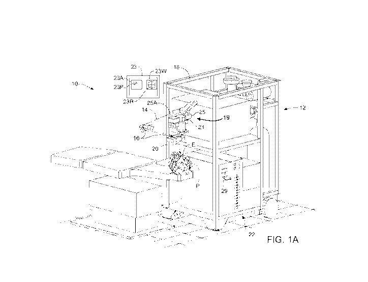
[0090] Referring now to FIG. 1A, a laser eye surgery system 10 for
incorporating
embodiments of the present invention includes a laser 12 that produces a laser
beam 14. Laser
12 is optically coupled to laser delivery optics 16, which directs laser beam
14 to an eye of
patient P. A delivery optics support structure (not shown here for clarity)
extends from a frame
18 supporting laser 12. An input device 20 is used to align laser system 10
with patient P. A
microscope 21 is mounted on the delivery optics support structure. Microscope
21 comprises an
imaging system to image a cornea of eye E. The laser eye surgery system 10 may
include a
display 23 that provides an image of eye E that is visible to the user. A
video camera 25 can be
21
CA 03033355 2019-02-07
WO 2018/031812
PCT/US2017/046355
optically coupled to microscope 21 to provide an image of the eye E on the
display as seen
through the microscope.
[0091] Microscope 21 transmits visible light, and the operator can view tissue
auto-
fluorescence of the epithelial layer while the laser ablates corneal tissue.
The operator can
interrupt the treatment in response to penetration of the epithelial layer,
for example by lifting a
foot switch pedal. Microscope 21 may comprise at least one lens to form an
optical image of the
tissue fluorescence that is visible to the operator such that the operator can
detect penetration of
the epithelial layer based on the optical feedback. In some embodiments, video
camera 25
comprises a camera sensitive to visible light and at least a portion of the
epithelial fluorescence
comprises visible light, such that epithelial fluorescence can be seen with
video camera 25. In
some embodiments, a second video camera 25A can be coupled to microscope 21.
Second
camera 25A comprises a sensor sensitive to UV light to detect epithelial
fluorescence. Second
camera 25A can be triggered off the laser fire signal, such that each pulse of
the treatment can be
shown on the display, for example fluorescence from individual pulse 23P.
Second video
camera 25A may comprise an electronic shutter synchronized to the laser
trigger such that the
shutter is open for no more than about 1 ms, for example no more than 100
i.ts, or even no more
than 50 i.ts, when the laser fires to enhance visibility of the epithelial
fluorescence. Although a
microscope is shown, in some embodiments a camera lens can be used to image
the tissue
fluorescence, such that the image of the tissue fluorescence can be shown on
the display.
[0092] In some embodiments, the laser pulses may be sorted such that the user
can see
penetration of the epithelial layer, as described in U.S. Pat. App. No.
60/865,342, filed
November 10, 2006, entitled, "Operator-Controlled Scanning Laser Procedure
Designed for
Large-Area Epithelium Removal," the full disclosure of which is incorporated
herein by
reference.
[0093] In some embodiments the laser may automatically detect penetration of
the epithelial
layer as described in U.S. Pat. Nos. 5,505,724; 6,019,755; and 6,293,939
entitled "Epithelium
Removal".
[0094] In many embodiments, a sudden reduction in fluorescence, for example
either an
average amount or a number of pixels of an image of fluorescence, can be
measured and used to
find and/or determine breakthrough, for example penetration, of the epithelial
layer, for example
22
CA 03033355 2019-02-07
WO 2018/031812
PCT/US2017/046355
when the measured fluorescence decreases from a first value above a threshold
fluorescence
amount to a second value below the threshold fluorescence amount so as to
indicate penetration
and/or breakthrough of the epithelial layer. In response to the detected
penetration and/or
breakthrough, the treatment algorithm and/or treatment program may stop
ablation for safety
and/or may change treatment modes, for example to selectively ablate
epithelium and/or to
perform a refractive ablation of the stroma. Systems and methods of detecting
at least one of
penetration, breakthrough or clearance of the epithelial layer and automated
removal of the
epithelium in response to epithelial fluorescence are described in U.S. Pat.
No. 8,926,600, the
full disclosure of which is incorporated herein by reference. In various
embodiments, the laser
eye surgery system 10 includes at least some portions of a STAR S4 JRTM
Excimer Laser System
with Variable Spot Scanning (VSSTm). In some embodiments, the laser eye
surgery system 10
includes at least some portion of a WaveScan WaveFront System or an iDesign
System
available from AMO Manufacturing USA, LLC, Milpitas, California, the Wavelight
Allegretto
laser system, Wavelight Analyzer II, and Wavelight TopolyzerTm diagnostic
system
commercially available from Alcon, a Novartis division, of Forth Worth; TX,
the Zyoptix
Systems commercially available from Bausch & Lomb of Bridgewater, New Jersey;
the EC-
5000 Series of excimer laser systems commercially available from NIDEK of
Gamagori, Japan,
the OPD Scan III also available from NIDEK; and the MEL 8OTM Excimer Laser,
WASCATM
analyzer, and Atlas 9000 system, all commercially available from Carl Zeiss
Meditec, Inc. of
Dublin, California. One embodiment includes a WaveScan system with a
deformable mirror.
An alternate embodiment of a wavefront measuring system is described in U.S.
Patent No.
6,271,915, the full disclosure of which is incorporated herein by reference.
It is appreciated that
any wavefront aberrometer could be employed for use with embodiments of the
present
invention. Relatedly, embodiments of the present invention encompass the
implementation of
any of a variety of optical instruments provided by Abbott Medical Optics
Inc., including the
iDesign system, and the like.
[0095] Relatedly, embodiments of the present invention encompass the
implementation of any
of a variety of optical instruments provided by WaveFront Sciences, Inc.,
including the COAS
wavefront aberrometer, the ClearWave contact lens aberrometer, the CrystalWave
IOL
.. aberrometer, and the like. Embodiments of the present invention may also
involve wavefront
measurement schemes such as a Tscherning-based system, which may be provided
by Alcon.
23
CA 03033355 2019-02-07
WO 2018/031812
PCT/US2017/046355
Embodiments of the present invention may also involve wavefront measurement
schemes such
as a ray tracing-based system, which may be provided by Tracey Technologies,
Corp.
[0096] Laser eye surgery system 10 may comprise an eye tracker 19. Eye tracker
19 may
comprise, for example, an eye tracker as commercially available in the STAR S4
IRTM Excimer
Laser System with Variable Spot Scanning (VSSTm). Eye tracker 19 may comprise
optical
components microscope 21. The eye tracking system may comprise at least some
optical
components separate from the microscope, for example as described in U.S. Pat.
No. 6,322,216.
Eye tracker 19 can be in communication with the embedded computer so as to
offset the position
of the laser beam pulse in response to a measured position of the eye. The
processor may
comprise a processor system with at least one processor, for example a
plurality of processors,
such as a processor for tracking the eye, a processor to control the laser and
at least one
processor to control positions of scanning elements, sensors and laser firing.
The processor
system may comprise a distributed processor system with a first processor to
calculate a
treatment table, for example at a research facility, and a second processor,
for example of the
laser system, to ablate the eye with the treatment table from the first
processor. In some cases,
one processor may be implemented in or coupled with a diagnostic device (e.g.
wavefront
aberrometer) and another processor may be implemented in or coupled with a
laser delivery
device. In some cases, a separate processor may be implemented in or coupled
with a device that
measures and/or calculates epithelial thickness. In some cases, a separate
processor may be
implemented in or coupled with a device that calculates an epithelial removal
treatment. In some
cases, a single processor or processor system can perform any of the
calculations,
determinations, or method steps disclosed herein. In some cases, systems as
disclosed herein
may include one or more processors or processor systems.
[0097] The display 23 may comprise windows to show images of the eye, for
example a first
window 23W and a second window 23A. First window 23W can be coupled to video
camera 25
to show the image of the eye E as seen through the operating microscope. First
window 23W
may show structures visible to the operator, for example a reticule 23R, and
the image of the eye
including the iris and pupil. Video camera 25 may comprise a color video
camera to show a
color image of the eye to the operator on the display. Second window 23A can
be coupled to
second video camera 25A. The second video camera 25A can be coupled to a frame
grabber of
24
CA 03033355 2019-02-07
WO 2018/031812
PCT/US2017/046355
the embedded processor to grab an image for each pulse of the laser treatment
and display the
image from each pulse in second window 23A of the display, so as to minimize
dropped frames
and facilitate detection of penetration through the epithelium. The camera
synchronized to the
laser beam pulse can improve epithelial fluorescence imaging and may be used
for detection of
penetration where the display is shown to an operator and/or where the laser
pulse firing is
stopped automatically. Although reference is made to a video camera, the
fluorescence sensor
can comprise many known sensors sensitive to fluorescence such as at least one
of an area
sensor, a line sensor, a CCD array, a gated image intensifier, photomultiplier
tube, a photodiode,
a phototransistor or a cascade detector.
[0098] While the input device 20 is here schematically illustrated as a
joystick, it should be
understood that a variety of input mechanisms may be used. Suitable input
mechanisms may
include trackballs, touch screens, foot-pedals or a wide variety of
alternative pointing devices.
Still further alternative input mechanisms include keypads, data transmission
mechanisms such
as an Ethernet, intranet, internet, a modem, or the like.
[0099] Laser 12 generally comprises an excimer laser, ideally comprising an
argon-fluorine
laser producing pulses of laser light having a wavelength of approximately 193
nm. The pulses
of laser light typically have a fixed pulse duration having a full width half
maximum (FWHM) of
about 15 nanoseconds during a treatment. Laser 12 is preferably designed to
provide a feedback
stabilized fluence at the patient's eye, delivered via delivery optics 16.
Embodiments of the
present invention may also be useful with alternative sources of ultraviolet
or infrared radiation,
particularly those adapted to controllably ablate the corneal tissue without
causing significant
damage to adjacent and/or underlying tissues of the eye. The laser system may
include, but is not
limited to, excimer lasers such as argon-fluoride excimer lasers (producing
laser energy with a
wavelength of about 193 nm), solid state lasers, including frequency
multiplied solid state lasers
such as flash-lamp and diode pumped solid state lasers. Exemplary solid state
lasers include UV
solid state lasers (approximately 193-215 nm) such as those disclosed in U.S.
Patent Nos.
5,144,630 and 5,742,626; Borsurtky et al., "Tunable UV Radiation at Short
Wavelengths (188-
240 nm) Generated by Sum Frequency Mixing in Lithium Borate," Appl. Phys.
61:529-532
(1995), and the like. The laser energy may comprise a beam formed as a series
of discreet laser
pulses. A variety of alternative lasers might also be used. Hence, although an
excimer laser is
CA 03033355 2019-02-07
WO 2018/031812
PCT/US2017/046355
the illustrative source of an ablating beam, other lasers may be used in
embodiments of the
present invention.
[0100] Laser 12 and delivery optics 16 generally direct laser beam 14 to the
eye E of patient P
under the direction of a computer 22. Computer 22 will often selectively
adjust laser beam 14 to
expose portions of the cornea to the pulses of laser energy so as to effect a
predetermined
sculpting of the cornea and alter the refractive characteristics of the eye.
In some embodiments,
both laser 14 and the laser delivery optical system 16 will be under computer
control of
processor system 22 to effect the desired laser sculpting process, with the
processor system
effecting (and optionally modifying) the pattern of laser pulses. In some
embodiments, a
treatment plan is developed to treat a layer of tissue, and the treatment plan
can be defined with a
pattern of laser beam pulses. For example, a treatment plan to ablate the
epithelial layer may
comprise a pattern of laser beam pulses applied to the epithelial layer, and a
treatment plan to
ablate the stromal tissue may comprise a pattern of stromal laser beam pulses
applied to the
stromal layer. The pattern of pulses may by summarized in machine readable
data of tangible
media 29 in the form of a treatment table. Although tangible media 29 is
illustrated having a
particular form factor in Figure 1A, it should be understood that any form of
tangible media may
store information indicating the pattern of pulses used to ablate the stromal
tissue and/or the
epithelial layer, or any other machine instructions and/or data discussed
herein. The treatment
table may be adjusted according to feedback input into processor system 22
from an automated
image analysis system (which automated image analysis system may be, for
example, manually
installed into the processor system by a system operator) in response to
feedback data provided
from an ablation monitoring system feedback system. Such feedback might be
provided by
integrating the wavefront measurement system described below with the laser
treatment system
10, and processor system 22 may continue and/or terminate a sculpting
treatment in response to
the feedback, and may optionally also modify the planned sculpting based at
least in part on the
feedback.
[0101] Laser beam 14 may be adjusted to produce the desired sculpting using a
variety of
alternative mechanisms. The laser beam 14 may be selectively limited using one
or more
variable apertures. An exemplary variable aperture system having a variable
iris and a variable
width slit is described in U.S. Patent No. 5,713,892. The laser beam may also
be tailored by
26
CA 03033355 2019-02-07
WO 2018/031812
PCT/US2017/046355
varying the size and offset of the laser spot from an axis of the eye, as
described in U.S. Patent
Nos. 5,683,379, and 6,203,539.
[0102] Still further alternatives are possible, including scanning of the
laser beam over a
surface of the eye and controlling the number of pulses and/or dwell time at
each location, as
described, for example, by U.S. Patent No. 4,665,913; using masks in the
optical path of laser
beam 14 which ablate to vary the profile of the beam incident on the cornea;
hybrid profile-
scanning systems in which a variable size beam (typically controlled by a
variable width slit
and/or variable diameter iris diaphragm) is scanned across the cornea; or the
like. The computer
programs and control methodology for these laser pattern tailoring techniques
are well described
in the patent literature.
[0103] Additional components and subsystems may be included with laser system
10, as
should be understood by those of skill in the art. For example, spatial and/or
temporal
integrators may be included to control the distribution of energy within the
laser beam, as
described in U.S. Patent No. 5,646,791. An ablation effluent evacuator/filter
and other ancillary
components of the laser surgery system which are not necessary to an
understanding of the
invention need not be described in detail for an understanding of the present
invention.
[0104] Processor system 22 may comprise (or interface with) a conventional PC
system
including the standard operator interface devices such as a keyboard, a
display monitor, and the
like. Processor system 22 typically includes an input device such as a
magnetic or optical disk
drive, an internet connection, or the like. Such input devices will often be
used to download a
computer executable code from a tangible storage media 29 embodying any of the
methods of
the present invention. Tangible storage media 29 may take the form of a floppy
disk, an optical
disk, a data tape, a volatile or non-volatile memory, or the like, and the
processor system 22
includes the memory boards and other standard components of modern computer
systems for
storing and executing this code. Tangible storage media 29 may optionally
embody wavefront
sensor data, wavefront gradients, a wavefront elevation map, a treatment map,
a corneal
topography map, a measurement of refraction of the eye, pupil images of the
eye such as iris
registration data, epithelial map data, and/or an ablation table.
[0105] FIG. 1B illustrates profiles of mapped tissue structures of an eye,
according to
embodiments of the present invention. An eye E comprises an epithelium or
epithelial layer,
27
CA 03033355 2019-02-07
WO 2018/031812
PCT/US2017/046355
Bowman's membrane, a stroma/stromal layer under Bowman's membrane, and an
endothelial
layer. As Bowman's membrane is substantially collagenous and has a poorly
defined posterior
boundary with the stromal layer, at least a portion of Bowman's membrane can
be considered a
part of the stromal layer in some embodiments of the present invention. Eye E
includes an iris
that defines a pupil. The epithelial thickness above the stromal layer and
Bowman's membrane
is mapped and has as a central thickness El and a peripheral thickness E2. In
some
embodiments, several thickness measurements are made along a tissue section to
profile the
thickness along the section, and several sections are measured to provide a
map of epithelial
thickness along two dimensions over the pupil of the eye. In some embodiments,
several optical
coherence tomography (hereinafter "OCT")scans are made along tissue sections
to map the
epithelium. In some embodiments, Scheimpflug images are measured along tissue
sections and
combined to make a three dimensional map. The maps can be shown as three
dimensional maps
of corneal thickness with the first two dimensions corresponding to transverse
positions on the
eye and the third dimension corresponding to the thickness of the epithelial
layer at locations
.. along the first two dimensions. In some embodiments, the thickness of
additional structures are
mapped, for example thickness of the stromal layer defined by a distance from
Bowman's
membrane to the endothelial layer, a thickness of the crystalline lens and/or
a length of the eye.
[0106] An ablation of a region of a cornea of an eye using an arrangement of
pulses 14a-14e of
a scanning laser beam is illustrated in FIG. 1C. The arrangement of pulses is
applied to positions
over a region 15 of a cornea C of an eye E. As illustrated in FIG. 1A, pulses
14e and 14d
overlap. A dimension across pulse 14c is smaller than a dimension across pulse
14b. The
arrangement of pulses 14a to 14e corresponds to the coordinate position and
size of each pulse.
The arrangement can be ordered to define a sequential series of pulses 14a to
14e that is
sequentially applied to eye E in accordance with a treatment table listing.
The treatment table
.. lists the coordinates and sizes of the laser beam for each pulse.
Mathematically, an arrangement
of pulses in a treatment table may correspond to a pulse instruction vector
(hereinafter "Ply")
that represents the laser instruction for each pulse. Systems and methods for
determining an
arrangement of laser beam pulses with basis functions are described in U.S.
Pat. No. 7,008,415,
the full disclosure of which is incorporated herein by reference.
28
CA 03033355 2019-02-07
WO 2018/031812
PCT/US2017/046355
[0107] A sequential series of pulses that ablates the epithelial layer to a
desired shape can be
referred to as an epithelial series of pulses. In some embodiments, an
epithelial series of pulses
can be used to ablate the epithelial layer, for example to provide access to
at least one of the
stromal layer or Bowman's membrane. The epithelial series of pulses may be
arranged to ablate
the epithelial layer in response to the mapped thickness of the epithelial
layer.
[0108] An additional ablation procedure can then be ablated into at least one
of the stromal
corneal tissue or Bowman's membrane to provide a refractive correction with a
stromal
arrangement of pulses. A sequential series of pulses that ablates the stromal
layer can be referred
to as a stromal series of pulses.
[0109] In some embodiments, some of the pulses may simultaneously ablate
epithelial tissue
and Bowman's membrane and/or stromal tissue, and such pulses may be referred
to as crossover
pulses. Crossover pulses may occur when the epithelial layer is partially
removed and the laser
beam pulse irradiates residual epithelial tissue and exposed Bowman's membrane
tissue and/or
stromal tissue with the same pulse. As the corneal stroma, like the Bowman's
membrane,
includes substantially acellular collagenous tissue and collagenous tissue
fibers, ablation of
Bowman's membrane can be modeled with stromal ablation basis functions. Also,
in some
embodiments, Bowman's membrane may comprise a thickness of two to three
microns such that
modeling of Bowman's tissue as stromal tissue may have a minimal impact on
error in the
ablated shape.
[0110] In some embodiments, the epithelial layer can be ablated with
epithelial pulses until
penetration of the stroma is detected with crossover epithelial pulses that
simultaneously ablate
epithelial tissue and Bowman's tissue and/or stromal tissue, and the operator
may pause the
treatment. The treatment can be resumed with stromal pulses and the stromal
layer can be
subsequently ablated with stromal pulses. The epithelium may be allowed to
grow back over the
stroma following stromal ablation with stromal pulses.
[0111] The treatment table can be sorted in many ways. In some embodiments,
the epithelial
series of pulses is applied to the epithelial layer and the stromal series of
pulses applied to the
stromal layer. In some embodiments, the pulses are sorted such that some of
the pulses from the
stromal series are applied to the epithelial layer and some of the pulses from
the epithelial series
are applied to the stromal layer. The stromal pulses may be combined with the
epithelial pulses
29
CA 03033355 2019-02-07
WO 2018/031812
PCT/US2017/046355
such that the stromal pulses are interspersed, or mixed, between the
epithelial pulses by sorting,
such that many epithelial pulses are applied to the stromal tissue layer after
the epithelial layer is
ablated and many stromal pulses are applied to the epithelial layer before the
stromal layer is
ablated.
[0112] In some embodiments, the epithelium and stroma can be ablated to remove
corneal
haze with minimal intended impact on the refraction of the eye.
[0113] Referring now to FIG. 2, laser beam delivery system 16 for directing
laser beam 14 at
eye E will often include a number of mirrors 30, as well as one or more beam
homogenizers.
The laser beam homogenizers can even (or otherwise tailor) the laser energy
distribution across
the laser beam with spatial and temporal integration. Spatial integration can
include overlapping
portions of the laser beam with prisms, diffractive optics, lenses and the
like. In some
embodiments, a hexagonal array of prisms 36 separates laser beam 14 into a
plurality of
beamlets, which may partially overlap on eye E to smooth edges of the ablation
or "crater" from
each pulse of the laser beam. Temporal integration can include moving the
beam, for example
with rotation with dove prisms, K-mirrors, cylindrical lens pairs and the
like. In some
embodiments, temporal integrator 32, may comprise a dove prism. Laser 12 will
often comprise
an excimer laser as described above. Apparatus for laser beam homogenization
are described in
U.S. Patents 5,646,791; 5,912,775; 6,816,316 and 7,206,132.
[0114] In some embodiments, a variable aperture 34 changes a diameter and/or
slot width
profile of laser beam 14. In specific embodiments, the variable aperture
includes both a variable
diameter iris and a variable width slot. Variable aperture 34 may comprise a
variable diameter
iris and/or a plurality of apertures on a movable structure such as a plate or
wheel. In some
embodiments that scan the laser beam over the eye with offset of the laser
beam, a variable sized
circular aperture may provide correction of astigmatism and wavefront
aberrations, optionally
without the variable slot.
[0115] Referring now to Figs. 2 and 3, an offset module 38 may include motors
40 which vary
an angular offset of an offset lens 42, and which also change the radial
orientation of the offset.
Hence, offset module 38 can selectively direct laser beam 14 at a desired
lateral region of the
cornea. A structure and method for using laser beam delivery system 16 and
offset module 38
are more fully described in U. S. Patent Nos. 6,984,227; 6,331,177; 6,203,539;
5,912,775; and
CA 03033355 2019-02-07
WO 2018/031812
PCT/US2017/046355
5,646,791. In some embodiments, the offset module may comprise scanners with
movable
mirror that are controlled with galvanometer current measurements, as
described in U.S. Patent
Nos. 4,718,418; 4,665,913 and 5,480,396.
[0116] Referring now to FIG. 4, a control system of a laser system 10 is
schematically
illustrated according to the principles of the present invention. A processor
system 22 enables
precise control of laser system 10 to sculpt a surface shape specified in a
laser treatment table 52.
A processor system 22, which generally comprises a PC workstation, makes use
of a computer
program stored on a tangible media 29 to generate treatment table 52.
Processor system 22 may
include a library 44 of treatments and treatment tables as described in U.S.
Patent Nos.
6,245,059; and 7,077,838. In some embodiments, processor system 22 may
additionally include
several basis data profiles and programs to calculate simulated ablation
shapes and determine a
sequence of laser beam pulses. An embedded computer 58 within laser system 10
is in
electronic communication with the PC workstation. Alternatively, a PC
workstation may be
embedded in the laser system and include an embedded processor card in
communication with
the PC workstation for directing the ophthalmic surgery. The eye tracker 19,
as described above,
can be connected to embedded computer 58. Video camera 25 and second video
camera 25A
can be optically coupled to microscope 21, as described above, and connected
to display 23 to
show images of the eye to the surgeon and/or system operator.
[0117] Embedded computer 58 is in electronic communication with a plurality of
sensors 56
and a plurality of motor drivers 60. The motor drivers 60 are coupled to the
embedded computer
58 to vary the position and configuration of many of the optical components of
the delivery
optics 16 according to treatment table 52. For example, first and second
scanning axis 62, 64
control the position of the offset lens to move the beamlets over the surface
of the cornea. Iris
motor 66 controls the diameter of the overall beam, and in some cases, the
length of light
transmitted through a variable width slot. Similarly slot width driver 68
controls the width of the
variable slot. Slot angle driver 70 controls rotation of the slot about its
axis. Beam angle driver
72 controls rotation of the beam as effected by a temporal integrator as
described above.
Processor system 22 issues a command for laser 12 to generate a pulse of the
laser beam 14 after
the various optical elements have been positioned to create a desired crater
on eye E. Treatment
31
CA 03033355 2019-02-07
WO 2018/031812
PCT/US2017/046355
table 52 comprises a listing of all of the desired craters to be combined so
as to effect a treatment
therapy.
[0118] A timer 80 may be located on an add on card of processor system 22 and
in some
embodiments may comprise a Lab-PC-1200 model card having timers 8253/8254. The
Lab-PC-
1200 model card is available from National Instruments of Austin, TX. In
alternate
embodiments, timer 80 is located externally to processor system 22. The timer
80 is controlled
by a computer program of processor system 22 and is adapted to measure time
intervals. The
laser 12 is electronically coupled to processor system 22. Laser 12 fires upon
a command issued
from processor system 22 in response to a time interval measured by timer 80.
Processor system
22 varies the rate at which laser 12 fires during at least a portion of a
treatment of an eye E.
[0119] FIG. 5A is a schematic illustration of a system 200 for mapping
refractive optical
properties of an eye, mapping epithelial thickness of the eye, and ablating
the eye with an
arrangement of laser beam pulses, according to embodiments of the present
invention. System
200 includes a refractive properties mapping device 210. Refractive properties
mapping device
210 can map refractive optical properties of the eye, for example wavefront
elevation mapping of
the refractive properties of the entire optical train of the eye extending
from the cornea to the
retina. System 200 includes an epithelial thickness mapping device 220.
Epithelial thickness
mapping device 220 maps a thickness of the epithelial layer covering Bowman's
membrane and
the stroma. System 200 may include a corneal topography mapping device 230.
Corneal
topography mapping device 230 maps a surface topography of the front surface
of the cornea, for
example with videokeratography. In some embodiments, system 200 includes the
same device
to perform both corneal epithelial mapping and corneal topography mapping.
[0120] System 200 includes a processor system 240, with many of the components
as
described above. Processor system 240 includes epithelial basis data 242,
stromal basis data 252
and may comprise Bowman's basis data 262. Epithelial basis data 242 includes
ablation profiles
for laser beam pulses to the epithelial layer that can be used to calculate
the shape of tissue
removed from the epithelial layer for an epithelial arrangement of laser beam
pulses applied to
the epithelial layer. Stromal basis data 252 includes ablation profiles for
laser beam pulses to the
stromal layer that can be used to calculate the shape of tissue removed from
the stromal layer
with a stromal arrangement of laser beam pulses applied to the stromal layer.
Bowman's basis
32
CA 03033355 2019-02-07
WO 2018/031812
PCT/US2017/046355
data 262 includes ablation profiles for laser beam pulses to Bowman's layer
that can be used to
calculate the shape of tissue removed from Bowman's layer with a Bowman's
arrangement of
laser beam pulses applied to Bowman's layer. System 200 includes a laser eye
surgery system
250. Laser eye surgery system 250 can include many of the components described
above.
.. [0121] Processor system 240 receives as input mapped epithelial thickness
profile data from
device 220, and mapped refractive property profile data from device 210.
Processor system 240
can receive input from many additional sources to determine the treatment for
the patient, for
example patient manifest refraction, age and keratometry. Processor system 240
uses the
epithelial, stromal and/or Bowman's basis profile data to determine the
arrangement of laser
beam pulses, for example as a pulse instruction vector as described in U.S.
Pat. No. 7,008,415,
the full disclosure of which has been previously incorporated herein by
reference. Processor
system 240 outputs a laser treatment table to laser eye surgery system 250.
The laser eye surgery
system uses coordinate references in the treatment table and sizes of the
laser beam to treat the
eye.
[0122] In some embodiments, processor system 240 may comprise a distributed
processor
network that includes a plurality of processors in electronic or other
communication, for example
of the Internet, an intranet and/or local area network with wireless
communication. In specific
embodiments, an operator can carry a floppy drive from one processor to
another processor to
effect communication among the processors of the processor system. In some
embodiments,
refractive properties mapping device 210 comprises a processor; epithelial
thickness mapping
device 220 comprises a processor; and corneal topography mapping device 230
comprises a
processor and laser eye surgery system 250 comprises a processor. Processor
system 240 may
comprise the processors of any of the measurement devices and the laser eye
surgery system.
[0123] Refractive properties mapping device 210 may comprise many devices that
can be used
.. to determine the refractive properties of the optical path of the eye from
the front surface of the
cornea to the retina with subjective and/or objective measurements. In some
embodiments
refractive properties mapping device 210 comprises a Hartmann Shack wavefront
sensor, for
example as described in U.S. Pat. Nos. 6,155,684; 6,264,328; 6,271,914;
6,271,915; and
7,036,934. In some embodiments, refractive properties mapping device 210
comprises a
.. spatially resolved refractometer, for example as described in 5,258,791;
6,000,800; and
33
CA 03033355 2019-02-07
WO 2018/031812
PCT/US2017/046355
6,409,345. In some embodiments, the device to measure the eye may include
objective
measurements with a light probe beam, for example as described in U.S. Pat.
Nos. 6,409,345,
entitled "Method and Device for Synchronous Mapping of the Total Refraction
Non-
Homogeneity of the Eye and Its Refractive Components"; and 6,932,475, entitled
"Device for
Measuring Aberration Refraction of the Eye". In some embodiments, the
refractive optical
properties of the eye may be measured with an interferometer, for example as
described in U.S.
Pat. Nos. 7,084,986, entitled "System for Measuring the Optical Image Quality
of an Eye in a
Contactless Manner"; and 6,922,250, entitled "Optical Multiplex Short
Coherence Interferometry
on the Eye". In some embodiments, the optical property of the eye is measured
with an
autorefractor, for example as described in U.S. Pat. Nos. 7,001,020, entitled
"Complete
Autorefractor System in an Ultra-Compact Package"; and 5,329,322, entitled
"Palm Size
Autorefractor and Fundus Topographical Mapping Instrument". The optical
property of the eye
determined with many of these devices can be determined as a wavefront
elevation map, Zernike
coefficients, and Fourier coefficients, for example as described in U.S. Pat.
Nos. 6,299,311,
entitled "Rapid, Automatic Measurement of the Eye's Wave Aberration;
7,175,278, entitled
"Wavefront Reconstruction Using Fourier Transformation and Direct
Integration", and
7,168,807, entitled "Iterative Fourier Reconstruction for Laser Surgery and
Other Optical
Applications".
[0124] Epithelial thickness mapping device 220 may comprise many devices that
can used to
determine a thickness of the epithelial layer. In some embodiments, epithelial
mapping device
220 measures energy reflected from the interface of the epithelial layer with
Bowman's
membrane and/or the stroma. The reflected energy may comprise light energy
and/or ultrasonic
energy. In some embodiments epithelial thickness mapping device 220 comprises
an OCT
machine, for example as described in U.S. Pat. Nos. 5,491,524; 6,741,359; and
6,755,819. In
some embodiments, the epithelial thickness mapping device may comprise a high
frequency
ultrasound array, for example as described in U.S. Pat. Nos. 6,315,727;
6,949,071; 7,048,690.
Scheimpflug and other photography may also be used to map thickness of the
epithelial layer
4,523,821; 5,512,965; 6,286,958; 6588903. In some embodiments, epithelial
mapping device
220 may comprise a con-focal microscope, for example as described in U.S. Pat.
Nos. 5,359,373
and 6,118,580. In some embodiments, epithelial mapping device 220 may measure
a thickness
of Bowman's membrane, and the thickness data of Bowman's membrane may be
communicated
34
CA 03033355 2019-02-07
WO 2018/031812
PCT/US2017/046355
within processor system 240 and used to determine an arrangement of laser beam
pulses to ablate
Bowman's membrane.
[0125] In some embodiments, epithelial mapping device 220 comprises an imaging
system to
image the iris of eye E while the epithelium is mapped. The mapped epithelial
thickness profile
can then be registered and/or stored with the epithelial thickness profile so
as to permit
registration of the mapped epithelium with the iris. The registration of the
mapped epithelium
can occur while the epithelial thickness is mapped and/or during ablation of
the region of the
eye. Examples of systems and methods to register an image of the iris of the
eye during laser
ablation are described in U.S. Pat. No. 7,044,602, entitled "Methods and
Systems for Tracking a
Torsional Orientation and Position of an Eye". In some embodiments, the
processor system may
adjust the arrangement of laser beam pulses in real time in response to
torsional alignment of the
eye while the patient is treated with the therapeutic laser beam.
[0126] Corneal topography mapping device 230 may comprise many devices that
can be used
to measure and/or map topography of the corneal surface. In some embodiments
corneal
topography mapping device 230 can comprise a machine that analyzes images
reflected from the
eye to determine the topography map of the anterior surface of the cornea as
described, for
example, in U.S. Pat. Nos. 4,692,003; 4,863,260; 5,062,702; and 5,841,511. In
some
embodiments, corneal topography mapping device 230 comprises fluorescence that
analyzes the
position fluorescence from a pattern projected on the eye to determine the
shape of the front
surface of the eye as described, for example, in U.S. Pat. Nos. 4,761,071;
4,995,716; 5,159,361;
6,592,574; 6613041; and 6,666,857. In some embodiments, the system that maps
one or more of
the epithelial thickness, the refractive properties of the retina, and the
corneal topography is not
the same system as the system that applies the laser eye surgery. Thus,
instead of actively
performing these functions, the system 200 may instead receive that data (the
refractive
properties, epithelial thickness map, and/or corneal topography) pre-
determined from another
system and may perform laser eye surgery based on that data as described
elsewhere herein.
Stated differently, the refractive properties mapping device 210, epithelial
thickness mapping
device 220, and corneal topography mapping device 230 are considered optional
in Figure 5A.
[0127] FIG. 5B is a schematic illustration of epithelial basis data 242 used
to determine an
arrangement of laser beam pulses to ablate an epithelial layer with an
epithelial ablation profile,
CA 03033355 2019-02-07
WO 2018/031812
PCT/US2017/046355
according to embodiments of the present invention. Epithelial basis data 242
includes profiles of
epithelial basis data for small, medium and large beam diameters, for example
2, 4 and 6 mm
beam diameters respectively. A coordinate reference system 242X, 242Y, and
242Z shows
dimensions of the basis ablation profile data. Each of the profiles shows a
characteristic ablation
for a single pulse of the laser beam at the specified diameter. A peripheral
portion of each basis
ablation profile corresponds to a concave ablation in tissue and comprises
concave surface
curvature with localized negative optical power. An inner portion of each
basis ablation profile
may correspond to a concave, convex or flat localized ablation surface
curvature in tissue
depending on the size and characteristics of the laser beam and type of tissue
ablated. In some
embodiments, the inner portion can be concave with concave surface curvature,
for example with
1 mm beam diameters and with Gaussian laser beam profiles. In some embodiments
with flat
top or uniform laser energy distribution laser beams with diameter greater
than about 3 mm, the
inner portion of the ablation may comprise localized flat and convex surface
curvature while the
peripheral portion of the ablation comprises localized concave surface
curvature. In some
embodiments, the inner portion comprises a flat central sub-portion with flat
curvature (i.e. no
curvature or zero curvature) and a peripheral inner sub-portion with convex
curvature.
[0128] Small pulse ablation profile 242A illustrates ablation profile data for
a small diameter
laser beam. Small diameter pulse ablation profile 242A comprises an inner
portion 246A and an
annular peripheral portion 244A. Annular peripheral portion 244A comprises a
concave surface
curvature ablated with a peripheral portion of the laser beam. Inner portion
246A comprises a
concave surface curvature ablated with a central portion of the laser beam.
[0129] Medium pulse ablation profile 242B illustrates a profile for a medium
diameter laser
beam. Medium diameter pulse ablation profile 242B comprises an inner portion
246B and an
annular peripheral portion 244B. Annular peripheral portion 244B comprises a
concave surface
ablated with a peripheral portion of the laser beam. Inner portion 246B
comprises flat and
convex surface curvatures ablated with a central portion of the laser beam,
and inner portion
246B is ablated to a lesser depth than peripheral portion 244B. Inner portion
246B comprises a
central sub-potion with flat curvature and a peripheral convex sub-portion
with convex
curvature.
36
CA 03033355 2019-02-07
WO 2018/031812
PCT/US2017/046355
[0130] Large pulse ablation profile 242C illustrates a profile for a large
diameter laser beam.
Large diameter pulse ablation profile 242C comprises an inner portion 246C and
an annular
peripheral portion 244C. Annular peripheral portion 244C comprises a concave
surface
curvature ablated with a peripheral portion of the laser beam. Inner portion
246C comprises flat
and convex surface curvatures ablated with a central portion of the laser
beam. Such profiles can
be obtained with a uniform laser beam having a top hat energy distribution
profile, although
many laser beams and energy distributions can be used, for example multi-laser
beam energy
distribution profiles, for example as described in U.S. Pat. No. 6,984,227.
Inner portion 246C
comprises a central sub-potion with flat curvature and a peripheral convex sub-
portion with
convex curvature.
[0131] Epithelial basis data 242 can be generated empirically with
experimental measurements
from patients. For example, the shape of epithelial tissue can be measured in
situ with corneal
topography on a population of patients who undergo trans-epithelial PRK. For
each pulse
diameter profile approximately 10 patients are measured. For example, with
basis ablation
profiles for each of 1, 2, 3, 4, 5 and 6 mm, 10 patients are measured for a
total of 60 patients.
Basis data for smaller sized laser beams may also be measured. The corneal
epithelial layer may
be measured prior to laser ablation with mapping as described above. The shape
of the front
surface of the cornea can be measured intra-operatively prior to ablation, and
then measured
subsequently during ablation with many of the corneal topography mapping
devices described
above. The shape of tissue removed with the fixed size laser beam is then
measured for each
patient to empirically determine the basis data for the fixed laser beam
diameter used. The
epithelial tissue can then be removed in many ways, for example mechanically
and/or chemically
and normal PRK performed.
[0132] FIG. 5C is a schematic illustration of stromal basis data 252 used to
determine an
arrangement of laser beam pulses to ablate a stromal layer with a stromal
ablation profile,
according to embodiments of the present invention. Stromal basis data 252 can
be obtained with
many of the laser beams and methods described with respect to the epithelial
ablation data.
Stromal basis data 252 comprises small diameter pulse ablation profile 252A,
medium diameter
pulse profile 252B and large diameter pulse profile 252C. In some embodiments
the diameters
of the small, medium and large diameter pulses are 2, 4 and 6 mm,
respectively.
37
CA 03033355 2019-02-07
WO 2018/031812
PCT/US2017/046355
[0133] Small pulse ablation profile 252A illustrates ablation profile data for
a small diameter
laser beam. Small diameter pulse ablation profile 252A comprises an inner
portion 256A and an
annular peripheral portion 254A. Annular peripheral portion 254A comprises a
concave surface
ablated with a peripheral portion of the laser beam. Inner portion 256A
comprises a concave
surface curvature ablated with a central portion of the laser beam.
[0134] Medium pulse ablation profile 252B illustrates a profile for a medium
diameter laser
beam. Medium diameter pulse ablation profile 252B comprises an inner portion
256B and an
annular peripheral portion 254B. Annular peripheral portion 254B comprises a
concave surface
curvature ablated with a peripheral portion of the laser beam. Inner portion
256B comprises flat
and convex surface curvatures ablated with a central portion of the laser
beam. Inner portion
256B comprises a central sub-potion with flat curvature and a peripheral
convex sub-portion
with convex curvature.
[0135] Large pulse ablation profile 252C illustrates a profile for a large
diameter laser beam.
Large diameter pulse ablation profile 252C comprises an inner portion 256C and
an annular
peripheral portion 254C. Annular peripheral portion 254C comprises a concave
surface ablated
with a peripheral portion of the laser beam. Inner portion 256C comprises flat
and convex
surface curvatures ablated with a central portion of the laser beam. Inner
portion 256C
comprises a central sub-potion with flat curvature and a peripheral convex sub-
portion with
convex curvature.
[0136] In some embodiments, the basis profiles for the epithelial layer and
stromal layer are
different for similar beam diameters. For example, the central depth of
ablation can be different,
and the size of the inner portion flat and convex curvatures may be different.
[0137] FIG. 5D is a schematic illustration of Bowman's basis data 262 used to
determine an
arrangement of laser beam pulses to ablate a Bowman's layer with a Bowman's
ablation profile,
according to embodiments of the present invention. Bowman's basis data 252 can
be obtained
with many of the laser beams and methods described with respect to the
epithelial and stromal
ablation data. Bowman's basis data 262 comprises small diameter pulse ablation
profile 262A,
medium diameter pulse profile 262B and large diameter pulse profile 262C. In
some
embodiments the diameters of the small, medium and large diameter pulses are
2, 4 and 6 mm,
respectively.
38
CA 03033355 2019-02-07
WO 2018/031812
PCT/US2017/046355
[0138] Small pulse ablation profile 262A illustrates ablation profile data for
a small diameter
laser beam. Small diameter pulse ablation profile 262A comprises an inner
portion 266A and an
annular peripheral portion 264A. Annular peripheral portion 264A comprises a
concave surface
ablated with a peripheral portion of the laser beam. Inner portion 266A
comprises a concave
surface curvature ablated with a central portion of the laser beam.
[0139] Medium pulse ablation profile 262B illustrates a profile for a medium
diameter laser
beam. Medium diameter pulse ablation profile 262B comprises an inner portion
266B and an
annular peripheral portion 264B. Annular peripheral portion 264B comprises a
concave surface
curvature ablated with a peripheral portion of the laser beam. Inner portion
266B comprises flat
and convex surface curvatures ablated with a central portion of the laser
beam. Inner portion
266B comprises a central sub-potion with flat curvature and a peripheral
convex sub-portion
with convex curvature.
[0140] Large pulse ablation profile 262C illustrates a profile for a large
diameter laser beam.
Large diameter pulse ablation profile 262C comprises an inner portion 266C and
an annular
peripheral portion 264C. Annular peripheral portion 264C comprises a concave
surface ablated
with a peripheral portion of the laser beam. Inner portion 266C comprises flat
and convex
surface curvatures ablated with a central portion of the laser beam. Inner
portion 266C
comprises a central sub-potion with flat curvature and a peripheral convex sub-
portion with
convex curvature.
[0141] In some embodiments, the basis profiles for the epithelial layer,
stromal layer and
Bowman's layer are different for the similar beam diameters. For example, the
central depth of
ablation can be different, and the size of the inner portion flat and convex
curvatures may be
different for each of the three tissue layers.
[0142] FIG. 5E is a schematic illustration of a target epithelial ablation
profile 270 and an
estimated epithelial ablation profile 272 determined by combining the
epithelial basis data with
an epithelial arrangement of laser beam pulses, according to embodiments of
the present
invention. Target epithelial ablation profile 270 can be obtained in many
ways; for example, by
mapping the epithelium as described above, or by an operator inputting a
desired depth of
ablation for a uniform epithelial thickness. The processor system then uses
the target ablation
shape and the epithelial basis data profiles to determine an arrangement of
laser beam pulses that
39
CA 03033355 2019-02-07
WO 2018/031812
PCT/US2017/046355
will remove tissue to the target profile 270. The processor system combines
the arrangement of
laser beam pulses with the profile of each laser beam pulse and adds the
profiles for each pulse
together to obtain the estimated epithelial ablation profile 272. Although the
estimated ablation
profile 272 can be obtained in many ways, in an embodiment the estimated
ablation profile is
calculated by adding the epithelial ablation basis profile for each pulse of
the treatment together
with the other pulses of the treatment to determine the estimated ablation
depth 272. The
arrangement of laser beam pulses for a given set of epithelial basis data and
target ablation shape
can be calculated in many ways, for example with techniques similar to those
described in U.S.
Pat. No. 7,008,415, the whole disclosure of which has been previously
incorporated herein by
.. reference.
[0143] FIG. 5F is a schematic illustration of a target stromal ablation
profile 280 and an
estimated stromal ablation profile 282 determined by combining the stromal
basis data with a
stromal arrangement of laser beam pulses, according to embodiments of the
present invention.
Target stromal ablation profile 280 can be defined in many ways, for example,
with wavefront
elevation mapping of the refractive error along the optical path of the eye,
manifest refraction of
the eye, cycloplegic refraction of the eye, and autorefractor refraction of
the eye. The processor
system uses the target stromal ablation profile and the stromal basis profiles
as described above
to determine an arrangement of laser beam pulses to ablate the stromal tissue
to the target
stromal ablation profile 280. Estimated stromal ablation profile 282 can be
determined by
combining the arrangement of laser beam pulses. For example, a calculation
that uses the
arrangement of laser beam pulses and the basis data for the stroma can be used
to determine
estimated stromal ablation profile 282. The processor system may calculate the
arrangement of
laser beam pulses comprised in a treatment table in many ways; for example,
with iterations
using the treatment table to determine the arrangement of pulses so that a
minimal residual error
results between the target ablation profile and estimated ablation profile.
Systems and methods
for calculating a treatment table with basis data for a target ablation shape
are described in U.S.
Pat. No. 7,008,415, the full disclosure of which has been previously
incorporated herein by
reference. In some embodiments, localized laser ablation characteristics based
on corneal
topography mapping can be used and the treatment table calculated in response
to corneal
topography, for example as described in U.S. Pat. No. 7,083,609.
CA 03033355 2019-02-07
WO 2018/031812
PCT/US2017/046355
[0144] FIG. 5G is a schematic illustration of a target Bowman's ablation
profile 290 and an
estimated Bowman's ablation profile 292 determined by combining the Bowman's
basis data
with a Bowman's arrangement of laser beam pulses, according to embodiments of
the present
invention. Target Bowman's ablation profile 290 can be obtained in many ways;
for example, by
measuring Bowman's with a con-focal microscope as described above, or by an
operator
inputting a desired depth of ablation through Bowman's membrane. The processor
system then
uses the target ablation shape and the Bowman's basis data profiles to
determine an arrangement
of laser beam pulses that will remove tissue to the target profile 290. The
processor system
combines the arrangement of laser beam pulses with the profile of each laser
beam pulse and
adds the profiles for each pulse together to obtain the estimated Bowman's
ablation profile 272.
Although the estimated ablation profile 272 can be obtained in many ways, in
an embodiment the
estimated ablation profile is calculated by adding the epithelial ablation
basis profile for each
pulse of the treatment together with the other pulses of the treatment to
determine the estimated
ablation depth 292. The arrangement of laser beam pulses for a given set of
epithelial basis data
and target ablation shape can be calculated many ways, for example with
techniques similar to
those above.
[0145] FIG. 6A is a schematic illustration of a mapped profile 310 of corneal
epithelial
thickness, according to embodiments of the present invention. Map profile 310
shows a depth or
thickness of the corneal epithelial layer in microns across the corneal
surface from -4 mm to +4
mm referenced in relation to the pupil of the eye. Mapped profile 310 shows
the profile along
one cross sectional slice of the corneal epithelial layer. In some
embodiments, several parallel
and perpendicular slices are obtained and the thickness of the epithelial
layer is mapped along
two dimensions of the eye. In some embodiments, the thickness of the
epithelial layer can be
three dimensional with two position dimensions along a pupil and/or cornea of
the eye and a
third dimension corresponding to thickness of the epithelium along the optical
axis of the eye
through the pupil.
[0146] FIG. 6B is a schematic illustration of a wavefront map profile 320 of
refractive optical
properties of the eye, according to embodiments of the present invention.
Profile 310 can be
obtained in many ways including a wavefront mapping device that maps optical
path difference
or error across the pupil in relation to a plane wave. Epithelial thickness
profile 310 can be
41
CA 03033355 2019-02-07
WO 2018/031812
PCT/US2017/046355
subtracted from wavefront map profile 320 after the epithelial profile has
been converted to
optical path length. In some embodiments, the epithelial profile can be
converted to optical path
length by multiplying the profile by the quantity (n ¨ 1) where n is the index
of refraction of the
epithelium, about 1.377. The optical path length can then be converted to
optical path difference
(hereinafter "OPD") relative to a plane by subtracting piston, or one or more
other constants,
from the optical path length such that the epithelial contribution to the
refractive optical
characteristic is determined. Epithelial contribution 322 can then be
subtracted from wavefront
map profile 320 to obtain a remainder portion 324. In some embodiments,
remainder portion
324 corresponds to curvature of the cornea, refractive power of the lens, and
optical path length
of the eye along the axis of the eye and the relative positions of the cornea,
lens and retina along
the optical path length of the eye.
[0147] FIG. 6C is a schematic illustration of a stromal ablation profile 330
to correct refractive
optical properties of the eye in response to the refractive optical properties
profile map as in FIG.
6B, according to embodiments of the present invention. Stromal ablation
profile 330 can be
calculated from wavefront map profile 320. Stromal ablation profile 330
includes remainder
portion profile 334. Remainder portion profile 334 corrects the wavefront
error of remainder
portion 324. Epithelial contribution profile 332 corrects epithelial
contribution 322 to the
wavefront map profile 320. In some embodiments, the epithelial layer may heal
over the
ablation with the post-operative thickness profile the same as the pre-
operative thickness profile,
such that ablation of the stromal layer to correct epithelial contribution 322
can provide
correction of the refractive optical properties of the eye. Hence, ablation of
the epithelial
contribution and remainder contribution can correct the optical errors of the
eye.
[0148] In some embodiments, healing of the epithelial layer and stromal layer
can impact the
final shape of the eye and optical correction that the patient receives.
Adjustment to the ablation
profile in response to estimated healing may be used.
[0149] FIG. 6D is a schematic illustration of layers of corneal tissue ablated
based on mapping
the thickness of the epithelium and mapping the refractive optical properties
of the eye,
according to embodiments of the present invention. Stromal ablation profile
330 is shown
subtracted from the anterior stromal surface and/or Bowman's surface of the
cornea. Epithelial
thickness profile 310 is shown over the surface of the cornea. One will
appreciate that in some
42
CA 03033355 2019-02-07
WO 2018/031812
PCT/US2017/046355
embodiments the epithelium will heal following ablation in the stromal layer
of profile 330, and
thickness profile 310 postoperatively will be changed in some embodiments.
[0150] FIG. 7A is a schematic illustration of a healed epithelial profile 340
of healed corneal
epithelial thickness following ablation of the profile map to correct
refractive optical properties
of the eye, according to embodiments of the present invention. Healed
epithelial profile 340 is
shown in relation to mapped epithelial profile 310. A change in profile 342
shows the change in
pre-operative epithelial profile 310 to post-operative epithelial profile 340.
Healed profile 340
and change in profile 342 and can be estimated based on empirical measurements
of a patient
population of patients who are treated. For example, a patient sample size of
100 patients can be
selected and their epithelial thickness measured preoperatively and
postoperatively to determine
an estimate of postoperative thickness and/or change in thickness of the
epithelial layer based on
the pre-operative epithelial thickness mapping and ablation characteristics.
An estimate of
healed epithelial profile 340 can be used to modify the stromal ablation
profile to determine an
adjusted stromal ablation profile. The estimated healed profile can be in
response to several
patient variables, for example age, degree of myopia, degree hyperopia, degree
of astigmatism,
race and sex. The patient population can be increased or decreased as
appropriate, depending on
the number of variables and level of statistical significance and power.
[0151] Similar measurements and estimates can be made for stromal healing
based on
empirical data, and an estimated healed stromal profile determined. In some
embodiments, the
front surface of the stromal layer and/or Bowman's membrane is determined, for
example by
subtracting the mapped epithelial thickness profile from a corneal topography
measurement.
Pre-operative corneal topography measurements and post-operative corneal
topography
measurements can be made when the epithelial layer is mapped as described
above, such that the
stromal profile can be determined from the corneal topography and mapped
epithelial layer. The
stromal ablation profile can be adjusted in response to the changes in stromal
profile and/or
epithelial profile.
[0152] FIG. 7B is a schematic illustration of an adjusted stromal ablation
profile 350 in
response to the map of estimated corneal epithelial thickness following
ablation as in FIG. 7A,
the profile map of corneal epithelial thickness as in FIG. 6A, and the profile
map of refractive
.. optical properties of the eye as in FIG. 6B, according to embodiments of
the present invention.
43
CA 03033355 2019-02-07
WO 2018/031812
PCT/US2017/046355
Adjusted stromal ablation profile 350 includes a healed epithelial
contribution 352 and remainder
portion profile 334. For comparison, stromal ablation profile 330 without the
healing adjustment
is also shown. Remainder portion profile 334 can be added to healed epithelial
profile
contribution 352 to obtain adjusted stromal ablation profile 350. Adjusted
stromal ablation
profile 350 can then be used as a target stromal ablation profile and the
arrangement of laser
beam pulses solved to ablate the stroma with this profile.
[0153] FIG. 8A is a simplified schematic illustration of an epithelial
arrangement 802 of pulses
in accordance with embodiments of the present invention. Epithelial
arrangement 802 includes a
diameter 830, an x-coordinate 840, y-coordinate 850 and a delay 860 for each
pulse of the
arrangement. A number of pulses 810 for each diameter and/or pulse number can
also be
specified for each pulse of the arrangement. A treatment table with delays,
positions and
diameters sorted to avoid tissue heating is described, for example, in U.S.
Pat. No. 7,077,838.
An illustrative epithelial treatment for epithelial mapping treatments may
include 80 pulses of 1
mm diameter, 80 pulses of 2 mm diameter, 80 pulses of 3 mm diameter, and 80
pulses of 4 mm
diameter. In some embodiments, each line in the treatment table corresponds to
a single pulse of
the laser beam, such that each pulse has its own position and delay, and the
pulse position and
delay can vary within each group of pulses. Although the illustrative
embodiment can list
positions for each pulse of the laser beam, the arrangement of pulses can be
organized as a
trajectory, or the like.
[0154] FIG. 8B is a simplified schematic illustration of a stromal arrangement
804 of pulses in
accordance with embodiments of the present invention. Stromal arrangement 804
includes
diameter 830, x-coordinate 840, y-coordinate 850 and delay 860 for each pulse
of the
arrangement. Number of pulses 810 or pulse number is also be specified for
each pulse of the
arrangement. An illustrative stromal treatment to correct epithelial and
remainder component
aberrations may include 100 pulses of 1 mm diameter, 100 pulses of 2 mm
diameter, 100 pulses
of 3 mm diameter, and 100 pulses of 4 mm diameter.
[0155] FIGS. 8C is a simplified schematic illustration of an epithelial
treatment table 806 that
comprises epithelial arrangement 802, according to embodiments of the present
invention.
Epithelial treatment table 806 comprises an epithelial sequence 870 of laser
beam pulses, which
is determined in response to epithelial mapping as described above. Epithelial
arrangement 802
44
CA 03033355 2019-02-07
WO 2018/031812
PCT/US2017/046355
can be sorted to determine epithelial sequence 870. Epithelial sequence 870
comprises pulses
sorted such that the laser beam expands from small 1 mm diameter to larger 4
mm diameter four
times during the ablation.
[0156] FIG. 8D is a simplified schematic illustration of a stromal treatment
table 808 that
comprises stromal arrangement 804, according to embodiments of the present
invention.
Stromal treatment table 808 comprises a stromal sequence 880 of laser beam
pulses, which is
determined based on the optical properties of the eye and/or healing as
described above. Stromal
arrangement 804 can be sorted to determine stromal sequence 880. Stromal
sequence 880
comprises pulses sorted such that the laser beam expands from small 1 mm
diameter to larger 4
mm diameter four times during the ablation.
[0157] FIG. 8E is a simplified schematic illustration of a sequential
treatment table 820 that
comprises epithelial sequence 870 combined with stromal sequence 880,
according to
embodiments of the present invention. Epithelial sequence 870 is located
before stromal
sequence 880 such that epithelial sequence 870 ablates the epithelial layer in
response to the
.. mapped epithelial profile as described above. Pulse sequence 870 can remove
the epithelial
layer to expose the stromal layer and/or Bowman's membrane. Subsequent to
removal of the
epithelial layer, the stromal layer is ablated to a target ablation profile as
described above. In
some embodiments, the operator is able to interrupt the treatment upon
penetration of the
epithelial layer based on visual, or other, feedback from corneal epithelial
and/or stromal
fluorescence. In some embodiments, delay 860 is increased, for example from 50
ms to 200 ms,
upon transition from epithelial sequence 870 to stromal sequence 880 to permit
the operator to
pause the treatment and mechanically remove the epithelial layer.
[0158] FIG. 8F is a simplified schematic illustration of an interleaved
treatment table 822 that
comprises epithelial sequence 870 interleaved with stromal sequence 880,
according to
embodiments of the present invention. Epithelial sequence 870 is interleaved
with stromal
sequence 880. Many pulses from stromal sequence 880 are placed at intervals
among pulses
from epithelial sequence 870 such that pulses from stromal sequence 880 are
interspersed among
pulses from epithelial sequence 870. Many of the pulses from stromal sequence
880 that are
interspersed among epithelial pulses 870 are located near the beginning
portion of the table such
that pulses from stromal sequence 880 ablate the epithelial layer. Many pulses
from epithelial
CA 03033355 2019-02-07
WO 2018/031812
PCT/US2017/046355
sequence 870 are placed at intervals among pulses from stromal sequence 880
and located near
the end portion of the table, such that pulses from epithelial sequence 870
are interspersed among
stromal pulses so as ablate the stromal layer. The laser beam expands from
small 2 mm diameter
to larger 4 mm diameter eight times during the treatment.
[0159] One will appreciate that the embodiments shown in Figs. 8A to 8F are
merely examples
of patterns, sequences, sorting techniques and treatment tables. Additional
embodiments will be
readily apparent to one or ordinary skill who will recognize variations,
alternatives and
modifications. For example, wide area pulses may be used to remove most of the
epithelium
followed by smaller pulses to remove epithelial and stromal tissue, and that
some pulses may
remove both epithelial and stromal tissue.
[0160] In some embodiments, an arrangement of pulses can be determined for
Bowman's
membrane, and Bowman's arrangement of pulses may be located within the
treatment table in
many ways. For example, the pulses that correspond to Bowman's membrane can be
located in a
treatment table at a location between epithelial pulses and stromal pulses.
The epithelial pulses
may be located near the beginning of the treatment table and stromal pulses
located near the end
of the treatment such that the location of the pulses in the treatment table
corresponds to the
tissue actually ablated with each pulse. In some embodiments, the treatment
table may be
interleaved such that Bowman's pulses are interspersed among epithelial and
stromal pulses at
many locations in the treatment table. The Bowman's pulses may be located near
the beginning
and near the end of the treatment table at locations in the treatment table
that correspond to
ablation of epithelial tissue and ablation of stromal tissue, respectively.
[0161] FIG. 9 is a flow chart that schematically illustrates a method 900 of
ablating the eye,
according to embodiments of the present invention. Method 900 includes a step
910 to map
refractive optical properties of the eye. The refractive optical properties of
the eye can be
mapped in many ways; for example, with a wavefront system that measures the
optical
properties of the entire path of the eye. A step 915 maps thickness of the
epithelial layer. The
thickness of the epithelial layer can be mapped in many ways; for example,
with an ultrasound
machine. A step 920 maps corneal topography of the eye. The corneal topography
of the eye of
the eye can be mapped in many ways, as described above. A step 925 determines
epithelial
contribution to the refractive error map of the eye. The epithelial
contribution of the refractive
46
CA 03033355 2019-02-07
WO 2018/031812
PCT/US2017/046355
map of the eye can be determined from the thickness of the epithelial layer. A
step 930
determines the remainder of contribution to the refractive map. The remainder
of contribution
can be determined by subtracting the epithelial contribution from the map of
optical properties of
the eye. A step 935 determines the healed profile of the epithelial layer. The
healed profile of
the epithelial layer can be determined in response to the ablation profile
and/or a desired optical
correction of the eye to correct optical properties of the eye. A step 945
determines stromal layer
ablation profile map. The stromal layer ablation profile map can be determined
from the healed
profile of the epithelial layer and the remainder of contribution to the
refractive map. A step 950
determines a Bowman's layer ablation profile. A step 955 determines an
arrangement of laser
beam pulses to ablate the epithelial layer. Step 955 uses epithelial basis
data as described above.
A step 960 determines an arrangement of laser pulses to ablate the stromal
layer. Step 960 uses
stromal basis data as described above. A step 965 determines an arrangement of
pulses to ablate
Bowman's layer to the profile determined in step 950. Step 965 uses Bowman's
basis data as
described above. A step 970 sorts the laser beam pulses. The pulses can be
sorted in many
ways, for example based on diameter of the pulse so that several small pulses
are ablated before
several large pulses, and several large pulses are ablated before several
small pulses several
times during the treatment. A step 975 ablates the cornea. The cornea is
ablated with the
stromal arrangement of the laser beam pulses and the epithelial arrangement of
laser beam
pulses, as described above.
[0162] It should be appreciated that the specific steps illustrated in FIG. 9
provide a particular
method of ablating the eye, according to an embodiment of the present
invention. Other
sequences of steps may also be performed according to alternative embodiments.
For example,
alternative embodiments of the present invention may perform the steps
outlined above in a
different order. Moreover, the individual steps illustrated in FIG. 9 may
include multiple sub-
steps that may be performed in various sequences as appropriate to the
individual step.
Furthermore, additional steps may be added or removed depending on the
particular applications.
In some embodiments, some, all, or none of steps 910-950 are performed. For
instance, the
method 900 need not include steps to measure the eye, such as step 910, step
915, or step 920, as
those measurements may have been taken earlier or may not be needed. As
another example,
determinations related to contributions to the refractive map (steps 925 and
930) need not be
performed as such determinations may either be unnecessary or may have been
previously
47
CA 03033355 2019-02-07
WO 2018/031812
PCT/US2017/046355
performed). Determination of the healed profile and of the various other
profiles also do not
need to be performed as that information may be unnecessary or may have been
previously
determined. It should be understood that although corneal ablation is
described as being based
on data related to specific types of corneal tissue (e.g., epithelial,
Bowman's, and stromal), the
ablation may be based on data for other types of tissue, such as scar tissue.
Thus in an
alternative, the method 900 may include receiving and/or determining scar
tissue locations and
geometry, receiving or determining basis data related to the scar tissue,
generating laser beam
pulses based on the scar tissue, and ablating the cornea based at least in
part on the laser beam
pulses generated based on the scar tissue. One of ordinary skill in the art
would recognize many
.. variations, modifications, and alternatives.
[0163] Embodiments of the present invention may use epithelial mapping without
refractive
correction to the stromal layer. For example, in some embodiments, the
epithelium may be
mapped as described above and epithelial and stromal treatments calculated to
ablate haze or
other optical irregularities from the cornea. In some embodiments, the
epithelium may be
ablated without stromal ablation to remove pathologies from the epithelium.
[0164] Figs. 10A to 10H show examples of images of epithelial fluorescence
from a patient
treatment. The images shown in Figs. 10A to 10H can be sampled from a
treatment, for example
a treatment of 1600 pulses. To obtain the images, a UV sensitive CCD camera
can be mounted
on the side of the microscope beam splitter and used to image the fluorescing
event of each
pulse, as described above. The camera may have its own frame-capture card
located in the
system controller computer. A "fire laser" signal, for example TTL (5 volt)
signal, can be sent to
the camera to trigger frame capture with each pulse, as described above. The
exposure of the
image may be timed such that the entire fluorescing event will be captured.
The exposure time
may be limited to 100iis to avoid capturing unwanted light, including
reflections from the patient
illumination and room lighting.
[0165] Fig. 10A shows a baseline image acquired when the laser is not fired
and there is no
epithelial fluorescence. Fig. 10B shows epithelial fluorescence with a first
pulse at a first
location, in which fluorescence extends across the first pulse location with
an intensity above a
threshold value. Fig. 10C shows epithelial fluorescence with a second pulse at
a second location,
in which fluorescence extends across the second pulse location with an
intensity above the
48
CA 03033355 2019-02-07
WO 2018/031812
PCT/US2017/046355
threshold value. Fig. 10D shows epithelial fluorescence with a third pulse at
a third location, in
which fluorescence extends across the third pulse location with an intensity
above the threshold
value. Fig. 10E shows epithelial fluorescence with a fourth pulse at a fourth
location, in which
fluorescence extends across the fourth pulse location with an intensity above
the threshold value.
Fig. 1OF shows epithelial fluorescence with a fifth pulse at a fifth location,
in which fluorescence
extends across a majority of the area of the fifth pulse location with an
intensity above the
threshold value, and portions of the fifth pulse location comprise
fluorescence intensity below
the threshold value so as to indicate penetration of the epithelium. Fig. 10G
shows epithelial
fluorescence with a sixth pulse at a sixth location, in which fluorescence
extends across a
minority of the area of the sixth pulse location with an intensity above the
threshold value, and
portions of the sixth pulse location comprise fluorescence intensity below the
threshold value so
as to indicate penetration of the epithelium. Fig. 10H shows epithelial
fluorescence with a
seventh pulse at a seventh location, in which fluorescence extends across a
minority of the area
of the seventh pulse location with an intensity above the threshold value, and
portions of the
seventh pulse location comprise fluorescence intensity below the threshold
value so as to
indicate penetration of the epithelium.
[0166] The images shown in 10A to 10H comprise images sampled from a portion
of the
treatment, and similar images can be acquired from each pulse of the laser
treatment for the
entire treatment, for example with the camera triggered off the laser and
coupled to the frame
grabber and shown on the display as described above. The image from each pulse
can be shown
on the display in real time, such operator is able to visualize penetration of
the epithelium with
minimal interference from visible light, for example as shown in Fig. 10A
which shows little
interference from visible light at baseline.
[0167] Plotting General Intensity of Epithelial Fluorescence
[0168] Fig. 11 shows a plot of image intensity for epithelium removal with
images as in Figs.
10A to 10H. This plot illustrates characteristics of the fluorescence images
obtained with the
above described system that can be used to detect penetration and/or clearance
of the epithelium.
Penetration/breakthrough of the epithelium can encompass at least some portion
of the treatment
area over which the epithelium which has been completely removed. Clearance of
the
epithelium may encompass removal of the epithelium over a majority of the
surface area of the
49
CA 03033355 2019-02-07
WO 2018/031812
PCT/US2017/046355
area targeted for removal. In many embodiments, penetration/breakthrough
corresponds to a
first amount of fluorescence and epithelial clearance corresponds to a second
amount of
fluorescence, the second amount smaller than the first amount.
[0169] The mean intensity value of a 20 pulse rolling average can be graphed
to show intensity
.. drop with penetration and/or epi clearance. Each laser beam pulse applied
to the epithelium will
fluoresce a certain threshold amount. Although the stroma may fluoresce, this
amount can be
substantially below the threshold amount. The amount of epithelial
fluorescence can be
quantified by summing the brightness value of each image for an empirical
number of patients,
for example 20 patients. As each pulse is applied, a specific image intensity
can be expected
because the exact area of epithelium irradiated is known based on the
programmed size of the
laser beam. By plotting the fluorescence values for each pulse, for example
expected
fluorescence minus measured, on a simple line graph inflexion points can
signify
breakthrough/penetration and clearance areas where epithelium has been
removed. A running
average of fluorescence values for a plurality of pulses may be used to
determine penetration
and/or clearance of the epithelium, for example a running average of 20
pulses. Therefore, a
signal indicating epithelial penetration and/or clearance can be generated in
response to at least
one laser beam size, a mean expected fluorescence value, or running average of
fluorescence.
The signal may comprise a first signal to indicate penetration of the
epithelium and a second
signal to indicate clearance of the epithelium.
[0170] Epithelial Layer Pulse Repetition Rate Induction Signal
[0171] FIG. 12 is a simplified schematic illustration of a sequential
treatment table 1200 that
comprises epithelial sequence 1270 combined with stromal sequence 1280,
according to
embodiments of the present invention. According to some embodiments,
epithelial sequence
1270 is located before stromal sequence 1280 such that epithelial sequence
1270 ablates the
epithelial layer in response to the mapped epithelial profile as described
elsewhere herein. In
some cases, the epithelial layer can be ablated based on an estimated
epithelial profile or an
estimated epithelial thickness. For example, an epithelial profile or
epithelial thickness can be
estimated based on a patient's age, a patient's gender, or other patient
factors. In some cases, an
epithelial profile or epithelial thickness can be estimated based on a
patient's surgical history
(e.g. vision or eye treatments previously administered to the patient), a
patient's medical
CA 03033355 2019-02-07
WO 2018/031812
PCT/US2017/046355
condition or diagnosis (e.g. keratoconus or diabetes), and the like. Pulse
sequence 1270 can
remove the epithelial layer to expose the stromal layer and/or Bowman's
membrane. Subsequent
to removal of the epithelial layer, the stromal layer can be ablated to a
target ablation profile as
described elsewhere herein.
[0172] As shown here, the epithelial sequence 1270 can include a first
epithelial arrangement
of laser beam pulses 1270a and a second epithelial arrangement of laser beam
pulses 1270b.
According to some embodiments, the first epithelial arrangement of laser beam
pulses 1270a can
terminate in response to a crossover signal 1275. According to some
embodiments, the second
epithelial arrangement of laser beam pulses 1270b can initiate in response to
the crossover signal
1275. In some cases, the first epithelial arrangement of laser beam pulses
1270a can terminate
and the second epithelial arrangement of laser beam pulses 1270b can initiate
in response to the
crossover signal 1275. The crossover signal 1275 is some signal that marks the
boundary
between the first epithelial arrangement of laser beam pulses 1270a and the
second epithelial
arrangement of laser beam pulses 1270b. In some embodiments, the crossover
signal 1275 is
generated when the first epithelial arrangement of laser beam pulses 1270a is
complete and acts
as a trigger to begin the second epithelial arrangement of laser beam pulses
1270b. More
specifically, in such embodiments, the first epithelial arrangement of laser
beam pulses 1270a
comprises a pre-planned set of pulses generated in response to corneal data.
The crossover
signal 1275 may be generated when that set of pulses is fully complete. In
some instances, the
first epithelial arrangement of laser beam pulses 1270a is interrupted. The
first epithelial
arrangement of laser beam pulses 1270a may be interrupted upon automatic
detection of a
crossover event, which is an event detected by the laser system 10 based on
processing by a
processing system of the laser system10. In such instances, the crossover
event represents a
particular event in the process of epithelial ablation that is associated with
crossover into ablation
of the epithelium via the second epithelial arrangement of laser beam pulses
1270b. This event
may occur when the laser system 10 determines that one of the following has
occurred:
automated detection that the epithelial layer has been removed, automated
detection that a
particular portion or amount of the epithelial layer remains, or automated
detection that a
breakthrough in the epithelial layer has occurred. Exemplary automated
detection features (e.g.
for epithelial penetration and/or clearance) are describe in U.S. Patent No.
8,926,600, the content
of which is incorporated herein by reference. If the crossover signal 1275 is
generated within
51
CA 03033355 2019-02-07
WO 2018/031812
PCT/US2017/046355
the laser system 10 based on automatic detection that some condition is
satisfied, then the
crossover signal 1275 is received and processed internally within the laser
system 10. In an
alternative, the crossover signal 1275 is generated in response to sensing an
input from a human
operator or other operator external to the laser system 10. In an example, an
operator is
observing the display as described with respect to Figures 10A-10H and
determines that the first
epithelial arrangement of laser beam pulses 1270a should end. In response, to
receiving the
crossover signal 1275 (whether generated automatically or in response to
manual input from an
operator), the laser system 10 triggers a transition to the second epithelial
arrangement of laser
beam pulses 1270b.
[0173] The first epithelial arrangement of laser beam pulses 1270a can have a
first number of
individual laser pulses. The second epithelial arrangement of laser beam
pulses 1270b can have
a second number of individual laser pulses. According to some embodiments, the
second
epithelial arrangement of laser beam pulses 1270b has a number of laser pulses
within a range
from 50 pulses to 250 pulses. In some instances, delivery of the second
epithelial arrangement of
laser beam pulses 1270b is sufficient to ensure that no epithelial layer
remains at the targeted
region (or that a sufficiently small amount of epithelial layer remains). In
some instances,
delivery of the second epithelial arrangement of laser beam pulses 1270b does
not result in
complete removal of the epithelial layer the targeted region. In some
instances, a physician or
operator may opt to terminate delivery of the second epithelial arrangement of
laser beam pulses
1270b, for example prior to completion of the entire sequence of the second
epithelial
arrangement of laser beam pulses 1270b.
[0174] In some instances, the first epithelial arrangement of laser beam
pulses 1270a includes
a first individual laser pulse having a first epithelial basis data. In some
instances, the second
epithelial arrangement of laser beam pulses 1270b includes a second individual
laser pulse
having a second epithelial basis data. According to some embodiments, the
first epithelial basis
data is the same as the second epithelial basis data.
[0175] The first epithelial arrangement of laser beam pulses 1270a can have a
first epithelial
pulse repetition rate. The second epithelial arrangement of laser beam pulses
1270b can have a
second epithelial pulse repetition rate. The first epithelial pulse repetition
rate can be different
(e.g. faster or slower) than the second epithelial pulse repetition rate. In
some cases, the first
52
CA 03033355 2019-02-07
WO 2018/031812
PCT/US2017/046355
epithelial pulse repetition rate is within a range from 18 Hz to 22 Hz. In
some cases, the first
epithelial pulse repetition rate is within a range from 10 Hz to 1000 Hz. In
some cases, the
second epithelial pulse repetition rate is within a range from 5 Hz to 6 Hz.
In some cases, the
second epithelial pulse repetition rate is within a range from 5 Hz to 10 Hz.
According to some
embodiments, the first epithelial arrangement of laser beam pulses 1270a is
delivered at a pulse
repetition rate that is higher than the pulse repetition rate of the second
epithelial arrangement of
laser beam pulses 1270b, and the slower pulse repetition rate of the second
epithelial
arrangement of laser beam pulses 1270b can make it easier for the physician or
operator to
monitor or terminate delivery of the second epithelial arrangement of laser
beam pulses 1270b.
For example, the physician or operator may decide to stop or pause the
ablation treatment during
delivery of the second epithelial arrangement of laser beam pulses 1270b when
a desired amount
of epithelial tissue has been removed, or when a certain percentage of
breakthrough is achieved
or observed. In some cases, the first epithelial arrangement of laser beam
pulses 1270a and/or
the second epithelial arrangement of laser beam pulses 1270b are based on a
predetermined
calculation or factor. For example, the induction signal can be based on one
or more of a
patient's age, patient's gender and/or another factor.
[0176] According to some embodiments, the stromal sequence 1280 can include a
stromal
arrangement of laser beam pulses. In some instances, the stromal arrangement
of laser beam
pulses can be delivered at a stromal pulse repetition rate. In some cases, the
stromal pulse
repetition rate can be a variable repetition rate. In some cases, the variable
repetition rate can
have a maximum rate of 20 Hz. In some cases, the variable repetition rate can
have a maximum
rate of 50 Hz. In some cases, the variable repetition rate can have a maximum
rate of 1000 Hz.
The stromal arrangement can include one or more individual laser pulses having
a stromal basis
data. In some cases, the stromal pulse repetition rate is independent of the
first epithelial pulse
repetition rate. In some cases, the stromal pulse repetition rate is
independent of the second
epithelial pulse repetition rate. In some cases, the stromal pulse repetition
rate is independent of
the first epithelial pulse repetition rate and the second epithelial pulse
repetition rate.
[0177] Individual laser pulses of a pulse arrangement or sets of laser pulses
of a pulse
arrangement can have a pulse diameter 1230, an x-coordinate 1240, a y-
coordinate 1250, and a
delay 1260. A number of pulses 1210 for each diameter and/or pulse number can
also be
53
CA 03033355 2019-02-07
WO 2018/031812
PCT/US2017/046355
specified for each pulse of the arrangement. A treatment table with delays,
positions and
diameters sorted to avoid tissue heating is described, for example, in U.S.
Pat. No. 7,077,838, the
contents of which are incorporated herein by reference. In some cases,
embodiments of the
present invention may include aspects of treatment tables and/or basis data
such as that described
in U.S Patent Publication No. 2014/0135748, the contents of which are
incorporated herein by
reference. An illustrative epithelial treatment for epithelial mapping
treatments may include 80
pulses of 1 mm diameter, 80 pulses of 2 mm diameter, 80 pulses of 3 mm
diameter, and 80
pulses of 4 mm diameter.
[0178] According to some embodiments, some of all of the epithelial sequence
1270 can be
.. performed in a scanning manner. For example, the epithelial arrangement of
laser beam pulses
can include a first laser beam pulse centered at a first position on the eye
and a second laser
beam pulse centered at a second position on the eye, such that the first
position is different from
the second position. Relatedly, individual pulses of the epithelial sequence
1270 can be centered
on any desired location relative to the center of the eye or cornea. In some
instances, one or
more of the individual pulses of the epithelial sequence 1270 can be offset
from the center of the
eye (or cornea, pupil, or some other feature of the eye). In some instances, a
treatment may
include scanning laser pulses so they are centered on a variety of different
locations relative to
the center of the eye (or cornea, pupil, or some other feature of the eye).
[0179] Embodiments of the present invention encompass automated or computer
implemented
methods for treating a patient eye based on the techniques described in
conjunction with FIG. 12.
For example, exemplary methods may involve treating a region of a cornea of an
eye using a
laser. The region of the cornea can include an epithelial layer disposed over
a stromal layer. As
depicted in FIG. 13, aspects of such a treatment method 1300 may include
receiving, at a
processor system 1310, an epithelial thickness map of the eye 1320. In some
cases, instead of a
thickness map, the processor system can receive an estimated thickness of the
epithelium.
Method 1300 can also include receiving, at the processor system 1310, a
crossover signal 1330,
which, in some embodiments, is the same as the crossover signal 1275. As with
crossover signal
1275 described with respect to Figure 12, the crossover signal 1330 can be
generated either by an
operator 1395 monitoring progress of the treatment via a camera 1390 and/or
other device, or can
be generated by code 1360 in response to an automatic determination, based on
input from the
54
CA 03033355 2019-02-07
WO 2018/031812
PCT/US2017/046355
camera 1390 and/or other device. Further, method 1300 can include receiving,
at the processor
system 1310, an epithelial basis data 1340 corresponding to an epithelial
laser pulse ablation
profile. Method 1300 can also include receiving, at the processor system 1310,
a stromal basis
data 1350 corresponding to a stromal laser pulse ablation profile. Still
further, method 1300 can
include executing, using the processor system, computer executable code 1360.
The code 1360
can be stored on a non-transitory computer readable medium, and the code 1360
can include
instructions for a laser 1370 to ablate a patient eye 1380. For example, the
code 1360 can
include instructions for the laser 1370 to ablate the epithelial layer with a
first epithelial
arrangement of laser beam pulses at a first epithelial pulse repetition rate
and a second epithelial
arrangement of laser beam pulses at a second epithelial pulse repetition rate,
where the first
epithelial arrangement of laser beam pulses includes a first individual laser
pulse corresponding
to the epithelial basis data and the second epithelial arrangement of laser
beam pulses includes a
second individual laser pulse corresponding to the epithelial basis data.
Further, the code 1360
can include instructions for the laser 1370 to ablate the stromal layer with a
stromal arrangement
of laser beam pulses at a stromal pulse repetition rate. The stromal
arrangement can include a
third individual laser pulse corresponding to the stromal basis data. The
instructions can be
based on the epithelial thickness map of the eye and the crossover signal.
Delivery of the
epithelial and stromal laser beam pulse arrangements can constitute a
treatment of the eye of the
patient using the laser 1370.
[0180] Partial Laser Epithelial Removal
[0181] FIG. 14 is a simplified schematic illustration of a sequential
treatment table 1400 that
comprises an epithelial treatment aspect 1470 combined with a stromal
treatment aspect 1480,
according to embodiments of the present invention. According to some
embodiments, epithelial
aspect 1470 is located before stromal aspect 1480 such that epithelial aspect
1470 is first
administered to the epithelial layer followed by administration of the stromal
aspect 1480 to the
stromal layer. In some cases, the epithelial layer can be ablated or treated
at least partially based
on an epithelial thickness parameter. In some cases, an epithelial thickness
parameter can be an
estimated epithelial profile or an estimated epithelial thickness. For
example, an epithelial
profile or epithelial thickness can be estimated based on a patient's age, a
patient's gender, or
other patient factors. In some cases, an epithelial profile or epithelial
thickness can be estimated
CA 03033355 2019-02-07
WO 2018/031812
PCT/US2017/046355
based on a patient's surgical history (e.g. vision or eye treatments
previously administered to the
patient), a patient's medical condition or diagnosis (e.g. keratoconus or
diabetes), and the like.
In some cases, an epithelial thickness parameter can be an epithelial
thickness map. Epithelial
treatment aspect 1470 can remove the epithelial layer to expose the stromal
layer and/or
Bowman's membrane. Subsequent to removal of the epithelial layer, the stromal
layer can be
ablated to a target ablation profile as described elsewhere herein.
[0182] As shown here, the epithelial treatment aspect 1470 can include an
epithelial
arrangement of laser beam pulses 1470a and a manual epithelial removal
protocol 1470b.
According to some embodiments, the first epithelial arrangement of laser beam
pulses 1470a can
terminate based on a value that represents a percentage of epithelial tissue
designated for
removal. For example, the epithelial layer can have a thickness (e.g.
estimated or measured), and
the percentage of epithelial tissue can correspond to a percentage of the
thickness of the
epithelial layer. In some cases, the percentage is within a range from 50
percent to 95 percent.
In some instances, a treatment system can include an input that receives the
percentage indicator
from the operator or physician. For example, the operator or physician can
designate that the
epithelial arrangement of laser beam pulses 1470a be effective to remove 50
percent of the
thickness of the epithelial layer. As another example, the physician can
program the treatment
system with a percentage indicator of 95 percent, such that the epithelial
arrangement of laser
beam pulses 1470a is effective to remove 95 percent of the thickness of the
epithelial layer. In
this way, the physician or operator can provide instructions to the treatment
system that result in
automated laser removal of any desired percentage or amount of the epithelial
layer. Laser
ablation of the epithelial layer can terminate at stage 1475, after which the
treatment can include
manual removal of epithelial tissue at step 1470b, followed by administration
of the stromal
treatment aspect 1480. In some instances, manual removal of the epithelium can
be performed
using a brush, a scraping tool such as a scapula, or a debridement instrument.
In some instances,
manual removal may also involve a chemical treatment. For example, alcohol can
be applied to
the epithelial tissue, and following the alcohol treatment or saturation,
debridement or other
manual techniques can be used to remove the epithelial tissue. According to
some embodiments,
the system can provide a visual or audible prompt to an operator to proceed
with the manual
removal protocol 1470b, following completion of an epithelial arrangement of
laser beam pulses
1470a.
56
CA 03033355 2019-02-07
WO 2018/031812
PCT/US2017/046355
[0183] The epithelial arrangement of laser beam pulses 1470a can have a number
of individual
laser pulses. In some instances, the epithelial arrangement of laser beam
pulses 1470a includes
an individual laser pulse having an epithelial basis data. The epithelial
arrangement of laser
beam pulses 1470a can have an epithelial pulse repetition rate. In some cases,
the epithelial
pulse repetition rate is within a range from 18 Hz to 22 Hz. In some cases,
the epithelial pulse
repetition rate is within a range from 10 Hz to 1000 Hz.
[0184] According to some embodiments, the stromal treatment aspect 1480 can
include a
stromal arrangement of laser beam pulses. In some instances, the stromal
arrangement of laser
beam pulses can be delivered at a stromal pulse repetition rate. In some
cases, the stromal pulse
repetition rate can be a variable repetition rate. In some cases, the variable
repetition rate can
have a maximum rate of 20 Hz. In some cases, the variable repetition rate can
have a maximum
rate of 50 Hz. In some cases, the variable repetition rate can have a maximum
rate of 1000 Hz.
The stromal arrangement can include one or more individual laser pulses having
a stromal basis
data.
[0185] Individual laser pulses of a pulse arrangement or sets of laser pulses
of a pulse
arrangement can have a pulse diameter 1430, an x-coordinate 1440, a y-
coordinate 1450, and a
delay 1460. A number of pulses 1410 for each diameter and/or pulse number can
also be
specified for each pulse of the arrangement. A treatment table with delays,
positions and
diameters sorted to avoid tissue heating is described, for example, in U.S.
Pat. No. 7,077,838, the
contents of which are incorporated herein by reference. In some cases,
embodiments of the
present invention may include aspects of treatment tables and/or basis data
such as that described
in U.S Publication No. 2014/0135748, the contents of which are incorporated
herein by
reference.
[0186] According to some embodiments, some of all of the epithelial
arrangement of laser
beam pulses 1470a can be performed in a scanning manner. For example, the
epithelial
arrangement of laser beam pulses can include a first laser beam pulse centered
at a first position
on the eye and a second laser beam pulse centered at a second position on the
eye, such that the
first position is different from the second position. Relatedly, individual
pulses of the epithelial
arrangement of laser beam pulses 1470a can be centered on any desired location
relative to the
center of the eye or cornea. In some instances, one or more of the individual
pulses of the
57
CA 03033355 2019-02-07
WO 2018/031812
PCT/US2017/046355
epithelial arrangement of laser beam pulses 1470a can be offset from the
center of the eye (or
cornea, pupil, or some other feature of the eye). In some instances, a
treatment may include
scanning laser pulses so they are centered a variety of different locations
relative to the center of
the eye (or cornea, pupil, or some other feature of the eye).
.. [0187] Embodiments of the present invention encompass automated or computer
implemented
methods for treating a patient eye based on the techniques described in
conjunction with FIG. 14.
For example, exemplary methods may involve treating a region of a cornea of an
eye using a
laser. The region of the cornea can include an epithelial layer disposed over
a stromal layer. As
depicted in FIG. 15, aspects of such a treatment method 1500 may include
receiving, at a
.. processor system 1510, an epithelial thickness parameter 1520 associated
with the eye 1580. In
some cases, a thickness parameter can be a thickness map. In some cases, a
thickness parameter
can be an estimated thickness of the epithelium. Method 1500 can also include
receiving, at the
processor system 1510, an epithelial basis data 1540 corresponding to an
epithelial laser pulse
ablation profile. Method 1500 can also include receiving, at the processor
system 1510, a
stromal basis data 1550 corresponding to a stromal laser pulse ablation
profile. Still further,
method 1500 can include executing, using the processor system, computer
executable code 1560.
The code 1560 can be stored on a non-transitory computer readable medium, and
the code 1560
can include instructions for a laser 1570 to ablate a patient eye 1580. For
example, the code
1560 can include instructions for the laser 1570 to ablate the epithelial
layer with an epithelial
arrangement of laser beam pulses. The epithelial arrangement of laser beam
pulses can include
at least one individual laser pulse corresponding to the epithelial basis
data. The epithelial
arrangement of laser pulses can be effective to remove the designated
percentage of epithelial
tissue. The instructions can be based on the epithelial thickness map of the
eye and the operator
input. Further, the code 1560 can include instructions for the laser 1570 to
ablate the stromal
layer with a stromal arrangement of laser beam pulses at a stromal pulse
repetition rate. The
stromal arrangement can include at least one individual laser pulse
corresponding to the stromal
basis data. Delivery of the epithelial and stromal laser beam pulse
arrangements via laser 1570,
along with the manual removal of epithelial tissue 1530, can constitute a
treatment of the eye of
the patient.
[0188] Uniform Stromal Ablation Following Epithelial Ablation
58
CA 03033355 2019-02-07
WO 2018/031812
PCT/US2017/046355
[0189] FIG. 16 is a simplified schematic illustration of a sequential
treatment table 1600 that
comprises epithelial sequence 1670 combined with stromal sequence 1680,
according to
embodiments of the present invention. According to some embodiments,
epithelial sequence
1670 is located before stromal sequence 1680 such that epithelial sequence
1670 ablates the
epithelial layer in response to the mapped epithelial profile as described
elsewhere herein. In
some cases, the epithelial layer can be ablated based on an estimated
epithelial profile or an
estimated epithelial thickness. For example, an epithelial profile or
epithelial thickness can be
estimated based on a patient's age, a patient's gender, or other patient
factors. In some cases, an
epithelial profile or epithelial thickness can be estimated based on a
patient's surgical history
(e.g. vision or eye treatments previously administered to the patient), a
patient's medical
condition or diagnosis (e.g. keratoconus or diabetes), and the like. Pulse
sequence 1670 can
remove the epithelial layer to expose the stromal layer and/or Bowman's
membrane. Subsequent
to removal of the epithelial layer, the stromal layer can be ablated.
[0190] In some cases, the epithelial sequence 1670 can include at least one
individual laser
pulse corresponding to epithelial basis data. In some cases, the epithelial
arrangement of laser
beam pulses is based on an epithelial thickness map. The first epithelial
arrangement of laser
beam pulses 1670 can have a first epithelial pulse repetition rate. In some
cases, the epithelial
pulse repetition rate is within a range from 5 Hz to 1000 Hz.
[0191] As depicted in FIG. 16, stromal sequence 1680 includes a first stromal
arrangement of
laser beam pulses 1680a and a second stromal arrangement of laser beam pulse
1680b. In some
instances, the anterior portion of the patient stromal tissue may be irregular
or lack a uniform or
smooth surface shape. In these and other situation, a physician or operator
may desire to remove
the irregular anterior stromal features, so as to provide an anterior stromal
surface that is smooth
or uniform. In some instances, a patient may have received a previous vision
treatment
procedure, for example which may have resulted in an irregular or non-uniform
stromal surface
shape, and the instant vision treatment procedure is performed subsequent to
that previous
procedure so as to produce a regular or uniform posterior stromal surface.
Administration of the
first stromal arrangement of laser beam pulses 1680a can be effective in
accomplishing these
objectives. Once the desired smooth or uniform anterior stromal surface is
obtained (e.g. as
indicated by stage 1685), the second stromal arrangement of laser beam pulse
1680b can be
59
CA 03033355 2019-02-07
WO 2018/031812
PCT/US2017/046355
administered. According to some embodiments, the second stromal arrangement of
laser beam
pulse 1680b is configured to produce a desired refractive optical property in
the eye (e.g. to treat
myopia, hyperopia, astigmatism, presbyopia, or some other vision condition).
Hence, treatment
embodiments can include ablating the stromal layer with a first stromal
arrangement of laser
beam pulses, where the first stromal arrangement of laser beam pulses includes
at least one
individual laser pulse corresponding to the epithelial basis data, and where
the first stromal
arrangement of laser beam pulses effective to remove a layer of stromal tissue
so as to produce a
smooth or uniform anterior stromal surface shape. In some instances, the first
stromal
arrangement of laser beam pulses is effective to remove or reduce a scar
present on the stromal
layer of the cornea.
[0192] Further, treatment embodiments can include additional ablation of the
stromal layer
with a second stromal arrangement of laser beam pulses. The second stromal
arrangement of
laser beam pulses can include at least one individual laser pulse
corresponding to the stromal
basis data. The second stromal arrangement of laser beam pulses can be based
on a refractive
optical property of the eye (e.g. low order aberration, high order aberration,
or a combination
thereof).
[0193] According to some embodiments, the stromal sequence 1680 can include a
stromal
arrangement of laser beam pulses. In some instances, the stromal arrangement
of laser beam
pulses can be delivered at a stromal pulse repetition rate. In some cases, the
stromal pulse
repetition rate can be a variable repetition rate. In some cases, the variable
repetition rate can
have a maximum rate of 20 Hz. In some cases, the variable repetition rate can
have a maximum
rate of 50 Hz. In some cases, the variable repetition rate can have a maximum
rate of 1000 Hz.
The stromal arrangement can include one or more individual laser pulses having
a stromal basis
data. In some cases, the first stromal arrangement of laser beam pulses 1680a
can be delivered
at an epithelial pulse repetition rate (e.g. within a range from 5 Hz to 1000
Hz) and the second
stromal arrangement of laser beam pulse 1680b can be delivered at a stromal
pulse repetition
rate.
[0194] Individual laser pulses of a pulse arrangement or sets of laser pulses
of a pulse
arrangement can have a pulse diameter 1630, an x-coordinate 1640, a y-
coordinate 1250, and a
delay 1260. A number of pulses 1210 for each diameter and/or pulse number can
also be
CA 03033355 2019-02-07
WO 2018/031812
PCT/US2017/046355
specified for each pulse of the arrangement. A treatment table with delays,
positions and
diameters sorted to avoid tissue heating is described, for example, in U.S.
Pat. No. 7,077,838, the
contents of which are incorporated herein by reference. In some cases,
embodiments of the
present invention may include aspects of treatment tables and/or basis data
such as that described
in U.S Publication No. 2014/0135748, the contents of which are incorporated
herein by
reference. An illustrative epithelial treatment for epithelial mapping
treatments may include 80
pulses of 1 mm diameter, 80 pulses of 2 mm diameter, 80 pulses of 3 mm
diameter, and 80
pulses of 4 mm diameter.
[0195] According to some embodiments, some of all of the epithelial sequence
1670 can be
performed in a scanning manner. For example, the epithelial arrangement of
laser beam pulses
can include a first laser beam pulse centered at a first position on the eye
and a second laser
beam pulse centered at a second position on the eye, such that the first
position is different from
the second position. Relatedly, individual pulses of the epithelial sequence
1670 can be centered
on any desired location relative to the center of the eye or cornea. In some
instances, one or
more of the individual pulses of the epithelial sequence 1670 can be offset
from the center of the
eye (or cornea, pupil, or some other feature of the eye). In some instances, a
treatment may
include scanning laser pulses so they are centered a variety of different
locations relative to the
center of the eye (or cornea, pupil, or some other feature of the eye).
[0196] Although the first stromal arrangement of laser beam pulses 1680a is
referred to as a
stromal arrangement, it is understood that this arrangement of pulses can
administered to
portions of tissue that are a combination of both epithelial and stromal
tissue. For example, as
depicted in Fig. 16, the epithelial arrangement of laser beam pulses 1670 can
be administered to
remove an upper layer of tissue that is all or mostly epithelial tissue, the
first stromal
arrangement of laser beam pulses 1680a can be administered to remove a middle
layer of tissue
that is a combination of epithelial and stromal tissue, and the second stromal
arrangement of
laser beam pulse 1680b can be administered to remove a lower layer of tissue
that is all or mostly
stromal tissue. In some cases, the epithelial arrangement of laser beam pulses
1670 (and
optionally, the first stromal arrangement of laser beam pulses 1680a) can
include a generic or
standard arrangement of pulses that can be delivered to any patient or a
population of patients
regardless of their vision condition. In some cases, the second stromal
arrangement of laser
61
CA 03033355 2019-02-07
WO 2018/031812
PCT/US2017/046355
beam pulse 1680b can include an arrangement of pulses that is specific or
unique to a particular
patient.
[0197] In some cases, the physician or operator can visually inspect the
tissue fluorescence so
as to monitor the progress of the first stromal arrangement of laser beam
pulses 1680a. As
.. depicted in Fig. 16A, the anterior surface of the stromal layer can have
wrinkles, undulations, or
other imperfections. As delivery of the first stromal arrangement of laser
beam pulses 1680a
progresses, various patterns of fluorescence may be visible as a results of
such undulations or
surface irregularities (which often are about 1 to 2 microns in depth). As
such, the physician or
operator will be able to visually observe artifact patterns, visual
irregularities, undulating
patterns, and other irregular fluorescence patterns. The disappearance of the
fluorescence or
fluorescence pattern can indicate that the epithelium has been removed. Hence,
in order to
achieve a smooth or uniform anterior stromal surface, the physician or
operator can continue
delivering the first stromal arrangement of laser beam pulses 1680a until the
fluorescence pattern
disappears and there is no longer any visible fluorescence. In some cases, the
first stromal
arrangement of laser beam pulses 1680a is not intended to induce any
particular refractive or
corrective shape on the stroma. A primary purpose of the first stromal
arrangement of laser
beam pulses 1680a can be to ablate through a portion of stroma while removing
residual
epithelium to smooth out localized imperfections, undulations, or wrinkles
which may be masked
by epithelial smoothing. As described elsewhere herein, such imperfections may
be exposed
only after ablating through a portion of the epithelium. In some cases,
delivery of epithelial
and/or stromal pulses can be controlled or modulated (e.g. interrupted) in
response to a presence
or absence of tissue fluorescence of at least one of the epithelial layer, a
Bowman's membrane, or
the stromal layer.
[0198] In another example, as depicted in Fig. 16B, the first epithelial
arrangement of laser
beam pulses 1670 can be administered to remove an upper layer of tissue that
is all or mostly
epithelial tissue, the first stromal arrangement of laser beam pulses 1680a
can be administered to
remove a middle layer of tissue that is a combination of epithelial and
stromal tissue. As shown
here, pulses 1680a extend further into the stromal layer as compared to Fig.
16A, specifically by
an amount C. For example, during delivery of the first stromal arrangement of
laser beam pulses
1680a, the physician or operator may continue the first stromal arrangement
even after it appears
62
CA 03033355 2019-02-07
WO 2018/031812
PCT/US2017/046355
that all epithelium has been removed. In some cases, the amount C corresponds
to an additional
depth having a value within a range from 1 micron to 5 microns. Subsequently,
the second
stromal arrangement of laser beam pulse 1680b can be administered to remove a
lower layer of
tissue that is all or mostly stromal tissue.
[0199] As depicted in Fig. 16C, an epithelial sequence 1670 can be delivered
to remove an
upper layer of epithelium, and subsequently, epithelial tissue that remains
between or near the
stromal undulations can be removed manually.
[0200] Embodiments of the present invention encompass automated or computer
implemented
methods for treating a patient eye based on the techniques described in
conjunction with FIG. 16.
.. For example, exemplary methods may involve treating a region of a cornea of
an eye using a
laser. The region of the cornea can include an epithelial layer disposed over
a stromal layer. As
depicted in FIG. 17, aspects of such a treatment method 1700 may include
receiving, at a
processor system 1710, an epithelial thickness map of the eye 1720. In some
cases, instead of a
thickness map, the processor system can receive an estimated thickness of the
epithelium.
Method 1700 can also include receiving, at the processor system 1710, a
refractive optical
property of the eye 1730. Further, method 1700 can include receiving, at the
processor system
1710, an epithelial basis data 1740 corresponding to an epithelial laser pulse
ablation profile.
Method 1700 can also include receiving, at the processor system 1710, a
stromal basis data 1750
corresponding to a stromal laser pulse ablation profile. Still further, method
1700 can include
executing, using the processor system, computer executable code 1760.
[0201] The code 1760 can be stored on a non-transitory computer readable
medium, and the
code 1760 can include instructions for a laser 1770 to ablate a patient eye
1780. For example,
the code 1760 can include instructions for the laser 1770 to ablate the
epithelial layer of the eye
1780 with an epithelial arrangement of laser beam pulses, where the epithelial
arrangement of
laser beam pulses includes one or more individual laser pulses corresponding
to the epithelial
basis data, and where the epithelial arrangement of laser beam pulses is based
on the epithelial
thickness map. Further, the code 1760 can include instructions for the laser
1770 to ablate the
stromal layer with a first stromal arrangement of laser beam pulses, where the
first stromal
arrangement of laser beam pulses includes one or more individual laser pulses
corresponding to
the epithelial basis data, and where the first stromal arrangement of laser
beam pulses is effective
63
CA 03033355 2019-02-07
WO 2018/031812
PCT/US2017/046355
to remove an amount of stromal tissue so as to produce a uniform anterior
stromal surface. Still
further, the code 1760 can include instructions for the laser 1770 to ablate
the stromal layer with
a second stromal arrangement of laser beam pulses, where the second stromal
arrangement of
laser beam pulses includes one or more individual laser pulses corresponding
to the stromal basis
data, and where the second stromal arrangement of laser beam pulses is based
on the refractive
optical property of the eye. In this way, treatment method 1700 can be carried
out so as to treat a
region of the cornea of the patient eye using a laser, where the region of the
cornea includes an
epithelial layer disposed over a stromal layer. According to some embodiments,
the first stromal
arrangement of laser beam pulses is effective to remove a scar present on the
stromal layer of the
cornea. According to some embodiments, the epithelial arrangement of laser
beam pulses
includes a first laser beam pulse centered at a first position on the eye and
a second laser beam
pulse centered at a second position on the eye, where the first position is
different from the
second position. Delivery of the epithelial and stromal laser beam pulse
arrangements can
constitute a treatment of the eye of the patient using the laser 1770.
[0202] FIG. 18 is a simplified block diagram of an exemplary computer system
1822 that may
be used by a laser surgical system according to embodiments of the present
invention. Computer
system 1822 typically includes at least one processor 1852 which may
communicate with a
number of peripheral devices via a bus subsystem 1854. These peripheral
devices may include a
storage subsystem 1856, comprising a memory subsystem 1858 and a file storage
subsystem
1860, user interface input devices 1862, user interface output devices 1864,
and a network
interface subsystem 1866. Network interface subsystem 1866 provides an
interface to outside
networks 1868 and/or other devices, such as a laser delivery system and/or or
a diagnostic
system such as a wavefront measurement system.
[0203] User interface input devices 1862 may include a keyboard, pointing
devices such as a
mouse, trackball, touch pad, or graphics tablet, a scanner, foot pedals, a
joystick, a touchscreen
incorporated into the display, audio input devices such as voice recognition
systems,
microphones, and other types of input devices. User input devices 1862 will
often be used to
download a computer executable code from a tangible storage media embodying
any of the
methods of the present invention. In general, use of the term "input device"
is intended to
64
CA 03033355 2019-02-07
WO 2018/031812
PCT/US2017/046355
include a variety of conventional and proprietary devices and ways to input
information into
computer system 1822.
[0204] User interface output devices 1864 may include a display subsystem, a
printer, a fax
machine, or non-visual displays such as audio output devices. The display
subsystem may be a
cathode ray tube (CRT), a flat-panel device such as a liquid crystal display
(LCD), a projection
device, or the like. The display subsystem may also provide a non-visual
display such as via
audio output devices. In general, use of the term "output device" is intended
to include a variety
of conventional and proprietary devices and ways to output information from
computer system
1822 to a user.
[0205] Storage subsystem 1856 can store the basic programming and data
constructs that
provide the functionality of the various embodiments of the present invention.
For example, a
database and modules implementing the functionality of the methods of the
present invention, as
described herein, may be stored in storage subsystem 1856. These software
modules are
generally executed by processor 1852. In a distributed environment, the
software modules may
be stored on a plurality of computer systems and executed by processors of the
plurality of
computer systems. Storage subsystem 1856 typically comprises memory subsystem
58 and file
storage subsystem 1860.
[0206] Memory subsystem 1858 typically includes a number of memories including
a main
random access memory (RAM) 1870 for storage of instructions and data during
program
execution and a read only memory (ROM) 1872 in which fixed instructions are
stored. File
storage subsystem 1860 provides persistent (non-volatile) storage for program
and data files, and
may include tangible storage media 29 (FIG. 1A) which may optionally embody
wavefront
sensor data, wavefront gradients, a wavefront elevation map, a treatment map,
and/or an ablation
table. File storage subsystem 1860 may include a hard disk drive, a floppy
disk drive along with
associated removable media, a Compact Digital Read Only Memory (CD-ROM) drive,
an optical
drive, DVD, CD-R, CD-RW, solid-state removable memory, and/or other removable
media
cartridges or disks. One or more of the drives may be located at remote
locations on other
connected computers at other sites coupled to computer system 1822. The
modules
implementing the functionality of the present invention may be stored by file
storage subsystem
1860.
CA 03033355 2019-02-07
WO 2018/031812
PCT/US2017/046355
[0207] Bus subsystem 1854 provides a mechanism for letting the various
components and
subsystems of computer system 1822 communicate with each other as intended.
The various
subsystems and components of computer system 1822 need not be at the same
physical location
but may be distributed at various locations within a distributed network.
Although bus
.. subsystem 1854 is shown schematically as a single bus, alternate
embodiments of the bus
subsystem may utilize multiple busses.
[0208] Computer system 1822 itself can be of varying types including a
personal computer, a
portable computer, a workstation, a computer terminal, a network computer, a
control system in
a wavefront measurement system or laser surgical system, a mainframe, or any
other data
processing system. Due to the ever-changing nature of computers and networks,
the description
of computer system 1822 depicted in FIG. 18 is intended only as a specific
example for purposes
of illustrating one embodiment of the present invention. Many other
configurations of computer
system 1822 are possible having more or less components than the computer
system depicted in
Fig. 18.
[0209] All patent filings (including patents, patent applications, and patent
publications),
scientific journals, books, treatises, technical references, and other
publications and materials
discussed in this application are incorporated herein by reference in their
entirety for all
purposes.
[0210] A variety of modifications are possible within the scope of the present
invention. A
variety of parameters, variables, factors, and the like can be incorporated
into the exemplary
method steps or system modules. While the specific embodiments have been
described in some
detail, by way of example and for clarity of understanding, a variety of
adaptations, changes, and
modifications will be obvious to those of skill in the art. Although the
invention has been
described with specific reference to a wavefront system using lenslets, other
suitable wavefront
.. systems that measure angles of light passing through the eye may be
employed. For example,
systems using the principles of ray tracing aberrometry, tscherning
aberrometry, and dynamic
skiascopy may be used with embodiments of the current invention. The above
systems are
available from TRACEY Technologies of Bellaire, Texas, Wavelight of Erlangen,
Germany, and
Nidek, Inc. of Fremont, California, respectively. Embodiments of the invention
may also be
practiced with a spatially resolved refractometer as described in U.S. Patent
Nos. 6,099,125;
66
CA 03033355 2019-02-07
WO 2018/031812
PCT/US2017/046355
6,000,800; and 5,258,791, the full disclosures of which are incorporated
herein by reference.
Treatments that may benefit from the invention include intraocular lenses,
contact lenses,
spectacles and other surgical methods in addition to refractive laser corneal
surgery.
[0211] All features of the described systems are applicable to the described
methods mutatis
mutandis, and vice versa. Each of the calculations or operations discussed
herein may be
performed using a computer or other processor having hardware, software,
and/or firmware. The
various method steps may be performed by modules, and the modules may comprise
any of a
wide variety of digital and/or analog data processing hardware and/or software
arranged to
perform the method steps described herein. The modules optionally comprising
data processing
hardware adapted to perform one or more of these steps by having appropriate
machine
programming code associated therewith, the modules for two or more steps (or
portions of two or
more steps) being integrated into a single processor board or separated into
different processor
boards in any of a wide variety of integrated and/or distributed processing
architectures. These
methods and systems will often employ a tangible media embodying machine-
readable code with
instructions for performing the method steps described above. Suitable
tangible media may
comprise a memory (including a volatile memory and/or a non-volatile memory),
a storage
media (such as a magnetic recording on a floppy disk, a hard disk, a tape, or
the like; on an
optical memory such as a CD, a CD-R/W, a CD-ROM, a DVD, or the like; or any
other digital or
analog storage media), or the like. While the exemplary embodiments have been
described in
some detail, by way of example and for clarity of understanding, those of
skill in the art will
recognize that a variety of modification, adaptations, and changes may be
employed.
[0212] The methods and apparatuses of the present invention may be provided in
one or more
kits for such use. The kits may comprise a system for determining a treatment
for an eye of a
patient, and instructions for use. Optionally, such kits may further include
any of the other
system components described in relation to the present invention and any other
materials or
items relevant to the present invention. The instructions for use can set
forth any of the methods
as described herein.
[0213] While the above provides a full and complete disclosure of exemplary
embodiments of
the present invention, various modifications, alternate constructions and
equivalents may be
employed as desired. Consequently, although the embodiments have been
described in some
67
CA 03033355 2019-02-07
WO 2018/031812
PCT/US2017/046355
detail, by way of example and for clarity of understanding, a variety of
modifications, changes,
and adaptations will be obvious to those of skill in the art. Accordingly, the
above description
and illustrations should not be construed as limiting the invention, which can
be defined by the
claims.
[0214] Where a range of values is provided, it is understood that each
intervening value
between the upper and lower limits of that range is also specifically
disclosed, to the smallest
fraction of the unit or value of the lower limit, unless the context clearly
dictates otherwise. Any
encompassed range between any stated value or intervening value in a stated
range and any other
stated or intervening value in that stated range is disclosed. The upper and
lower limits of those
smaller ranges may independently be included or excluded in the range, and
each range where
either, neither, or both limits are included in the smaller range is also
disclosed and encompassed
within the technology, subject to any specifically excluded limit, value, or
encompassed range in
the stated range. Where the stated range includes one or both of the limits,
ranges excluding
either or both of those included limits are also included.
[0215] It is understood that other embodiments may fall within the spirit and
scope of the
invention. The scope of the invention should, therefore, be determined with
reference to the
appended claims along with their full scope of equivalents.
68