Note: Descriptions are shown in the official language in which they were submitted.
CA 03034001 2019-02-14
WO 2018/044758 PCT/US2017/048819
FLUID DISPENSING SYSTEM AND METHOD OF USE
CROSS-REFERENCE TO RELATED APPLICATIONS
[0001] The present application claims priority from and benefit of US
Design Patent Application
No. 29/615,056 filed on August 25 2017; US Design Patent Application No.
29/611,244 filed on July 19,
2017; US Provisional Patent Application No. 62/415,384 filed on October 31,
2016, and US Provisional
Patent Application No. 62/383,231 filed on September 02, 2016. The disclosure
of each of the above-
identified patent applications is incorporated by reference herein.
TECHNICAL FIELD
[0002] The present invention relates to systems, and methods of use, of
devices that aid in the
delivery of a liquid drop to a region of interest (ROI). For example, the
delivery of a drop from a dispenser to
an eye can be aided by the use of a device which helps to stabilize the
dispenser in the correct position for
ensuring successful delivery of a drop of liquid to the eye. The liquid drop
delivery devices can also be
structured to accommodate single-use containers of liquid. Additionally, the
liquid drop delivery devices can
be equipped with a feedback system (an optical system, a sensor system, etc.)
for collecting and providing
feedback data on whether a drop is successfully delivered to the ROI or
indicating whether and when the
device is being used, or (alternatively or in addition) with a delivery system
to assist and/or automate the
delivery process.
BACKGROUND
[0003] The successful delivery of liquid from a squeezable container to a
pre-determined region of
interest (as a non-limiting example, the application of a liquid drop to a non-
heterogeneous biological target)
can be a difficult task. For example, applying eye drops to the eye is
difficult, with many people
experiencing difficulty getting each and every drop in the eye. A number of
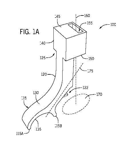
devices have been developed to
aid in eye drop delivery, and they each have their own set of issues on drop
delivery. For example, those
devices that rest on the tissue around the eye make it difficult to hold the
eye lid open to insure the drop gets
into the eye, and there is a natural tendency to close the eye when it is
covered.
[0004] Current devices that aid in the application of a liquid drop to a
ROI also lack the ability to
conform to the specific needs of the user. There is an unfulfilled need for an
operational device-based
platform that facilitates the successful delivery of liquid drops to the ROI
based on the specific need of an
individual user, where the need of the individual user may change over time.
1
CA 03034001 2019-02-14
WO 2018/044758 PCT/US2017/048819
SUMMARY
[0005] An embodiment of the present invention provides a set of devices
configured to retain a
dispenser of liquid. As used herein, and unless expressly defined otherwise,
the terms "set", "kit", "array"
where applied to devices are intended to define and cover one or more devices.
A device in the set includes a
base with a top side and a bottom side (the base having first and second base
ends); an arm extending from
the top side of the base at a first end of the arm; and a holder portion with
a bore formed through the holder
portion and having a bore axis, the bore sized to removably retain an end of
the dispenser. The holder portion
is affixed to a second end of the arm to define a target region for drops
emitted from a tip of the dispenser
(when the dispenser is retained in the bore) in a first plane parallel to a
plane that passes through the first and
second base ends, the target being substantially centered at the bore axis.
The device may optionally contain a
unit that includes an optical system with a field-of-view (FOV). Such unit is
cooperated with the arm to
orient the FOV to cover the tip and the target region (when the dispenser is
retained in the bore) to dispense
the liquid towards the target region. In one embodiment, the base is arcuately
shaped and dimensioned to fit
above and in contact with a user's nose bridge; the bore axis passes through
an eye of the user when the base
is positioned on the user's nose bridge; and/or the bore has a cross-section
(in a plane transverse to the bore
axis) which is one of (i) a rectangular cross-section and (ii) as a cross-
section in which the bore defines a
curve having a radius of curvature (in one embodiment - a constant radius of
curvature). Alternatively or in
addition, at least one of a length of the arm and an inclination of the arm
with respect to the base is adjustable
to position the bore axis to pass through a user's eye once the base is
positioned on a user's nose bridge. The
device may further comprise a wing portion affixed to the arm at a point
between holding portion and the
base and extending from the arm along an axis that is transverse to a
reference plane, which reference plane
contains the bore axis and passes through the arm. In a specific embodiment,
the base may be curved in a
plane containing the bore axis, while a cross-section of the bore defined in a
plane perpendicular to the fore
axis has one of (i) a curvature in a plane perpendicular to the bore axis, and
(ii) a closed perimeter.
[0006] Embodiments also provide a set of devices configured to retain a
dispenser of liquid, the set
comprising: an active device and a passive device. Each of these active and
passive devices includes: (i) a
base with a top side and a bottom side, the base having first and second base
ends; (ii) a holder body having
first and second sides and an opening formed therethrough along a first axis
from the first side to the second
side, the opening being sized to retain the dispenser having a nozzle; and
(iii) an arm elongated along a
second axis that is inclined with respect to the first axis, the arm having a
first end affixed to the holder body
and a second end affixed to the base. Each of the active and passive devices
is dimensioned such that (when
the dispenser is retained in the opening with the nozzle directed along the
first axis and away from the holder
body) a target region for delivery of a drop of the liquid contained in the
dispenser is defined in a first plane
2
CA 03034001 2019-02-14
WO 2018/044758 PCT/US2017/048819
that is parallel to a plane passing through the first and second base ends,
the target region being substantially
centered at the first axis. In contradistinction with the passive device from
the set, the active device
additionally includes, at its arm, a data-recording unit containing an optical
system with a field-of-view
(FOV) defined to cover and include (a) a tip of the nozzle, when the dispenser
is retained at the opening, and
(b) the target region. Alternatively or in addition, and for every device in
the set: the base may be arcuately
shaped and dimensioned to fit above and in contact with a user's nose bridge;
the device may be dimensioned
such that, when the base is on a user's nose bridge, the first passes through
an eye of the user when; and the
opening may have a cross-section in a plane transverse to the first axis, the
cross-section being one of (i) a
rectangular cross-section and (ii) as a cross-section in which the opening
defines a curve having a constant
radius of curvature. Alternatively or in addition, at least one of a length of
the arm and an inclination of the
arm with respect to the base, in a device from the set, is adjustable to
position the first axis to pass through a
user's eye once the base is disposed on a user's nose bridge. In a particular
embodiment, at least one device in
the set includes a wing portion affixed to the am) at a point between the
holding body and the base and
extending from the am) along an axis that is transverse to a reference plane,
the reference plane containing the
first and second axes. In one embodiment, and for each device in the set, the
base is curved in a plane
containing the first axis and a cross-section of the opening defined in a
plane perpendicular to the first axis
has one of (i) a curvature in a plane perpendicular to the bore axis, and (ii)
a closed perimeter. In a specific
implementation of the set, a structural configuration of the active device and
a structural configuration of the
passive delivery device are substantially the same with an exception of the
data-recording unit present at the
arm of the active device. In a related embodiment, the active device may
include one or more of (i) a
programmable computer-readable processor in operable cooperation with tangible
non-transient storage
medium, the processor configured to acquire optical data that have been
collected by the data-recording unit
and that represent a scene at the target region; and (ii) a sensor system
configured to wirelessly communicate
with a programmable electronic circuitry to produce a record of time schedule
of actual use of the active
device, that has been equipped with the dispenser, for drop delivery into the
target region. In one
implementation, an optical axis of the optical system intersects the first
axis at the target region and,
optionally, it intersects the first axis at an acute angle (the acute angle
being an internal angle of a triangle
defined by the first axis, second axis, and optical axes). The holding body
may be shaped as a cuboid.
Alternatively or in addition, for each device in a set the bottom side is
curved with a center of curvature
located in a plane containing both the first and second axes, the center of
curvature being separated from the
first end by a distance exceeding a length of the ann.
[0007] A related embodiment provides a method for using a set of devices
configured to retain a
dispenser of liquid. The set of devices includes an active device and a
passive device, wherein each of the
3
CA 03034001 2019-02-14
WO 2018/044758 PCT/US2017/048819
active and passive devices contains (a) a base having a top side, a bottom
side, and first and second base ends;
(b) an arm extending from the top side of the base at a first end of the arm;
(c) a holder portion with an
opening therethrough, the opening having an opening axis and sized to retain a
liquid drop container having a
nozzle, (here, the holder portion is affixed to a second end of the arm such
that when a corresponding device
is in operational position with the liquid drop container retained at the
opening, a target region for delivery of
drops emitted from the nozzle is defined in a first plane that is parallel to
a plane passing through the first and
second base ends, the target region being substantially centered at the
opening axis). In comparison with and
in contradistinction to the passive device in a set, the active device
additionally includes, at its arm, a data-
recording unit containing 1) an optical system with a field-of-view (FOV)
defined to cover and include (i) a
tip of the nozzle of the container retained in the bore, (ii) the target
region, and (iii) a space separating the tip
from the target region, and 2) an optical detector. Here, the data-recording
unit is configured to record
images of a scene within the FOV. The method includes the steps of: applying
hand input to the active
device to emit a liquid drop from the container retained by the active device
in a direction of the target region
while recording a series of image frames, each frame representing a
corresponding position of the drop in the
space; monitoring, with the use of the data-recording unit, whether the drop
landed in, partially in, or out of
the target region; and using the passive device to deliver a liquid drop from
the container retained therein to
the target region. In one implementation, the use is made of a device (in the
set) for which a third plane
tangential to a point at the top side and the second plane are parallel to one
another. The step of using may
include i) applying hand input to the passive device to emit a liquid drop
from the liquid drop container
retained in by the passive device in the direction and/or ii) starting to use
the passive device to deliver the
liquid drop from the container retained therein when results of the monitoring
indicate successful and
repeatable delivery of the drop to the target region.
[0008] In a specific embodiment of the method, at least one of the
following conditions is satisfied:
(i) one or more of the applying, and using includes self-administering of the
drop by the user without
supervision; (ii) the monitoring includes wirelessly monitoring via a remote
unit; and (iii) any of the applying
and using includes compressing the liquid container, that has been retained at
the opening, against a lateral
protrusion located between the holder portion and the base with one of (a) a
finger, and (b) a level portion of
the device hingedly attached to the holder portion while the base is
positioned on a nose bridge of a user with
the bottom side in contact with the nose bridge, and wherein the target region
is the user's eye. In one
implementation, each of the applying and monitoring is carried out after the
using. The method may
additionally include one or more of the following steps: (i) adjusting one or
more of a position of the active
device, an orientation of the active device, and the hand input based on
results of the monitoring; and (ii)
inserting the liquid drop container in the opening of the holder portion to
retain the container along the
4
CA 03034001 2019-02-14
WO 2018/044758 PCT/US2017/048819
opening axis with the nozzle pointing towards the target region. The step of
inserting may include one of the
following: (i) retaining a flat tail portion of a single-use squeezable liquid
drop container in said opening, the
opening defining a hollow through the holder portion, the opening axis being
completely surrounded by the
holder portion in a cross-section that is transverse to the opening axis; and
(ii) retaining a cylindrical neck of
a multiple-use squeezable liquid drop container in said opening, wherein the
opening is formed between first
and second prongs of the holder portion, the first and second prongs extending
transversely to the arm. In a
specific implementation of the method, at least one of the top side and the
art includes indicia of location, and
any of the retaining the flat tail portion and retaining the cylindrical neck
includes positioning a tip of the
nozzle substantially at a level of said indicia of location. Alternatively or
in addition, the embodiment of the
method may comprise one or more of: (i) positioning any of the active and
passive device on a nose bridge of
a user while bringing a cross-stabilizer portion of the device in contact with
a forehead of the user, wherein
the cross-stabilizer portion extends transversely from the art between the
holder portion and the base; and (ii)
with a programmable electronic circuitry, generating a user-perceivable report
containing data that represent
whether the drop landed in, partially in, or out of the target region, and
further complemented with
determining if a change of employing the active device to employing the
passive device is appropriate (based
at least in part on a figure of merit calculated from said data and
representing success of a drop delivery to the
target region the report).
BRIEF DESCRIPTION OF THE DRAWINGS
[0009] The invention will be more fully understood by referring to the
following Detailed Description
of Specific Embodiments in conjunction with the not-to scale Drawings, of
which:
[0010] Figs. 1A, 1B illustrate, in perspective and top views
respectively, a passive device structured
to accommodate a single-use container of liquid according to an embodiment of
the invention;
[0011] Figs. 2A, 2B show the passive device of Figs. 1A, 1B employed to
retain a single-use liquid
drop dispenser in a dispenser-accommodating opening of the device;
[0012] Figs. 3A provide perspective views of a passive device according
to a related embodiment of
the invention; Fig. 3A: full device; Fig. 3B: a pitch-fork (bottle-holding)
portion of the device;
[0013] Figs. 4A, 4B, 4C illustrate a mechanism of retaining a multi-use
liquid drop dispenser (or
bottle, or container) in the device of Fig. 3 Fig. 4A: a process of insertion
of the drop dispenser between the
prongs of a pitchfork portion of the device; Fig. 4B: two multi-use liquid
drop dispensers of different
dimensions, one being kept! retained by the device of Fig. 3; Fig. 4C is a
schematic diagram illustrating an
example of the passive device of Fig. 3 dimensioned to accommodate and retain
one of the dispensers of Fig.
4B;
CA 03034001 2019-02-14
WO 2018/044758 PCT/US2017/048819
[0014] Fig. 5 illustrates the use of the passive device of Fig. 3 for
dispensing of liquid drops from the
container retained in the device;
[0015] Figs. 6A, 6B are perspective and side views, respectively, of a
passive liquid-drop-dispenser
holding device configured according to another embodiment of the invention;
[0016] Figs. 7A, 7B are perspective and side views of an active dispenser-
holding device structured
according to an embodiment of the invention;
[0017] Figs. 8A, 8B illustrate perspective and front views of an active
device configured according
to another embodiment of the invention;
[0018] Fig. 8C illustrates the device of Fig. 8A with a fluid container
retained between the prongs of
the pitchfork of the device;
[0019] Figs. 9A, and 9B illustrate, in perspective and top views, a body
of a specific embodiment of
a passive device structured to accommodate a single-use container of liquid;
[0020] Figs. 9C and 9D provide perspective and bottom views of a lever-
portion of the specific
embodiment that mechanically cooperates with the body shown in Figs. 9A, 9B;
[0021] Fig. 10 illustrates the specific embodiment formed by mechanical
cooperation of the body of
Figs. 9A, 9B and the lever of Figs. 9C, 9D, and with a single-use container
retained in the slit of the
embodiment;
[0022] Figs. 11A, 11B, and 11C provide perspective, bottom, and side
views, respectively, of a
passive device structured to accommodate a single-use container of liquid
according to an embodiment of the
invention;
[0023] Fig. 11D illustrates the embodiment of Fig. 11A with a single-use
fluid container retained in
the bore of the embodiment and pressed against the tongue protrusions, located
on the extension of the body of
the device;
[0024] Figs. 12A, 12B, and 12C illustrates a passive device structured to
accommodate a single-use
container of liquid according to an embodiment of the invention. Fig. 12A:
perspective view; Fig. 12B: top
view; Fig. 12C side view;
[0025] Figs. 13A, 13B are perspective and top views of an embodiment of a
passive device structured
to accommodate a multi-use container of liquid between the prongs of a
pitchfork portion of the device which
also features cross stabilizers;
[0026] Fig. 14 is an illustration of a plurality of single-use
containers, accommodation of which is
provided by a plurality of embodiments of the invention;
[0027] Fig. 15 is an active device structured to accommodate multi-use
containers of liquid according
to an embodiment of the invention;
6
CA 03034001 2019-02-14
WO 2018/044758 PCT/US2017/048819
[0028] Figs. 16A, 16B, 16C, and 16D provide side and top and perspective
views of a passive device
structured to accommodate a single-use container of liquid according to an
embodiment of the invention, and
the associated steps of inserting a single-use container of liquid into the
device;
[0029] Fig. 17 includes 4 (four) frames and illustrates an EDAM device
(A), highlight of the proper
eye drop application (B), an eye drop tip contacting eyelid and cornea (C),
and multiple missed drop application
(D);
[0030] Fig. 18 contains a table summarizing demographics of empirical
study subjects;
[0031] Figs. 19A, 19B are plots providing empirical comparison between
the results of actual drop
delivery to an eye vs. prescribed regimen. The overall percent actual
treatment is not significant when compared
with the perceived with actual (Fig. 19A). The percent absolute variation from
the prescribed regimen (Fig.
19B) yields significant difference of perceived vs actual (p <0.001). Error
bars represent standard deviation;
NS implies (not significant);
[0032] Figs. 20A, 20B are plots providing results of an "intention to
treat": a comparison between
intention to deliver drops to an eye and the prescribed regimen. The overall
percent intention to treat is not
significant when comparing the perceived to actual (Fig. 20A). The percent
absolute variation from the
prescribed regimen between the two groups is highly significant (P < 0.001).
Error bars represent standard
deviation; NS implies (not significant);
[0033] Figs. 21A, 21B are plots providing information about the overall
percent success rate (drops
in / drops dispensed) and the percent absolute variation from the prescribed
regimen of the study population is
significant (p < 0.007) when comparing the perceived with the actual. Error
bars represent standard deviation;
[0034] Fig. 22 includes a table summarizing missed applications of
droplets to an eye and occurrences
of the contamination of a drop dispenser;
[0035] Figs. 23A, 23B, 23C, and 23D illustrate an alternative embodiment
of the invention;
Relative scales of elements in Drawings may be set to be different from actual
ones to appropriately
facilitate simplicity, clarity, and understanding of the Drawings. For the
same reason, not all elements present
in one Drawing may necessarily be shown in another.
DETAILED DESCRIPTION
[0036] In accordance with preferred embodiments of the present invention,
methods and apparatus
are disclosed for solving the operational shortcomings of current devices and
methodologies employed to aid
in the delivery of a liquid drop to a region of interest (ROI). In particular,
a shortcoming of current liquid
drop-dispensing devices is their inability to conform to the specific needs of
a particular user. This
shortcoming is addressed by providing an operationally-adjustable device and a
plurality of such devices, as a
7
CA 03034001 2019-02-14
WO 2018/044758 PCT/US2017/048819
kit, that can be fit to a user's unique needs based on the user's anatomy
(e.g., high nose bridge versus a low
nose bridge) and/or any other physical traits of the user (e.g., tremors,
arthritis, etc.), as well as the type of the
used liquid container (e.g., single-use, multi-use, length, etc.).
[0037] Another shortcoming of current devices and methods employed to aid
in the delivery of a
liquid drop to a region of interest is the lack of means to evaluate and
teach/train the user the correct way to
effectively deliver a liquid drop to the ROT, specifically when the user is
primarily attempting to deliver the
drops in his/her at-home environment and without supervision. (Such situation
is explained in detail in the
accompanying Appendix, which provides the results of several clinical studies
investigating this problem.)
This shortcoming is addressed by providing two or more liquid drop delivery
devices (configured to hold and
retain liquid dispensers or drop dispensers such as containers of fluid),
where at least one device is "active"
(in that it has an event registration/feedback system such as an optical
system or a sensor system, for
example, configured to collect data and provide feedback about whether a drop
is successfully delivered to
the ROT or indicating whether and when the device is being used), and at least
one other device is "passive"
(in that, optionally being otherwise substantially structurally similar in
configuration and operation to the
"active" device, it does not have such a feedback system and is configured to
simply hold, stabilize, and/or
position a liquid-drop container to aid in successful delivery of the liquid
drop(s).
[0038] An additional structural feature employed in an active device may
be a feedback-generation
capable system that is configured to monitor the process of delivery of the
liquid drop, and/or to collect data
regarding the user's delivery, or attempted delivery, of the drop to the ROT.
The method for use of the array
of devices includes operational transitioning between active and passive
devices depending on the user's
needs. If the user has not mastered the intended delivery technique, an active
device can be used to monitor
and track the drop delivery data. Depending on the feedback data, adjustments
can be made to the user's
delivery technique. For example, once the actively collected data indicate
that drop delivery is successfully
occurring as intended (either spatially, with respect to the targeted ROT, or
temporally, in terms of the
delivery on schedule, or both), the user can transition to using a passive
device. Accordingly, the process of
using the platform or set or kit of devices includes a user's transitioning
from employing the active device to
employing the passive device (once the data collected by the feedback system
indicate that the user's drop-
delivery-to-the-ROT technique is successful). In a related example, if the
user has other specific needs (for
example, they user forgets to deliver the liquid at the appropriate times), an
active device used at the time can
be additionally equipped with a sensor system that can be paired with a
smartphone or other wireless
application, which is programmed to remind the user to use the liquid drops if
and/or when the device is not
used at the appropriate times. Alternatively, the process of using the set may
include the user's transitioning
8
CA 03034001 2019-02-14
WO 2018/044758 PCT/US2017/048819
from employing the passive device to employing the active device (once the
collection of feedback data is
prompted by lack of success of using the "passive" device on the user's part,
to begin with).
[0039] Yet another shortcoming of current devices is the problem caused
by the inability of existing
liquid-drop-delivery aids and monitoring systems to accommodate single-use
containers and/or dispensers of
liquid (to which related industry is transitioning). This deficiency is solved
by providing an embodiment of a
device configured to contain a cavity, judiciously sized to retain a single-
use liquid drop dispenser, while the
device also has an optional built-in feedback system (such as an optical means
for continued monitoring of the
liquid drop delivery to the ROT or a sensor system for indicating whether and
when the device is being used).
[0040] While various Figures discussed below show specific embodiments of
either a passive device
or an active device, it is appreciated that all embodiments of the invention
generally have in common several
structural components and/or characteristics, regardless of a particular
configuration, orientation, and/or
dimensions of such components. Preferably, all embodiment are made from
material(s) lending themselves to
injection molding, lathe machining, or 3D printing. Such common components are
now introduced in reference
to Figs. 1A, 2A, 4C A base or foot 115; an arm 120 extending from the base
115; and a holder (or holder
portion) 125 typically connected to the opposite end of the arm 120 are what
may be referred to as the main of
such components. The base 115 typically has a top side 130 and bottom side
135. The bottom side 135 of the
version of the base 115 shown in Fig. lA is shaped to deviate from being
linear - generally, curvilinearly or to
fon an angle, arcuately as shown - to define two ends of the base: the end
115A and the end 115B. Generally,
the curvilinear shape of the base 115 can be part of a round, elliptical, or
parabolic curve, to name just a few.
[0041] The arm 120 extends from the top side 130 of the base 115 and
connects at its other end to
the holder 125. The holder 125 includes a body 140, which has a first surface
145 and a second surface 150
(as shown - upper and lower surfaces of the body 140), and a bore or cavity or
hole or recess or space 155
that is formed through the body 140 and extends from the first surface 145 to
the second surface 150 along a
bore/cavity/hole/recess/space axis 160.
[0042] Generally, the bore 155 can be fully closed on four sides that
circumscribe / surround the
first axis 160, as shown in embodiment 100 of Figs. lA and 2A. Alternatively,
the bore 155 may not be
completely closed on one of the four sides and may have a slit or opening
along a side of the body 140 for
example, along the third side 365 of the body 140 (as is shown later in
embodiments 300, 800 of Figs. 3, 8A,
in which cases the holding body with a bore there through is shaped as a
pitchfork). Alternatively, the bore
155 may also not extend completely through the body 140 and may be dimensioned
as a cavity sized to retain
only an end or a tail of a container of liquid. Stated differently, depending
on a particular implementation of
the device, the bore or cavity 155 can be configured as a hollow throughout
the body 140 (such that the cross-
section of the hollow is circumscribed by the material of the body 140) or as
a cavity with an opening defined
9
CA 03034001 2019-02-14
WO 2018/044758 PCT/US2017/048819
in a direction that is substantially perpendicular to the bore axis 160. Also,
and depending on a particular
implementation, the bore 155 is dimensioned to support a corresponding liquid-
holding container either at the
peripheral or tail portion of the container (shown schematically in Fig. 2A as
an end of the container opposite
to the container's nozzle 285) or at the container's intermediate portion
(such as a neck 440) located between
the nozzle and the opposite end of the container (as shown, for example, in
Fig. 4C). Accordingly, the bore is
characterized by a cross section (defined in a plane transverse to the bore
axis 160) that is substantially
rectangular or that defines a curve with a constant radius of curvature (that
is, the radius of curvature of a wall
of the bore is the same at any point of the wall of the bore). Notably, in
embodiments in which the foot or
base portion is curved and in which the holding portion defines a pitchfork,
based portions and the holding
portion are oriented in planes that are transverse to one another.
Specifically, the pitchfork-like shaped
portion lies in a plane that is perpendicular to the bore axis 160, while the
curvature of the foot portion is
defined in a plane that contains the bore axis 160 (see, for example, radius
of curvature R in Fig. 3).
[0043] When the devices are in their operational position, the holder 125
is oriented above the base
115 and the region of interest (ROT) 170 is located substantially below the
bore 155 (and, optionally, in a
plane that is parallel to the plane passing through the ends 115A, 115B).
[0044] The arm 120 is affixed to the body 140 at the arm's first end and
extends from the body 140
generally along a second axis 175 that is inclined with respect to the first
axis 160. The arm 120 has its other
end affixed to the base 115. When the base 115 has an arcuate shape, the
center of curvature of the arc may be
chosen to lie in a plane that contains both the first axis 160 and the second
axis 175, and such that the center of
curvature is separated from the first end of the arm 120 by a distance
exceeding a length of the arm 120. In
one implementation, where the base 115 is chosen to be shaped as substantially
half-an-ellipse (with 16 mm
minor axis and 20 mm major axis, or, alternatively, a half round with a 20 mm
diameter; with the thickness of
the body of the base 115 is about 2.8 mm, while the width is about 10 mm) the
distance between the axis 160
and the center of the base (nose bridge) 115 is 31 mm, resulting in that the
center of region of interest 170 is at
a separation distance of about 31 mm away from the center of the nose bridge
during the operation of the
device, to address a typical distance between eye-pupils of a typical person
of about 58 mm to about 66 mm.
This separation distance can be customized for patients.
[0045] These general structural features are judiciously chosen to ensure
that both the active and the
passive versions of a particular embodiment are substantially structurally
similar to one another, and can be
used interchangeably by the same user with minimal - if any - deviation from
the established drop-delivery
procedure to which the user became accustomed while using one of the versions
of such device.
CA 03034001 2019-02-14
WO 2018/044758 PCT/US2017/048819
Passive Embodiments and Methods of Operation of Same
[0046] Example 1: Drop-Dispenser for Single-Use Container. .. Referring
now to Figs. 1A, 1B
and 2A, 2B, an embodiment 100 of a passive device structured to accommodate
single-use containers of
liquid that are becoming prevalent in related industry is shown to have a bore
155 with a polygonal (for
example, rectangular) cross-section in a first plane that is transverse to the
first axis (the axis of the bore) 160.
Here, the cross-section of the bore in a plane perpendicular to the axis 160
has a closed perimeter. The bore
155 as shown is defined by bore walls that are substantially parallel to the
first axis 160 and limited by the
upper and lower surfaces 145, 150. The bore 155 is appropriately dimensioned
to tightly hold a single-use
container of liquid 280, a peripheral substantially flat end portion or tail
282 of which is reversibly inserted or
placed into the bore 155 such that the body and the nozzle 285 of the
container are extending alongside the
arm 120, as shown in Fig. 2. When the single-use container 280 is properly
affixed in the bore 155, its nozzle
285 is pointing generally along the arm portion of the device and generally
towards the base and/or the area
neighboring the ROT. In a specific case, the first axis 160 points towards the
ROT 170. The ROT is generally
defined in a plane parallel to the plane that contain both ends 115A, 115B of
the base 115 and substantially
centered at the center axis 160 of the bore 155. The single-use container 280
is generally made of pliable
material such that it can be effectively manipulated to emit a single drop
when squeezed. In operation, once
secured in the bore 155, the single-use container 280 is situated next to the
arm or arm portion 120 such that
the container 280 may be compressed against a side of the arm or arm portion
120.
[0047] Additionally, the single use container device may contain a
marking or reference element
122 (such as a protrusion or indentation or another indicia of location on a
surface of the arm 120) configured
to indicate a level or a point with respect to which (for example, above
which) the tip of nozzle 285 of the
single-use container 280, after opening, should be placed for use in a
particular application (In a non-limiting
and a very specific example, in an application of a drop to the eye, such
marking element serves to reduce
risk of contact of the container 280 with the eye).
[0048] Example 2: Drop-Dispenser for Single-Use Container. According
to the idea of the
invention, various embodiments of passive devices are tailored to specific
needs of a user of the device(s).
For example, the embodiment 900 shown in Figs. 9A, 9B, 9C, and 9D includes the
main portion or body 905
with already-described above, main components (such as base 115, arm 120, and
holder portion 125), but in
addition incorporating a separate, removably integrated with the main portion
905 of the embodiment
component 910 (referred to, for simplicity, as cover or lever) to facilitate
the squeezing of the single-use
container 280 once the container is installed and retained in the bore 915 of
the holder 125 (as shown in Fig.
11
CA 03034001 2019-02-14
WO 2018/044758 PCT/US2017/048819
10). A lever 910, which is shown as a stand-alone, disconnected from the body
905 element in Figs. 9C, 9D,
is configured to be attached to the body 905 of the embodiment 900 via co-
axial protrusions 920 (that extend
towards one another from the facing-each-other surfaces of the lever 910) and
that are, when assembled with
the body 905, accepted into receptacles/apertures 925 formed on opposite sides
of the holder portion 140 of
the body 905. When assembled with the body 905 as shown in Fig. 10, the lever
910 is connected to the
body in such a manner as to make the protrusions 920 and receptacles 925
substantially co-axial with each
other and to allow the lever 920 to freely pivot about the axis that is common
to the protrusions 910 and the
receptacles 925 and that extends through the centers of the receptacles 925.
This lever 910, when assembled
with the body 905 to form the embodiment 900, makes it easier for a user to
compress an inserted/retained
single-use container 280 by providing a greater surface area with which to
apply pressure. When the user
applies pressure to the lever 910 in a direction towards the retained
container 280, the single-use container
280 is pressed against protrusion or tongue 930, which further aides in
helping the user to effectively emit the
desired number of drops from the container 280.
[0049] The foot or base 115 is shown equipped with a shelf or protrusion
935 (which, in the
alternative implementation can also be formatted as an indentation or another
indicia on a surface of the foot
or base 115), and configured to indicate a level or a point with respect to
which (for example, above which)
the tip of nozzle 285 of the single-use container 280, after opening, should
be placed for use in a particular
application (in a non-limiting and a very specific example, in an application
of a drop to the eye, such
marking element serves to reduce risk of contact of the container 280 with the
eye). In other words, the
element 935 is configured to assist with proper positioning of the drop bottle
tip when such bottle is retained
in the embodiment of the drop dispenser.
[0050] Example 3: Drop-Dispenser for Single-Use Container.
The embodiment 1100 shown in
Figs. 11A, 11B, 11C is similar to that of the embodiment of Fig.9A, 9B, 9C,
however, it does not include and
operates without the use of the lever (such as lever 910 of Fig. 10). In
addition to the main components (such
as base 115, arm 120, and holder 125), this embodiment may include an
extension 1105 protruding
downwardly from the holder portion 125 (and extending generally in the same
direction in which the arm 120
extends from the holder portion 125), equipped with tongues 1110 on its front
surface (the surface facing
away from the arm 120). As shown, the extension 1105 and the arm 120
mechanically cooperate such as to
define a continuous surface 1115, shown in Figs. 11A, 11C as an arcuate
surface. In the process of use of the
embodiment 1100, the user's thumb may be positioned in the arcuate gap formed
between the arm 120 and
the extension 1115, as illustrated in Fig. 11D, thus providing the user with
an effective holding position. Fig.
11D shows embodiment 1100 retaining a single-use container of liquid 280 at
its peripheral portion 282.
12
CA 03034001 2019-02-14
WO 2018/044758 PCT/US2017/048819
[0051] The tongues 1110 aid in causing a single-use container 280 (once
inserted and retained in the
bore 1120) to emit the desired amount of fluid (for example, a pre-determined
number of drops) when
squeezed or pressed against the tongues 1110. The multiplicity of tongues 1110
- as opposed to a single, only
tongue - allows, in operation of the device with different single-use
containers, for compression of
differently-shaped single-use containers (the outer surface of some of which
may be concave, as that in Fig.
11D, while the outer surface of others may be convex in shape). Similar to the
embodiment shown in Fig. 10,
the foot or base 115 may be equipped with a shelf or protrusion 1125 (which,
in a related embodiment can
also be configured as an indentation or another type of indicia on a surface
of the foot or base 115), and
configured to indicate a level, or a point with respect to which (for example,
above which) the tip of nozzle
285 of the single-use container 280, after opening, should be placed for use
in a particular application. The
feature 1125, generally, is employed to properly position the tip of the
liquid container (when retained in the
device 1100, such that the tip is no lower than the level of the feature 1125.
[0052] Example 4: Drop-Dispenser for Single-Use Container.
The embodiment 1200, shown in
Figs. 12A, 12B, and 12C, also a passive device structured to accommodate
single-use containers of liquid,
includes the main components (base 115, arm 120, and holder 125) but with the
a bore or slit 1205 having a
cross-shaped cross-section in a first plane that is transverse to the axis of
the bore 1205. The bore 1205 as
shown is defined by bore walls that are substantially parallel to the axis of
the bore 1205 and limited by the
upper and lower surfaces 145, 150. The bore 1205 is appropriately dimensioned
to tightly hold a single-use
container of liquid 280 in two positions, where each position is angled at
forty-five degrees with respect to
plane 1215 defined by a central vertical cross-section of device 1200, as
shown in Fig. 12B. This angled
position of the single-use container 280 aids the user in effectively pinching
and squeezing the container
while also manipulating the device 1200. The two positions allow the user to
switch the device 1200 in the
opposite direction and accordingly switch the angle of the container.
Similarly to the previously described
embodiments, the foot or base 115 may be equipped with a shelf or protrusion
1210 which can also be an
indentation or another indicia on a surface of the foot or base 115, and
configured to indicate a level, or a
point with respect to which (for example, above which) the tip of nozzle 285
of the single-use container 280,
after opening, should be placed for use in a particular application.
[0053] Example 5: Single-Use Containers of Fluid.
Referring to Fig. 14, various examples of
single-use containers of liquid 280, available commercially, are shown.
Containers of different brands may
have differing lengths (defined by a longitudinal extent of a given single-use
container from the drop
dispensing tip of the nozzle 285 to the opposite end of the liquid holding
portion of the container 1405, and
13
CA 03034001 2019-02-14
WO 2018/044758 PCT/US2017/048819
most commonly adhering to one of two accepted standards of 26 mm and 35 mm. In
terms of shapes, the
most prevalent designs include a trench or slit-like indentation in a body of
the container (shown as t 1410) is
formed between the liquid holding portion or volume 1405 and the peripheral or
tail portion 282 of a given
container. The previously described embodiments related to holding a single-
use container of liquid 280 are
designed to hold and retain a peripheral/tail portion 282. A related
embodiment of the holder of a single-use
container of fluid, shown in Figs. 16A, 16B, 16C, and 16D is designed to hold
the single-use container of
liquid 280 at the slit 1410 (which, as shown in Fig. 14, may be linearly or
curvilinearly shaped). In order to
accommodate containers of varying lengths, the device illustrated in Figs.
16A, 16B, 16C is provided in at
least two incarnations each having a respectively-corresponding height, which
is generally attained by
modifying the length and angular orientation of the arm 120 with respect to
the foot portion 115. Similarly,
the embodiment described in Figs. 16A, 16B, 16C is also provided in formats
that can accommodate both a
line slit and a curved slit type indentation of a single-use container. In
particular, Figs. 16A, 16B, 16C
provide side and top views of a related embodiment 1600 of a passive device
structured to accommodate a
single-use container of liquid. Figs, 16A, 16B, 16C also illustrate associated
steps for inserting a single-use
container of liquid into the device 1600. Each of Figs. 16A, 16B, 16C includes
two sub-illustrations (shown
embraced with a bracket in a corresponding Figure). The device 1600 includes
the main components (base
115, arm 120, and holder 125); however the holder 125 defines an opening or
bore 1620 on a side of the
holder 125 to form the holder 125 in a shape of a tuning fork. Unlike the
previous embodiments structured to
accommodate a single-use container of liquid, the bore 1620 does not have
walls that are substantially
parallel to the axis of the bore, rather, there is a narrowing towards the
bottom of the bore 1620 that correlates
with the slit 1410 present on the various single-use containers of liquid.
This narrowing of bore 1620 allows
the tight positioning of slit 1410 of the single-use container of liquid 280
as shown in Figs. 16B, 16C. Fig.
16B shows the single-use container of liquid 280 partially inserted into the
device 1600, while Fig. 16C
shows the single-use container of liquid 280 in the fully inserted position.
Stated differently, a single-use
container of liquid 280 can be slid into the holder 125 of the device 1600,
and the narrowed portions of bore
1620 fitted snugly within the slit 1410, while the un-narrowed portions of
bore 1620 securely hold the
peripheral portion 282. A small hole 1630 is provided to allow the user to
mark the middle position of the
single-use container of liquid 280 because the width 1420 of the various
single-use containers varies with the
different brands.
[0054] Example 6: Drop Dispenser for Multi-Use Container. Referring to
Figs. 3A, 3B, 4A,
4B, 4C, and 5, a related embodiment 300 of a passive device structured to
accommodate multi-use containers
of liquid has a bore 155 with a substantially cylindrical cross-section in a
first plane that is transverse to the
14
CA 03034001 2019-02-14
WO 2018/044758 PCT/US2017/048819
first axis 160, where the body 140 further defines an opening at a third side
165 of the bore 155. Stated
differently, the bore 155 in these embodiments defines the space between the
prongs 355A, 355B of the
pitchfork portion of the embodiment 300. Such semi-opened on the side bore
(and/or pitchfork portion itself)
is dimensioned to hold a multi-use container of liquid 490, the neck 440 of
which is inserted or placed in the
bore 155 through the opening on the side 365, as shown in Figs. 3A, 3B, 4A,
4B, 4C and 5. Comparison
between the implementations of the bore or cavity 155 shown in Figs, 3A and 3B
illustrates that the surface
defining the cavity may contain angles and/or may be fully differentiable and
smooth. (Generally, in
embodiments the holder 125 of which is substantially similar to that of Figs.
3A, 3B, For all devices having
355A and 355B, The thicknesses of the prongs 355A, 355B are about 4 mm. inner
circle formed by the cavity
155 and embraced by the prongs 355A and 355B is about 14 mm in diameter; the
opening/edge separation
365 between the ends of the prongs 355A and 355B is about 12 mm. These
specific dimensions can be, of
course, customized for specifically-shaped liquid containers.)
[0055] Example 7: Multi-Use Containers. Referring to Figs. 4B and 4C,
two examples of
multi-use containers of liquid 490A, 490B are shown. For purposes of the
device design, one measurement
of conceal is the length of the tip 450 of the bottle 490 which is defined as
the linear distance between the
neck 440 of the bottle and the nozzle 460 which emits the drop, as shown in
Fig. 4C. Generally, the length of
the tip s50 of various multi-use containers differ, with most prevalent
(adhered to in industry) lengths being
either 26 mm or 20 mm. In reference to Fig. 5, when verifying empirically the
practicality of an embodiment
of the dispenser holder, it was determined that if the space or separation
between the tip of the nozzle and
ROT 170 is too small, the tip may be inadvertently brought in contact with the
ROT 170 or surrounding areas
(which could result in contamination of the tip or discomfort for the user).
Alternatively, if the space is too
great, the success rate of delivery of the drop to the ROT is decreased. Based
on clinical testing, the optimal
distance 492 between the tip of the nozzle of the bottle (container) retained
in the holder and the ROT 170 was
found to be about 10 mm. The optimal range, of course, can vary in different
embodiments depending on a
patient's application technique and other physical impediments such as
arthritis, spinal fusion, a tremor or
other physical difficulties. For example, if a patient is having difficulty
successfully delivering to the desired
ROT - a shorter space distance may be helpful. In a different example, if the
tip of the eye drop bottle is
contacting the eye lashes (when the device is in contact with the bridge of
the nose), for example if the eye
lashes are very long, a longer distance 492 might help to reduce the
possibility that the tip of the nozzle will
contact the lids and the resulting contamination and/or blinking the contact
often causes. (Blinking at the
wrong time can interfere with successful drop delivery to the ROT.) Variations
in length for these reasons can
occur of up to or around 6 mm shorter or longer. Accordingly, the dimensions
of a passive device 300 have
CA 03034001 2019-02-14
WO 2018/044758 PCT/US2017/048819
been configured to allow for retaining of differently sized fluid dispensers
while, at the same time, providing
for approximately optimal separation between the tip of the nozzle and the
ROT. For example, in one
embodiment a height 420 of 40 mm used in conjunction with a bottle with a tip
length of 26 mm results in an
approximate distance of 10 mm to the ROT 170, as illustrated in Fig. 4C.
Similarly, an overall height of
device 300 of about 34 mm provides the preferred optimal distance when used
with a bottle with a 20 mm
long tip. The exact distance between the tip of the nozzle 460 and the ROT 170
(for example, an eye) will
vary slightly in practice, depending on specific and different facial features
of a user of the system. For
example, it may be preferred that systems/embodiments employed by a user
having a low nose bridge (such
as a user of Asian descent) are structured and/or dimensioned to provide for a
tip-to-ROT separation that is
slightly shorter than 10 mm, while a user having a higher nose bridge (such as
a user with Northern European
lineage) might be better served with a differently-dimensioned embodiment
providing a tip-to-ROT space that
is slightly larger than 10 mm. In other words, the variability of the facial
features of different users should be
taken into account when structuring a particular embodiment of the invention.
[0056] Example 8: Drop Dispenser for Multi-Use Container.
Referring to Figs. 6A and 6B, a
related embodiment 600 of a passive device (structured to accommodate multi-
use containers of liquid) has a
bore or cavity 155 that defines the space between the prongs 355A, 355B of the
pitchfork portion 610 of the
embodiment 600. Similar to embodiment 300, such semi-opened on the side bore
or cavity (and/or pitchfork
portion itself) is dimensioned to hold a multi-use container of liquid 490,
the neck 440 of which is inserted or
placed in the bore 155 through the opening on the side 365. In a specific
case, the embodiment 600 may have
an optional bottle/container-securing mechanism 695. A portion of the
mechanism 695 is a platform 650, a
position of which is adjustable along the axis 160 to accommodate and retain
multi-use containers of different
sizes, as shown in Fig. 6. In one implementation, the optional securing
mechanism 695 is spring-loaded (with
respect to the upper portion 654 of the body 140) to have its position biased
towards the location of the body
140. (The spring loading arrangement is not shown in Fig. 6, but it may be
disposed in a hollow 654A of the
portion 654, for example.) Once the bottle 490 is loaded between the platform
650 and the pitchfork. As a
result of the spring-loading, the platform 650 forms a vectored-force 658
applied to the bottle 490 in the
direction from the platform 650 towards the pitchfork 610 (which effectively
squeezes and retains a multi-use
bottle 490 in the correct position with its neck 440 cradled between the
prongs 355A, 355B of the pitchfork
portion 610). Additional features of this or any of the devices described may
include a light or multiple light
sources, such as LED or bulbs, to help users to position the device properly,
particularly those users with poor
vision. Such light(s) may aid in imaging of the application, and be used in
combination with a recording
16
CA 03034001 2019-02-14
WO 2018/044758 PCT/US2017/048819
system, which is more fully described below. The devices may also include
mechanical stabilizers, to help
those users with tremors, also described in greater detail below.
[0057] Example 9: Drop Dispenser for Multi-Use Container. Figs. 13A
and 13B illustrate a
related embodiment 1300 of a passive device, structured to accommodate a multi-
use container of liquid
between the prongs 355A, 355B of a pitchfork portion 1310 of the device 1300
and that also features cross
stabilizers or wing portions 1305A, 1305B. The cross-stabilizers or wing
portions are affixed to the arm to
extend in a direction that is simultaneously transverse to the arm and to a
plane (not shown) passing through
the arm and through the axis of the bore of the holding portion. The cross
stabilizers 1305A, 1305B aid a
user in stabilizing the device 1300 against another surface, such as a portion
of the head (for example,
forehead) of the user. This enables the user to achieve better spatial
orientation of the device 1300 with one
hand while, at the same time, also squeezing the multi-use container of liquid
supported by and retained
between the prongs 355A, 355B, with the same hand. This leaves the user's
other hand available to hold
open the eye to facilitate targeted delivery of the desired amount of fluid
from the container (for example, a
predetermined number of drops). This type of configuration may be beneficial
for user's that have tremors or
other motor control issues that benefit from the additional fixation point.
[0058] The shape, dimensions, angular orientation ¨ generally,
configuration - of the cross
stabilizers in relation to that of the arm 120 may be arranged in various
formats, including, but not limited, to
having only one cross stabilizer (that is, a cross stabilizer on only one side
of the am) 120). It should also be
noted that, generally, any of related embodiments disclosed herein ¨ where
active, passive, or configured for
use with a single-used container(s) of liquid ¨ may be equipped with at least
one of the cross stabilizers
1305A, 1305B.
Active Embodiments and Methods of Operation of Same
[0059] The idea behind complementing an array or kit or set of passive
fluid-dispenser holders with
embodiments of active devices is to enable a user of the kit to at least train
himself to deliver drops of fluid
into his eye(s) based on operational feedback provided by the active device in
terms of optical data
representing circumstances of drop(s) delivery (such as timing, success of
delivery). Alternatively or in
addition, the optical data collected with the active device in an unbiased
fashion (and without human
interference) can be used by the observing clinician for the purposes of
adjusting the type of treatment to be
used (for example drops versus laser or surgery for glaucoma) or the addition
or subtraction of a drop
medication to the patient's treatment regimen or at least one of the dose and
schedule of patient's (user's)
17
CA 03034001 2019-02-14
WO 2018/044758 PCT/US2017/048819
treatment, in an exact and systematic fashion to answer questions relevant to
the success of the patient's
treatment and evaluation of outcomes of such treatment.
[0060] Example 10: Drop Dispenser for Single-Use Container. To this end,
and referring to Figs.
7A, 7B and 8A, 8B, 8C, embodiments of an active device may be substantially
structurally similar in
dimensions and size to their counternart passive devices. Figs. 7A, 7B, for
example, show an embodiment
700 of an active device that is structured to accommodate single-use
containers of liquid and that is
substantially structurally similar to that of the passive device 100 of Figs.
lA and 2A. The active device 700,
however, is additionally equipped with a data-recording and/or processing unit
705 that includes an optical
system 705A, disposed at the arm 120 between its first and second ends. The
optical system 705A has a
field-of -view (FOV) with a FOV axis 710. Such FOV covers a region of interest
(ROT) 170 around a point
on the first axis 160 in a plane transverse to the first axis 160, where the
FOV axis 710 intersects the first axis
160 at the ROT 170. More specifically, as shown, the FOV axis 710 intersects
the first axis 160 at an acute
angle a, where the acute angle a is an internal angle of a triangle defined by
the first axis 160, the second axis
175, and the FOV axis 710. By analogy with the embodiment 100, the element 122
(as shown - a shelf or
protrusion from the body of the processing unit 705 represents the optional
indicia of location, which in
operation of the device signifies the level at which the tip of the nozzle of
the used liquid container should be
positioned when the container is retained in the device.
[0061] Example 11: Drop Dispenser for Single-Use Container. Figs. 8A, 8B,
and 8C show an
active device 800 structured to accommodate multi-use containers of liquid,
which is substantially structurally
similar to the passive device 600 shown in Figs. 6A and 6B. Similar to the
active device structured to
accommodate single-use containers of liquid, the active device 800 is equipped
with an active unit 805
including an optical system 805A, disposed at the arm 120 between its first
and second ends. The optical
system 805A has a field-of -view (FOV) with a FOV axis 710, the FOV covering a
region of interest (ROT)
170 around a point on the first axis 160 in a plane transverse to the first
axis 160, and where the FOV axis 710
intersects the first axis 160 at the ROT 170. More specifically, the FOV axis
710 intersects the first axis 160 at
an acute angle a, where the acute angle a is an internal angle of a triangle
defined by the first axis 160, the
second axis 175, and the FOV axis 710.
[0062] Depending on the specifics of use, each previously described
embodiment of a passive device
may be appropriately modified to be transformed into or formatted as an active
device. For example, referring
to Fig. 15, an active device embodiment 1500 structured to accommodate multi-
use containers of liquid is
18
CA 03034001 2019-02-14
WO 2018/044758 PCT/US2017/048819
configured substantially structurally similar to the embodiment 300 of the
passive device shown in Figs. 3, 4A,
4B, 4C, and 5.
[0063] Generally, the active unit of a given embodiment (such as the
active units 705, 805) and an
optical system 705A, 805A of such unit can be configured substantially
equivalently for both an active device
structured to accommodate single-use containers of liquid and an active device
structured to accommodate
multi-use containers of liquid. In related embodiments, the active units can
be connected, via electrically-
conducting members or otherwise, to a local or remote programmable processor,
which is in operable
cooperation with tangible non-transient storage medium. The processor in such
case is configured to acquire
optical data collected by the optical system 705 representing an image of a
scene present at a given time at the
ROT 170. These data can then be analyzed to determine if a liquid drop
expelled from the nozzle (285 of the
single-use container, or 460 of the multi-use container, affixed in the body
140 is successfully delivered to the
ROT 170).
[0064] Alternatively or in addition, the optical system 705A, 805A could
be augmented with a sensor
system that contains a communications function. This sensor system could be
disposed in a housing of the
active unit 705, 805 and/or paired with a computer-based application to
perform various functions. This
computer-based application could, for example, be downloaded onto a smartphone
or similar device. The
sensor system could communicate with the application to indicate at which
times the active device is being
employed. If the active device is not being employed according to the
specified scheduled, the application
would alert the user via their smartphone to use the device to administer the
missed drops after a scheduled
administration is not sensed.
[0065] If a particular user's specific needs so demand, each of the
embodiments described herein may
be structurally adjusted to fit such specific needs. This adjustability may be
embodied in the device itself (for
example, at least one of the length of the arm 120 and the angle of the arm
120 with respect the foot or base
115, may be adjustable, via an appropriate telescopic mechanism and/or hinge).
[0066] Alternatively, or additionally, the customization of a specific
embodiment may be achieved
by fitting differently-sized devices to the particular user to determine which
suits the needs of the user most
effectively. Such fitting could be performed in a number of different ways,
for example, it could be
accomplished through input of the parameters of a particular liquid container
being used into a database
(which, with the use of a programmable processor would match the container,
based on its dimension, to the
most appropriate embodiment of the device). The fitting could also be done by
office personnel and could
involve the user trying different devices to determine which one works best
for the user's particular needs.
The process of fitting could also involve measuring the facial feature (such
as the height of the bridge of the
nose) of the user, and selecting the device based at least in part on the
results of such measurement. Various
19
CA 03034001 2019-02-14
WO 2018/044758 PCT/US2017/048819
device embodiments are optionally sizable, meaning that their dimensions can
be individualized and that they
are designed to pursue the variability of different lengths of liquid
container tips, and/or distance of the tip to
the ROT, and/or the anatomy of the user, and/or problems individual to a user
(e.g., tremor, stiff neck and
cannot lean back, keeps touching eye and needs offset from eye, or closes eye
and drop lands on upper lid or
lower lid).
[0067] The use of either of an active device of the invention or a
passive device of the invention, or
a set of such devices is intended to include at least some of the following
steps: using the active device with
a liquid-containing capsule affixed in a bore/opening thereof to deliver a
series of liquid drops; monitoring a
data set representing a delivery of the series of liquid drops supplied by the
active device with the capsule in
it; making adjustments to a user's delivery technique based on assessment of
the data set; and initiating a use
of a passive device with a liquid-containing capsule affixed in a bore thereof
to deliver liquid drops when the
data set indicates that the user's delivery technique is successful in
delivering liquid drops to a region of
interest as intended. The "intent" of delivery, determining its success, may
include successful targeting of the
ROT with a liquid drop and/or targeted delivery of such drop according to a
pre-determined schedule. While
this example of a method of use of a set of devices illustrates a progression
from using an active device to
using a passive device, it should be noted that the progression of use of the
system of devices could be from
use of a passive device to that of an active device. As an example, a user may
be initially using a passive
device, but unsuccessfully in that the user fails to administer the drops as
intended, in which case the user
may be directed to use an active device with a sensor, feedback capable system
for active monitoring of drop
delivery and/or reporting of the results of such monitoring. In this specific
example, the collection of
feedback data is prompted by lack of success of using the "passive" device on
the user's part.
[0068] In some users that start with the passive device and do not
experience difficulties with delivery
and compliance, it may not be necessary for them to use an active device and
the passive device may suffice.
[0069] The active monitoring device can also be used to assist drop
delivery and determine if a
drops is being used successfully. If delivery is not successful, even with the
assist device, it may be
determined that adding additional drops would not help since they are not
getting into the eye not because
they are not working. This information can then be used to try and train the
individual on proper drop use
and not to add more drops. It can also lead to the determination that an
alternative treatment methods, say
laser or surgery for glaucoma patients is preferred to additional drops. For
physicians and insurance
companies, this can reduce waste, and insure that the treatment is
individually targeted to the patient based on
the patients individual needs to result in better outcomes and less waste.
[0070] The active device has been described as including a processor
controlled by instructions stored
in a memory. The memory may be random access memory (RAM), read-only memory
(ROM), flash memory
CA 03034001 2019-02-14
WO 2018/044758 PCT/US2017/048819
or any other memory, or combination thereof, suitable for storing control
software or other instructions and
data. Those skilled in the art should readily appreciate that instructions or
programs defining the functions of
the present invention may be delivered to a processor in many forms,
including, but not limited to, information
permanently stored on non-writable storage media (e.g. read-only memory
devices within a computer, such as
ROM, or devices readable by a computer I/O attachment, such as CD-ROM or DVD
disks), information
alterably stored on writable storage media (e.g. floppy disks, removable flash
memory and hard drives) or
information conveyed to a computer through communication media, including
wired or wireless computer
networks. In addition, while a portion of the invention may be embodied in
software, the functions necessary
to implement the invention may optionally or alternatively be embodied in part
or in whole using firmware
and/or hardware components, such as combinatorial logic, Application Specific
Integrated Circuits (ASICs),
Field-Programmable Gate Arrays (FPGAs) or other hardware or some combination
of hardware, software
and/or firmware components.
[0071] While the invention is described through the above-described
exemplary embodiments, it
will be understood by those of ordinary skill in the art that modifications
to, and variations of, the illustrated
embodiments may be made without departing from the inventive concepts
disclosed herein. For example,
although some of the embodiments are described in connection with various
illustrative structures, one skilled
in the art will recognize that the system may be embodied using a variety of
different structures. Examples of
related embodiments of individual devices are illustrated in Appendix A.
Modifications of embodiments may
include an added contraption configured to compress the bottle automatically
or electronically to improve
drops delivery, or which is only activated to deliver the drops when the
device is placed in the correct
position. Modifications may further include, for specific embodiments
configured to be used with a ROT that
includes an eye of the user, different structures of the arm or arm of a
device, a light source added to the
optical system and having an illumination zone that includes a tip of the
single use liquid drop dispenser and
the eye of the user located below the rectangular cavity when the arcuate base
of the first end is positioned
above the user's nose root; and/or a compressor unit configured to compress a
liquid holding container against
a side of the aim; and/or a sensor system to communicate with a computer-based
application to indicate at
which times the liquid drop delivery device is being employed; and/or a the
computer code governing the
processor to generate data to inform the user that a scheduled drop was
missed.
[0072] The scope of the invention includes, for example, a set of devices
configured to retain a
dispenser of liquid, where the set includes a first device having (a) a base
with a top side and a bottom side,
the base having first and second base ends; (b) an arm extending from the top
side of the base along a first
axis and attached to the base at a first end of the arm at a point that is
separated from a first plane passing
through the first and second base ends; and (c) a holder portion with an
opening formed therethrough, the
21
CA 03034001 2019-02-14
WO 2018/044758 PCT/US2017/048819
opening having a second axis that is inclined with respect to the first axis,
a cross-section of the opening in a
second plane that is transverse to the second axis being one of (i) a cross-
section containing a right angle, and
(ii) as a cross-section in which the opening defines a curve (in a specific
case - a curve having a constant
radius of curvature). Such set may additionally include a unit containing an
optical system with a field-of-
view, the unit being cooperated with the arm to orient the FOV to cover a tip
of a nozzle of the dispenser
when the dispenser is retained in the opening and oriented with the tip
pointing towards the first plane. In one
embodiment, the set is configured to meet at least one of the following
conditions: (i) the base is arcuately
shaped and dimensioned to fit above and in contact with a user's nose bridge;
(ii) the base is curved in a plane
that contains the second axis, while a cross-section of the opening defined in
a plane perpendicular to the
second axis has one of (a) a curvature in a plane petpendicular to the bore
axis, and (b) a closed perimeter;
(iii) at least one of a length of the arm and an inclination of the arm with
respect to the base is adjustable; (iv)
the first device further includes a wing portion affixed to the arm at a point
between holding portion and the
base and extending from the arm along an axis that is transverse to a
reference plane, the reference plane
containing the bore axis and passing through the arm; and (v) the first device
further includes a platform,
repositionably disposed substantially parallel to a cross-section of the
opening, and a return mechanism
configured to apply a bias force to the platform in a direction of the
opening. The first device in the set may
additionally contain an extension, protruding from the holder portion towards
the first plane to form a gap
between the arm and the extension, (the gap configured to accept a first
finger of a user when the dispenser is
retained in the opening and, while a second finger of the user is in contact
with a surface of the dispenser, to
allow to squeeze the dispenser between the extension and the second finger).
The extension may carry at
least one tongue protruding from the extension on a surface facing away from
the gap, and wherein the cross-
section of the opening is a rectangular cross-section dimensioned to retain a
tail portion of a single-use
dispenser filled with eye drops. The set may include a second device
configured substantially equivalently to
the first device, wherein dimensions of at least one component of the second
device appropriately differ from
those of a corresponding component of the first device to accommodate
different physical characteristics of a
user choosing a device from the set (i) to retain the dispenser in the opening
and position the base on a bridge
of a nose of the user with a tip of a nozzle of the dispenser being separated
from an eye of the user by about
mm, and (ii) to successfully deliver a drop of the liquid from the nozzle to a
surface of an eye while the
device is so positioned.
[0073] The scope of the invention also covers a system configured to
retain a dispenser of liquid,
where the system contains a holder portion with an opening configured to
retain and fixatedly support the
dispenser of liquid, the dispenser having a nozzle, and a body extension that
is attached to and stretches forth
from the holder portion and that is configured, in operation, to contact a
user to support the dispenser at a
22
CA 03034001 2019-02-14
WO 2018/044758 PCT/US2017/048819
separation distance from the user. The dimensions of various components of the
system can vary (while
generally retaining their structural characteristics) to accommodate
differences in anatomies of users of the
system and dispensers of different lengths. In a specific case, the system may
include a first device that has
such body extension, and in which case the body extension contains a base with
a top side and a bottom side,
the base having first and second base ends, and an arm extending from the top
side of the base along a first
axis and attached to the base at a first end of the arm at a point that is
separated from a first plane passing
through the first and second base ends. The first device also includes the
above-described holder portion with
an opening formed therethrough, the opening having a second axis that is
inclined with respect to the first
axis, a cross-section of the opening in a second plane that is transverse to
the second axis being one of (i) a
cross-section containing a right angle, and (ii) as a cross-section in which
the opening defines a curve. IN a
related embodiment, the system additionally comprises a second device that is
substantially structurally
equivalent to the first device and that, in addition, contains at its arm, a
data-recording unit containing an
optical system with a FOV defined to cover and include a tip of the nozzle
when the dispenser is retained at
the opening.
[0074] One non-limiting modification includes a composite implementation
2300 of the active
device shown in Figs., 23A, 23B, 23C, and 23D, which includes a housing shell
2310 (shown in Figs. 23A
and 23B in top and perspective views, respectively) and the "filler" portion
2320 that includes active
components (at least such as, for example, electronic circuitry 2324 appended
with the USB port 2328 (or
another data port conforming to the chosen standard) on one end and with the
optical portion 705A on the
other end, as shown - through the ribbon cable. Prior to operation, the
portions 2310, 2320 are combined by
appropriately inserting the filler portion 2320 into the housing 2310 switch
that the data port 2324 outwardly
protrudes through the correspondingly-dimensioned slit 2330 while the optical
system has unblocked FOV
through the cylindrical opening 2334 of the shell 2310 (as shown in Fig. 16D,
in which the assembled active
device 2300 is shown retaining the liquid container 490A in the opening of the
pitchfork portion).
[0075] Accordingly, the invention should not be viewed as being limited
to the disclosed
embodiment(s).
23
CA 03034001 2019-02-14
WO 2018/044758 PCT/US2017/048819
APPENDIX
[0076] Here, the results of one of several empirical studies are
summarized to highlight the unmet
need(s) related to the use of liquid drop dispensers (such as lack of ability
to evaluate and trains the user to
correctly and efficiently deliver a liquid drop from the dispenser to the ROT
when the currently-used in the
related art devices and methods for such delivery are being used in at-home
environment and /or without
supervision) and satisfaction of such needs with the use of an embodiment of
the invention.
[0077] Evaluation of At-Home Eye Drop Delivery in Post-Cataract Surgery
Patients
[0078] It is well recognized that while patient adherence to a prescribed
ophthalmic regimen is
problematic yet data assessing eye drop instillation outside of the clinic is
limited.
[0079] Cataracts affect approximately 17% of Americans 40 or older and
this number increases to
more than 65% by age 80. Consequently, cataract surgery is one of the most
frequently performed outpatient
procedures in medicine, with over 3 million procedures per year in the USA
alone. After the surgery,
physicians typically prescribe antibiotic eye drops to prevent infection and
anti-inflammatory eye drops to
help reduce inflammation and speed visual recovery. Failure to adhere to the
post-surgical eye drop regimen
can lead to complications such as severe inflammatory reactions, macular
edema, and endophthalmitis which
can cause vision loss and intraocular scarring. Additionally, improper
delivery (for example, with the tip
contacting and pressing on the cornea) can result in wound distortion and
intraocular infections. Another
significant issue with eye drops that is consistently reported by physicians
and patients is problems with drop
adherence. Studies have shown that over 90% of patients may not be using their
eye drop medications
correctly, though only 31% of patients report having difficulty instilling
their eyedrops. Not only does
incorrect dosing have the potential to impair the visual recovery process
following the surgery and increase
the risk of inflammation and/or infection, but incorrect perceived or actual
deviations from the prescribed
regimen can also restrict a physician's ability to determine the optimal
therapeutic regimen. Furthermore,
cases of poor drop-delivery techniques, which require additional drop
applications to be compensated, can
drive up health costs if an early refill of the liquid medication is needed.
[0080] The purpose of this study was to directly assess at-home patient
adherence with prescribed
eye drops in post-cataract surgery patients. Poor adherence, whether
intentional or unintentional, is most
likely due to the discrepancy between perceived versus actual administration
of eye drops where subjects
believe they are performing better than what is actually occurring. Thus we
hypothesize that the perceived
drops dispensed and drops landing in the eye will be significantly different
from both the actual dosing and
the prescribed regimen.
24
CA 03034001 2019-02-14
WO 2018/044758 PCT/US2017/048819
[0081] Methods
[0082] Inclusion/exclusion criteria: An observational case study was
conducted at a single site with
twenty--seven post-cataract surgery patients (age 58-92; mean age 71) taking
prescription eye drops. Only
those who could self-consent were enrolled in the study. All patients reported
their drop usage in a daily log
and used an embodiment of an active (imaging) device to record their
prescribed eye drop administration for
one week. Video data from the recording device were further processed.
[0083] The average number of time points recorded per patient was 33 3
(range 25-42). In total,
881 videos were recorded and analyzed. All subjects in the trial signed
informed consent forms and
Institutional Review Board approval for this study was obtained from the Lee
Memorial Health System. It is
certified that all compliance requirements were adhered to and all applicable
institutional and governmental
regulations concerning the ethical use of human volunteers were followed
during this research.
[0084] Study Design: This was a non-randomized prospective pilot study.
Twenty-seven
participants were instructed on use of an embodiment of the novel imaging
device, referred to herein as
EDAM. The active device, the embodiment of which was discussed in US Patent
Application no. 14/438,716
(and is incorporated herein by reference in its entirety), is shown in frame A
of Fig. 17. The embodiment
includes a camera and a recorder. The camera piece contains a camera which is
flanked by two LED lights.
There are two arms and a base just below the camera that attach to most eye
drop bottles. The recorder
powers the camera and LED lights and stores recorded videos for later review
(Fig. 17 frames, B, C, D).
Following the training, the EDAM device was used for one week with all
prescribed eye drops adhering to
the regimen described above. Further, patients were given a log where they
noted how many landed in the
eye, outside the eye, or half in and half out for each administration over the
course of the week. The captured
videos were analyzed by the reading center to determine the patients' eye drop
use and delivery. Comparisons
between subjects' perceived drop usage was compared to what was observed by
the reading center (actual
usage). Drops recorded as half in and half out were give a score of 0.5.
Videos absent for a particular time
point were considered a missing event and therefore counted as a 0 towards
their total drop usage.
[0085] Statistical Analysis: The number of drops dispensed, drops in, and
drops half in and half out
were compared between the subject (perceived), the reading center (actual),
and the prescribed regimen.
Particularly the actual treatment (drops in/prescribed), intention to treat
(drops dispensed/prescribed regimen),
and success rate (drops in/drops dispensed) were calculated and converted to
percentages. Percentages were
used because the prescribed regimen varied slightly between patients depending
on the time of enrollment i.e.
patients enrolled in the afternoon so any drops administered prior were
excluded from the prescribed
regimen. Percent absolute variations were calculated by subtracting each value
from 100% and converting
each difference into the absolute value. By comparing absolute variations, the
deviation from the prescribed
CA 03034001 2019-02-14
WO 2018/044758 PCT/US2017/048819
regimen is better visualized as overall means may misrepresent adherence rates
since upper and lower values
negate each other. Paired t-tests were used to assess significance in all
analyses (GraphPad Prism 4). A power
analysis to determine sample size was not completed. Further, the small sample
size did not allow for the
assessment of covariates such as age, sex, or education on drop delivery in
this pilot study. Values given are
mean and standard deviation.
[0086] Results
[0087] Patients who underwent cataract surgery from a single private
practice were enrolled in a study
in which their eye drop administrations were monitored using the EDAM device.
Thirty-two subjects were
enrolled; however, five subjects opted out of the study after enrollment.
Twenty--seven patients completed the
study and their demographic information is provided in Table of Fig. 18.
During enrollment, all subjects were
asked optional questions regarding their experience with prescription eye
drops, education level, history of
contact lens use, and history of arthritis.
[0088] Subjects' perception (Perceived) of their drop administration was
determined from the
supplied log they filled out during the study period and compared to the
videos captured on the EDAM
device (Actual). Examples of images recorded are shown in frames B, C, and D
of Fig. 17. The actual
treatment, number of drops in relative to the prescribed regimen, was
calculated and results are shown in Fig.
19A. On average, subjects perceived that they successfully administered 95.4%
5.5 (range 85%403%) of
their drops compared to 91.4% . 29.2 (range 32%452%) observed from videos
captured on the EDAM
device. Although the average actual treatment was not significant (p = 0.52),
the range for perceived number
of drops in/prescribed regimen and actual number of drops in/prescribed
regimen differ greatly. Clinically,
this is the most important data. If a patient only achieves a successful drop
delivery of 30%, that is important.
Knowing that this is balanced out by another patient that is wasting their
drops, is not clinically useful. To
achieve a better metric for the variation from the prescribed regimen, the
percent average absolute differences
were calculated. This summary statistic highlights the variability from the
prescribed regimen and was
calculated for the intention to treat, as well as for the success rate. Hence
comparing the percent absolute
deviation for actual treatment (Figure 19B), the perceived absolute variation
is 4.8% 5.3 and the actual
absolute variation is 23.5% 18.9 (p <0.001).
[0089] Comparing the intention to treat (Fig. 20A), number of drops
dispensed divided by the
prescribed regimen; subjects' perceived they dispensed 101.7% 5.5 (range 89%-
117%) of the drops
prescribed compared to what they actually did 108.7% 43.1 (range 46%-220%).
Similar to actual treatment,
the average intention to treat for both data sets are not significant (p =
.38) yet in the actual data set captured
by the EDAM there is again far more variability than in the perceived data
set. Comparing the percent
26
CA 03034001 2019-02-14
WO 2018/044758 PCT/US2017/048819
absolute variation of intention to treat (Fig.20B), subjects' perceive they
deviate from the prescribed regimen
by 3.2% 4.8 when they actually deviate 29.4% 32.3 (p < .001).
[0090] Figs. 21A, 21B show the perceived and actual success rate, number
of drops in relative to the
number of drops dispensed. Subjects' perceived that 94.7% 5.6 (range
80%400%) of the drops dispensed
were successfully administered into the eye; however, this is significantly
different (p <0.007) than their actual
success rate of 86.7% 14.3 (range 52%400%). Further, the absolute variation
from the success rate was also
significantly different between perceived and actual (p < 0.003) with averages
of 6.1% 5.7 and 13.4% 14.2
respectively.
[0091] The number of missed events (i.e. no video for a particular time
point and presumably no
drops dispensed) and the number of times the dropper tip came in contact with
the cornea, eyelashes, or skin
were noted during video analysis (see Table of Fig. 22). On average, subjects
failed to administer their drops
18.5% 20.1 (range 0%-70%). Only four subjects administered all of their
scheduled eye drops throughout the
course of the study. Contamination is also a significant problem as roughly
one/third (31.3% 29.7) of each
administration resulted in contamination of the dropper tip. In total, 89%
(23/27) of the subjects contaminated
their dropper tip at least once over the duration of the study.
[0092] Discussion
[0093] This study is the first to directly measure adherence with
postoperative medications
following cataract surgery while at patients' homes. Overall, our results are
consistent with previous findings
that patient reports of eye drop regimen adherence are significantly different
from their actual adherence. In
the early 1980s, Kass et al interviewed 141 patients on their eye drop
adherence and then observed their
administration. They reported that 83% of patients instilled one drop per
application yet during observation
over 48% dispensed two or more drops. Similarly, Stone et al questioned 139
patients on their topical
medication usage and subsequently video recorded their eye drop instillation
using two different bottles.
They reported that over 90% of patients believe they do not have difficulty
putting in their drops; however,
less than 31% of patients administered a single drop without contaminating the
drop tip. In our observations,
we report similar discrepancies between what patients perceive compared to
what is recorded on the EDAM.
For instance, patients reported that they applied the correct number of drops
and only deviated from the
prescribed regimen by 5% but in reality they deviated by almost 24%. Comparing
the intention to treat
yielded similar results where patients believed they are dispensing the
appropriate amount but after video
analysis it is disclosed in Figure 3B that they varied from the prescribed
regimen by almost 30%. Further, 5
(18.5%) subjects over-dispensed their drops by greater than 30% making them at
risk of running out of their
medication prior to the end of their prescribed regimen. While it is clear
that some patients are having
difficulties instilling their ophthalmic drops, this is not the case for every
patient. For example, twelve
27
CA 03034001 2019-02-14
WO 2018/044758 PCT/US2017/048819
(44.4%) of the twenty-seven patients had an adherence rate of at least 80% or
higher with regard to actual
treatment, intention to treat, and success rate. Therefore, to improve overall
drop delivery and compliance, it
is critical to identify those patients who are having problems to allow for
retraining or utilization of
alternative postoperative drug delivery options.
[0094] Topical antibiotic, steroid, and nonsteroidal eye drops are
commonly prescribed following
cataract surgery, but if a patient is non-adherent or incorrectly applies them
in a way that disrupts or opens the
incision they may increase their risk of post-operative infection(s).
Endophthalmitis following cataract
surgery is a rare (approximately 1 in 800 cases) but serious occurrence which
can result in vision loss. Failure
to achieve prescribed antibiotic, steroidal, and non-steroidal eye drops
delivery to the eye can increase the risk
of inflammation, pain, scarring, and cystoid macular edema which can delay
and/or impair visual recovery.
Unwanted contact with the lids and cornea can cause irritation, wound gape,
and potentially increase the risk
of infection and other problems. Our data indicates that drop delivery is a
significant problem following
cataract surgery. How best to manage this risk has yet to be determined.
Attempts have been made to address
issues associated with drop delivery and non-adherence, including phone apps,
automated voice and text
alerts, retraining, physical devices for assisting with drop placement and
bottle squeezing, and altering the
color and/or shape of the dropper bottle to increase usability.
[0095] Conclusion and Relevance
[0096] It has long been known that variation in drop dispensing and
delivery with the prescribed
eye drop regimens is an issue; however, the depth of the problem has never
been directly determined at home
following cataract surgery. The results of the above-presented study indicate
that lack of eye drop delivery is
a ubiquitous problem and affects anyone prescribed ophthalmic drops, although
it does affect some more than
others. When this is compounded with general problems of adherence (where
forgetfulness is the most
commonly cited issue, resulting in missing a drop administration), it is easy
to appreciate the combined
significance of both of these problems to the delivery of health care to
patients. Currently, physicians must
evaluate the state of the disease of their patients and the effect the
prescribed regimen based on a patients
presentation and self-reported (or perceived), adherence rather than the
actual objective data. While
assumptions about therapeutic effects are not ideal, the assumptions have been
the only option up to-date
because direct, objective data have not been available. Through the use of the
embodiment of the invention
(EDAM), a significant discrepancy between perceived and actual drop dispensing
and delivery, by the
patient's themselves and without supervision. The results highlight the
necessity of collecting accurate data of
not only adherence but of eye drop applications from patients outside of the
clinical environment. Such
information is especially pertinent for physicians to better understand and
positively affect clinical outcomes
for each and every patient or for those interested in ensuring proper delivery
of topical medications.
28