Note: Descriptions are shown in the official language in which they were submitted.
RECOVERY MATERIALS FOR CORE CONSTRUCTS AND METHODS FOR
REPAIRING CORE CONSTRUCTS
FIELD
[01] This
disclosure relates generally to fabrication of molded structures. More
particularly,
aspects of this disclosure relate to core structures formed with a recovery
material. The
recovery material can be configured to repair cracks that form in an internal
core.
BACKGROUND
[02] Certain sporting implements may be formed with a central portion or a
core. For example,
a hockey stick blade can be formed of a core reinforced with one or more
layers of
synthetic materials such as fiberglass, carbon fiber or Aramid. Cores of
hockey stick
blades may also be made of a synthetic material reinforced with layers of
fibers. The
layers may be made of a woven filament fiber, preimpregnated with resin. These
structures
may include a foam core with a piece of fiber on the front face of the blade
and a second
piece of fiber on the rear face of the blade, in the manner of pieces of bread
in a sandwich.
[03] Cores of sporting implements may be subject to cracking or breaking over
time. For
example, a hockey stick blade core may crack during its normal use during
play. This can
induce a softening of the product, and may eventually lead to a break of the
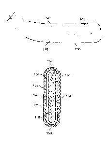
blade or stick.
Nevertheless, adding a significant amount of material may increase the weight
of the blade
and stick, and the use of softer core materials may lead to breakage of the
outer layer of the
sporting implement because of the amount of movement of the outer layer
allowed by the
core. In the case of a hockey stick blade, this may also create a "trampoline
effect" that
may make the puck bounce off of the blade that is more than desired. Also the
use of a
harder material for the core, may in certain instances, be either be too
fragile or too heavy.
Moreover, omitting the foam core in a hockey stick blade may create a
different "feel" of
the stick to the player because of the lack of damping.
SUMMARY
[04] The following presents a general summary of aspects of the disclosure in
order to provide a
basic understanding of the invention and various features of it. This summary
is not
1
CA 3034024 2019-02-14
intended to limit the scope of the invention in any way, but it simply
provides a general
overview and context for the more detailed description that follows.
Los]
Aspects of this disclosure relate to reducing the amount of cracks in a core
material by
absorbing energy between the outer layer, which can be a carbon skin, and the
core
material. If cracks form in the core, a layer of material can be configured to
fill the cracks
and to reduce the stiffness losses in the core. This may help to allow for
more consistency
during use of the sporting implement and allow the sporting implement to be
used for a
longer period of time.
[05a] According to one aspect, this disclosure relates to a blade for a hockey
stick. The blade
for a hockey stick comprises an outer layer; a core; and a dilatant material
positioned
between the core and the outer layer, the dilatant material forming a film;
and a recovery
gel positioned between the core and the dilatant material, wherein the
recovery gel is
compressible, shape recoverable, and pressurized to a predetermined pressure
and
configured to provide an integrated agent for filling cracks that appear
during use of the
blade, wherein the dilatant material is configured to exhibit a first
viscosity when the outer
layer of the blade is subjected to an impact force below a threshold level,
and a second
viscosity, higher than the first viscosity, when the outer layer of the blade
is subjected to
an impact force above the threshold level.
[05b] According to another aspect, this disclosure relates to a blade for a
hockey stick. The blade
for the hockey stick comprises a core comprising a dilatant material; an outer
layer
comprising carbon skin extending around the core; and a recovery gel formed as
a mixture
with the dilatant material, wherein the recovery gel is compressible, shape
recoverable,
and pressurized to a predetermined pressure and configured to provide an
integrated agent
for filling cracks that appear during use of the blade, wherein the dilatant
material is
configured to exhibit a first viscosity when the outer layer of the blade is
subjected to an
impact force below a threshold level, and a second viscosity, higher than the
first
viscosity, when the outer layer of the blade is subjected to an impact force
above the
threshold level
[05c] According to another aspect, this disclosure relates to a sporting
implement. The sporting
implement comprises a dilatant material configured to exhibit a first
viscosity when an
2
Date Recue/Date Received 2021-01-29
outer surface of the sporting implement is subjected to an impact force below
a threshold
level, and a second viscosity, higher than the first viscosity, when the outer
surface of the
sporting implement is subjected to an impact force above the threshold level;
and a
recovery gel, the recovery gel forming a film, the recovery gel being
compressible, shape
recoverable, and pressurized to a predetermined pressure and configured to
provide an
integrated agent for filling cracks that appear during use of the sporting
implement.
[05d] According to another aspect, this disclosure relates to a hockey stick.
The hockey stick
comprises a recovery gel. The recovery gel comprises polyurethane blended with
expandable microspheres. The recovery gel forms a film. The recovery gel is
compressible, shape recoverable, and pressurized to a predetermined absolute
pressure
that is above atmospheric pressure and configured to provide an integrated
agent for
filling cracks that appear during use of the hockey stick, wherein the
recovery gel is
applied to a foam core of the hockey stick as a discrete strip that extends
along a face of
a blade of the hockey stick, wherein the recovery gel is integrated into the
hockey stick
during fabrication and berate any clacks appeal in the hockey stick.
[05e] According to another aspect, this disclosure relates to a blade for a
hockey stick. The
blade comprises an outer layer, a core and a recovery gel comprising
polyurethane
blended with expandable microspheres, and positioned between the core and the
outer
layer, the recovery gel forming a film, wherein the recovery gel is
compressible, shape
recoverable, and pressurized to a predetermined absolute pressure that is
above
atmospheric pressure and configured to provide an integrated agent for filling
cracks that
appear during use of the blade, wherein the recovery gel is applied to the
core as a discrete
strip that extends along a face of the blade of the hockey stick, and wherein
the recovery
gel is integrated into the blade during fabrication and before any cracks
appear in the
blade.
[05f] According to another aspect, this disclosure relates to a method of
actively healing a blade
for a hockey stick. The method comprises forming an outer layer. The method
also
comprises forming a core. The method further comprises placing a recovery gel
comprising polyurethane blended with expandable microspheres between the core
and the
outer layer, the recovery gel forming a film. The method also comprises
configuring the
recovery gel to be compressible, and shape recoverable. The method further
comprises
2a
Date Recue/Date Received 2021-01-29
pressurizing the recovery gel to a predetermined absolute pressure that is
above
atmospheric pressure to provide an integrated agent for filling cracks that
appear during
use of the blade, wherein the recovery gel is applied to a foam core of the
hockey stick as
a discrete strip that extends along a face of a blade of the hockey stick,
wherein the
recovery gel is integrated into the hockey stick during fabrication and before
any cracks
appear in the hockey stick.
[05g] According to another aspect, this disclosure relates to a blade for a
hockey stick. The
blade comprises an outer layer, a core and a dilatant material positioned
between the core
and the outer layer and configured to exhibit a first viscosity when the outer
layer of the
blade is subjected to an impact force below a threshold level and a second
viscosity, higher
than the first viscosity, when the outer layer of the blade is subjected to an
impact force
above the threshold level. The core and the dilatant material are encapsulated
in a
deformable pocket.
[06] Other objects and features of the disclosure will become apparent by
reference to the
following description and drawings.
BRIEF DESCRIPTION OF THE DRAWINGS
107] A more complete understanding of the present disclosure and certain
advantages thereof
may be acquired by referring to the following detailed description in
consideration with
the accompanying drawings, in which:
108] Figure I generally illustrates a partial cross-section and perspective
view of an example
hockey stick in accordance with an aspect of the disclosure;
109] Figure 2A shows a side view of an example core in accordance with an
aspect of the
disclosure;
[10] Figure 2B shows a cross-sectional and front perspective view of the
example core of Figure
2A in accordance with an aspect of the disclosure;
[11] Figure 3A shows a cross-sectional view of an example blade in accordance
with an aspect
of the disclosure;
2b
Date Recue/Date Received 2022-03-09
112] Figure 3B shows another cross-sectional view of the example blade of
Figure 3A in a
molding operation in accordance with an aspect of the disclosure;
[13] Figure 3C shows an enlarged view of Figure 3A in accordance with an
aspect of the
disclosure;
2c
Date Recue/Date Received 2022-03-09
[14] Figure 4A shows yet another cross-sectional view of the example blade of
Figure 3A
during a molding operation in accordance with an aspect of the disclosure;
[15] Figure 4B shows an enlarged view of the example blade of Figure 3A after
a molding
operation in accordance with an aspect of the disclosure;
[16] Figure 5A shows a cross-sectional view of the example blade of Figure 3A
after a crack is
formed in accordance with an aspect of the disclosure;
[17] Figure 5B shows a cross-sectional view of the example blade of Figure 3A
showing a
recovery gel entering the crack is formed in Figure 5A in accordance with an
aspect of the
disclosure.
[18] Figure 5C shows a cross-sectional view of the example blade of Figure 3A
showing a
recovery gel sealing the crack fotnied in Figure 5A in accordance with an
aspect of the
disclosure.
[19] Figs. 6A-6C show example recovery gel application patterns.
[20] Figure 7 shows an exemplary process for forming an example blade in
accordance with an
aspect of the disclosure.
[21] Figure 8 schematically depicts a cross-sectional view of an example blade
that includes a
dilatant material, according to one or more aspects described herein.
[22] Figure 9 schematically depicts another cross-sectional view of an example
blade that
includes a dilatant material in combination with a recovery gel, according to
one or more
aspects described herein.
[23] Figure 10 schematically depicts a view of one implementation an internal
structure of a
hockey stick blade, according to one or more aspects described herein.
[24] Figure 11 schematically depicts a view of another implementation an
internal structure of a
hockey stick blade, according to one or more aspects described herein.
[25] Figure 12 schematically depicts a view of another implementation an
internal structure of a
hockey stick blade, according to one or more aspects described herein.
3
CA 3034024 2019-02-14
[26] Figure 13 schematically depicts a view of another implementation an
internal structure of a
hockey stick blade, according to one or more aspects described herein.
[27] The reader is advised that the attached drawings are not necessarily
drawn to scale.
DETAILED DESCRIPTION
[28] In the following description of various example structures in accordance
with the
invention, reference is made to the accompanying drawings, which form a part
hereof, and
in which are shown by way of illustration of various structures in accordance
with the
invention. Additionally, it is to be understood that other specific
arrangements of parts and
structures may be utilized, and structural and functional modifications may be
made
without departing from the scope of the present invention.
[29] Also, while the terms "top" and "bottom" and the like may be used in this
specification to
describe various example features and elements of the disclosure, these terms
are used
herein as a matter of convenience, e.g., based on the example orientations
shown in the
figures and/or the orientations in typical use. Nothing in this specification
should be
construed as requiring a specific three dimensional or spatial orientation of
structures in
order to fall within the scope of the claims.
[30] In general, as described above, aspects of this disclosure relate to
the repair of a core
structure. More specifically, aspects of the disclosure pertain to a recovery
gel that can be
used in conjunction with a sporting implement and methods for repairing a
sporting
implement, such as a hockey stick blade. More detailed descriptions of aspects
of the
disclosure follow.
[31] Fig. I illustrates a perspective view an example structure utilizing a
recovery gel with a
section of the blade 104 partially cut away. In this example, the sporting
implement can be
a hockey stick 100. However, it is contemplated that the repairing technique
could be used
in conjunction with other core structures outside of sporting implements and
other types of
sporting implements outside of hockey sticks, such as a lacrosse stick, bat,
racquet,
protective equipment, and the like. The example hockey stick 100 can include a
handle or
stick shaft 102 and a blade 104. In this example, the blade 104 can include an
outer layer
106, a recovery gel 108, and a core 110. As discussed below, the outer layer
106 can be a
4
CA 3034024 2019-02-14
skin formed of plies of carbon, which can be preimpregnated with a resin or
can be formed
as a dry material for use in a resin transfer molding (RTM) operation, The
recovery gel 108
can form a gel skin layer over the core 110.
[32] Figure 2A shows a side view of the example core 110, and Figure 2B shows
a cross-sectional
view of the core 110. As discussed below, in one example, the core 110 can be
formed of a
suitable foam. The core 110 can include a first core face 132, a second core
face 134, a top
core edge 136 and a bottom core edge 138.
133] In certain examples, the core 110 can be an epoxy core and can be made of
a B-staged epoxy
resin, which can include additives and expandable microspheres. During the
formation of
the core, the expandable microspheres cause the core to expand when exposed to
heat and
create compaction force to compress plies forming the outer layer together. As
will be
discussed below, in one example, the epoxy core can be preformed inside a
metal mold at
60 to 70 C for 1 min so it has a shape that is close to the final geometry
of the sporting
implement, which in this case is a blade. An example epoxy core with
expandable
microspheres is discussed in U.S. Pat. No. 9,364,988.
[34] In other examples, the core can be formed of a polymethacrylimide (PMI)
foam, and may be
a low density or a high density foam. In one example, a core structure is
described in U.S.
Pat. No. 9,295,890. It is further contemplated that additional or alternative
foam types may
be used in the hockey blade core.
[35] The recovery gel 108 can be placed on both sides, e.g. the first core
face 132 and the second
core face 134, of the preformed core 110 to provide a gel skin layer 108 that
extends between
the core 110 and the outer layer 106. In this example, the recovery gel 108
only partially
covers the blade in that the gel skin layer only extends along the first core
face 132 and the
second core face 134. In other examples, the recovery gel 108 can be only
applied to the
front face, only to the back face, or only on the edges of the blade.
Additionally, the recovery
gel can be applied to only part of front face, part of back face, part of
edges and various
combinations of the above. However, in other examples, the recovery gel can
form a film
Date Recue/Date Received 2020-06-19
recovery gel can form a film over the entire core of the blade including the
first core face
132, the second core face 134, the top core edge 136, and the bottom core edge
138.
[36] Figs. 6A-6C show different example applications of the recovery
gel 108 applied to the
core 110. Generally, the recovery gel 108 can be applied to sections of the
core 110 where
the blade encounters the most impacts. For example, in the striking region of
the blade
between the heel and the toe. As shown in Fig. 6A, the recovery gel 108 can be
applied to
the core 110 such that the recovery gel 108 tapers from the heel section to
the toe section of
the blade. Alternatively, as shown in Fig. 613, the recovery gel 108 can be
applied as a
rectangular shape to the core 110 and extends generally in the striking region
of the blade.
As shown in Fig. 6C, the recovery gel 108 can be applied as small strips of
material on the
core 110 also in the striking region of the blade. In each of these examples,
the patterns
can be applied to both the front face and back face regions of the blade. In
other examples,
a different pattern can be applied to the front face region than the back face
region of the
blade.
[37] The recovery gel 108 can be in the form of a memory shape gel such that
it is shape
recoverable. In this way, the recovery gel 108 offers some resistance to
spreading across
the surface of the core 110. If pressure is applied to the recovery gel 108,
it can move and
spread slightly. However, as soon as the pressure is removed, the recovery gel
108 will
reform into its original shape. This allows the recovery gel 108 to remain
uniform under
the carbon skin during the use of the blade as impacts occur. This also allows
the recovery
gel to be configured to absorb energy impacts between the outer layer and the
core of the
blade.
[38] The recovery gel can also be formed compressible, such that it can be
pressurized to a
predetermined pressure, which in one example can be up to 2 Bar. In this way,
the
recovery gel can be configured to provide an integrated agent for filling
cracks that appear
during use of the sporting implement. However, in other examples, the recovery
gel can
exhibit a very low pressure or no pressure at all. In one example, 5 +/- 1
grams of a
recovery gel can be applied on each side of the core 110. However, in other
examples, the
amount of recovery gel can range from 2 to 15 grams.
6
CA 3034024 2019-02-14
[39] Also, in one example, the recovery gel can be visco-elastic, which means
that with a high
speed rate of stress, the behavior of the recovery gel is close to a stiffer
material, similar to
a plastic, while if the speed rate of stress is low, the behavior is closer to
a fluid similar to
water. Without stickiness or tackiness, the recovery gel may slide between the
layers of
the blade (carbon skins and core) and may not transmit the shear stresses
resulting in a soft
blade.
[40] Various methods can be used to apply the recovery gel to the core. For
example, the
recovery gel can be brushed onto the core or brushed onto the prepreg or outer
carbon
layers. In other examples, the recovery gel can be brushed over a super-thin
layer of glass
fiber and then applied to the core or casted in a preform and applied to the
core. Also, a
thickness calibrated sheet of material or gel sheet can be formed, cut,
sprayed or dipped
with the recovery gel and then applied to the core. The sheet of material can
remain on the
structure or can be peeled away to act as a release layer. In certain
examples, the release
layer can be adhered to a piece of the prepreg that forms the outer layer,
which then is
wrapped around the core. In one example, the sheet of material can be die-cut
to the
desired shape such that the scrap rate is low and the efficiency is higher. In
yet another
example, the recovery gel may also be injected at the surface of the core with
a syringe.
[41] In certain examples, a suitable material for the recovery gel 108 can be
polyurethane
blended with expandable microspheres. This formulation helps to ensure the
cohesion of
the core material of a sandwich structure by integrating a material that will
fill cracks and
be sticky enough to transmit stresses. In some examples, the recovery material
can be a
blend of three different materials. For example, the recovery gel can be
polyurethane, with
a mix ratio of 1:5 by weight, microspheres from Expancel and a red dye gel
containing no
water solvent. Other example recovery gel materials may include silicone,
epoxy,
polyester, vinyl-ester, rubber, gelatin, hydrogels, organogels, xerogels, or
combinations
thereof. The recovery gel 108 can have the consistency of a paste and can have
a hardness
of 20 Shore 00 value once polymerized.
[42] In certain examples, red dye can be used to monitor and visualize the
material behavior of
the recovery gel inside the blade after cutting it. The red dye also helps to
determine the
misplacement and the degree of curing. Additionally, the dye can appear as a
"blood"
color to showcase a "living technology" to the end user. Without the dye, it
may be more
7
CA 3034024 2019-02-14
difficult to see where the recovery gel went relative to the core. For
example, the red dye
helps to confirm that the recovery gel did exactly what was expected during
the formation of
a crack. For example, a technician may see several thin red lines within the
epoxy core after
several impacts indicating that the recovery gel really did flow within the
crack to repair the
failure within the core.
[43] The core can then be wrapped with one or more carbon layers to form the
outer layer 106 of
the blade. For example, as illustrated in Fig. 3, the core 110 can be wrapped
with a layer of
carbon tape 140 that is optionally preimpregnated with resin, resulting in a
wrapped structure
160. The tape 140 can be, in one example, wrapped continuously around the
first core face
132, the second core face 134, the top core edge 136 and the bottom core edge
138 of the
core 110 and recovery gel 108. This continuous wrapping of the core 110 with
the tape 140
results in a first wrapped face 152, a second wrapped face 154, a top wrapped
edge 156 and
a bottom wrapped edge 158. It is to be understood that a layer of tape or
material need not
consist of a single unitary piece or sheet of material. For example, a layer
can consist of a
combination of multiple pieces or sheets that overlap.
[44] Once the foam core is wrapped with one or more layers of carbon tape 140,
a stitching or
tufting process may also be used to avoid any post-expansion of the blade
during the post-
curing steps. In one implementation, the stitching may extend through or
around recovery
gel 108. An example core and stitching process is described, for example, in
U.S. Pat. No.
9,295,890. In one example, the thread (not shown) may be a high strength
polyester thread
that can withstand heating and maintain its physical properties at and above
the temperature
of the mold, which in one example can range from 135 to 165 degrees C. In
other examples,
the thread may also be a carbon fiber thread or a carbon fiber thread
preimpregnated with
resin. In certain examples, the thread can be stitched onto the tape 140 in a
series of three
parallel lines of stitching. In alternative examples (not shown), eight
parallel lines of thread
are used. In other examples, there is no set or predetermined pattern to the
thread.
[45] The stitching or tufting process may be applied to the core after one or
more of the carbon
layers are applied to the blade. In one example, the foam core 110 can be
wrapped with a
single layer of carbon tape 140 before the stitching or tufting operation.
Wrapping the core
8
Date Recue/Date Received 2020-06-19
110 with too many layers of carbon tape prior to stitching may in certain
instances result in
wrinkling of the tape when it is stitched or tufted. The thread can extend
from the first
wrapped face 152 through the core 110 to the second wrapped face 154. The
thread creates
the effect of an I-beam between the first wrapped face 152 and the second
wrapped face
154 and adds structural and shear strength and rigidity between the faces. The
thread can
also pull the first wrapped face 152 and the second wrapped face 154 at the
point where the
thread enters the core 110. Hence, in certain examples, the wrapped, stitched
core is not
flat in that the result of the thread pulling the tape 140 toward the core 110
and various
locations creates a somewhat bumpy or pillow effect on the surface of the
first wrapped
face 152 and the second wrapped face 154. However, after the application of
the thread
through stitching or tufting, one or more layers of carbon tape 140 can be
added to the core
resulting in a smooth preform.
[46] It is also contemplated that a veil or scrim material (not shown) in the
form of a thin non-
tacky layer of woven fiberglass or polyester can be placed along the first
wrapped face 152
and the second wrapped face 154 to allow for stitching or tufting without
wrinkling the
tape or causing the machinery to otherwise stick or jam. The veil is placed on
the wrapped
faces 152, 154 in the manner of a sandwich, with a single layer of material on
each face.
[47] Once the carbon layers are applied onto the blade, the blade can be
molded separately or
together with the shaft of the stick. Figure 3B shows a schematic of a cross-
section of the
preform in a mold prior to the molding operation. As shown in Figure 3B, the
blade
construct can be placed into a mold 170, which can consist of a first mold
half 170A and a
second mold half 170B, where heat is applied to the preform. In one example,
the mold
170 can be formed of a suitable metal. Fig. 3C shows an enlarged view of the
preform
before the molding operation.
[48] As shown in Figure 4A, heat is applied to the mold and during the molding
operation, the
epoxy core 110 takes expansion and pushes the recovery gel 108 and the carbon
layers 106
against the mold walls, as indicated by the arrows in Figure 4A. In one
example, and as
discussed herein, the carbon layers 106 can be impregnated with an epoxy
resin. The
epoxy resin makes the carbon layers 106 somewhat impermeable to the recovery
gel 108.
Thus, in certain examples, where the recovery gel 108 is a shape recovery gel,
the recovery
gel 108 can be compressed and be pressurized to a predetermined pressure,
which in one
9
CA 3034024 2019-02-14
example can be up to 2 Bar. Also during the curing of the blade, the resin
impregnated in
the carbon layers or plies 106 crosslinks and becomes hard, and the epoxy in
the epoxy
core 110 also crosslinks and becomes hard. After curing, the recovery gel 108
becomes
entrapped and pressurized between the core 110 and the carbon layers 106,
which shown is
in the enlarged schematic of the construct in Figure 4B. However, the pressure
of the
recovery gel 108 is not high enough to deform the blade when the stick is
taken out of the
mold due to the stiffness of the carbon fibers. Nonetheless, the pressure of
the recovery gel
108 is sufficient to fill any cracks when they appear in the core or the outer
layer, e.g.
carbon layers 106.
[49] During use of the blade, the recovery gel 108 also creates a soft "feel"
or interface between
the epoxy core 110 and the carbon layer or skin 106 that receives impacts,
helping to
prevent the epoxy core 110 from cracking easily due to its relative
brittleness. Moreover,
in using a film, the carbon skins 106 can be limited in their movement and are
less likely to
fail by overpas sing their maximum strain. The recovery gel 108 allows the
outer layer 106
to deflect a limited amount to help prevent the outer layer 106 from tearing
or breaking,
which could occur with a fully soft core. In one example, the deflection or
movement of
the carbon layer 106 is limited to 0.5 ¨ 1 mm.
(501 Referring now to Figures 5A-5C if the core 110 or the outer layer 106 at
the recovery gel
interface cracks due to a large deformation or impact, the predetermined
pressure of the
recovery gel is relieved into the cracks or cavities formed by the cracks and
fills into the
cracks or cavity of the core. Specifically, as a crack 172 is formed in the
core 110, the
pressurized recovery gel 108 flows into the crack 172 as shown by the downward
pointing
arrow in Figure 5B. As shown in Figure 5C, this can provide cohesion between
separated
components, i.e., the outer carbon layer and the core and can recreate a new
material in the
place of the cracks or cavities. In essence, the recovery gel 108 recreates a
new foam
material where voids were created in the core 110. This allows the recovery
gel 108 to
help prevent cracks from propagating and to actively heal potential damages by
reducing
stiffness loss caused by cracks.
[51] In certain examples, the tackiness of the recovery gel 108 can be high,
meaning that there
are a lot of molecular functions available. For example, the recovery gel
surface in contact
with the core is very high allowing it to flow into small cracks or holes.
Moreover, the
CA 3034024 2019-02-14
recovery gel itself can include some weak links as a result of its formulation
and, thus,
would "prefer" to adhere with other structures, similar to polar molecules of
a degreasing
agent. This allows the recovery gel 108 to adhere to any cracks and, thus,
creates a new
bond between each side of the crack. Also, where expandable microspheres are
used in the
recovery gel, the expandable microspheres are useful in filling any major
cracks when they
occur.
[52] Additionally, if it becomes apparent that a crack has formed in the blade
meaning the core
is broken, for example, if the user hears a sound during use of the blade, the
stick can be
placed into an oven at 135 C for 3 to 5 minutes. This can be useful in
instances where it is
apparent that the recovery gel has not filled the space of the crack formed in
the blade or
where the entire pressure of the recovery gel has already been relieved by a
large amount
of cracks in the core. The heat applied to the blade can in certain examples
allow the
recovery gel to expand and fill in any major cracks in the core. The tackiness
of the gel
after curing the blade in the oven may be slightly lower but will still be
present should
additional cracks form in the core. In addition, when the recovery gel 108
cures in a crack,
the texture of the recovery gel changes to be more consistent with the texture
of a foam
material so that the feel of the sporting implement or hockey stick does not
change
significantly. The expandable microspheres inside the gel can expand as the
gel fills into
cracks in the core. The cracks create room for the gas in the expandable
microspheres to
expand. As the gel expands, the density can become lower (same weight but
bigger
volume). The overall material of the blade can feel and behave more like a
foam material
than the previous form of the recovery gel because the gas of the expanded
microspheres is
released resulting in a material closer to foam. Ilowever, the properties of
the recovery gel
remaining between the core and the outer layer will not change significantly
including its
texture.
[53] The hockey stick 100 may additionally include a dilatant material that
exhibits differing
material properties depending on the type of maneuver being performed with the
stick 100.
Advantageously, the dilatant material may offer a player a desirable
combination of a
softer feeling blade 104 when executing low-impact maneuvers with a puck, such
as stick
handling, and a harder feeling blade 104 when executing high-impact maneuvers,
such as a
slap shot.
11
CA 3034024 2019-02-14
[54] In particular, a dilatant material, otherwise referred to as a
shear-thickening material and/or
a non-Newtonian fluid, may exhibit increasing viscosity with increasing rate
of shear
strain. Accordingly, the blade 104 may include a dilatant material that may
exhibit a first,
comparatively low viscosity when the blade 104 is subjected to a comparatively
low
impact by a puck, such as when a player is stick handling, or executing a
wrist shot, among
others. Conversely, the dilatant material may exhibit a second, comparatively
higher
viscosity when the blade 104 is subjected to a comparatively high impact by a
puck, such
as when a player is executing a slap shot, among others. Accordingly, the
dilatant material
may be designed to exhibit a first viscosity when the outer layer 140 of the
blade 104 is
subjected to an impact force below a threshold force level, and a second
viscosity, higher
than the first viscosity, when the outer layer 140 of the blade 104 is
subjected to an impact
force above the threshold force level. It is contemplated that this threshold
force level may
be implemented with any value, without departing from the scope of these
disclosures.
[55] In one example, the blade 104 of the hockey stick 100 may include one or
more dilatant
materials made from polyethylene glycol that may be formed in combination with
silica
particles. Further, the dilatant material may be in the form of a deformable
gel that is
mixed with one or more polymers to &um a composite material. In one specific
example,
the polymer may be a polyurethane, or a combination of polyurethane and
expandable
microspheres. As such, the expandable microspheres may be similar to those
described in
U.S. Patent No. 9,802,369, filed 14 March 2008, the entire contents of which
are
incorporated herein by reference in their entirety for any and all non-
limiting purposes.
However, additional or alternative dilatant materials may be used with the
various
implementations described throughout this disclosure.
[56] In one example, the core 110 of blade 104 may be formed of a dilatant
material or
composite of a dilatant material and polymer, as described above. In another
example, a
dilatant material may be included in the recovery gel 108. Additionally, a
dilatant material
may form a layer 162 that partially or wholly surrounds the core 110. This
implementation
is schematically depicted in FIG. 8, which includes several elements described
in relation
to FIG. 3A, in addition to the dilatant material layer 162. In another
example, a dilatant
material may form a layer 162 that partially or wholly surrounds the recovery
gel 108.
12
CA 3034024 2019-02-14
This implementation is schematically depicted in FIG. 9, which includes
several elements
described in relation to FIG. 3A, in addition to the dilatant material layer
162.
[57] In one example, the dilatant material layer 162 depicted in FIGS. 8 and 9
may be
encapsulated within a deformable pocket. This pocket may be formed from any
suitable
polymer, and may have any size and geometry, without departing from the scope
of these
disclosures. Alternatively, the dilatant material layer 162 depicted in FIGS.
8 and 9 may be
implemented as a gel, or solid material that is applied directly to the blade
104 without
additional encapsulation.
[58] In another implementation, a dilatant material, similar to the
dilatant material layer 162,
may be used within one or more portions of a hockey stick shaft 102. As such,
the dilatant
material may exhibit a variable hardness when a player is gripping the hockey
stick shaft
102 under differing circumstances. Advantageously, the use of a dilatant
material 162
within one or more portions of a hockey stick shaft 102 may improve inter-
laminar shear
performance of the shaft material.
[59] It is further contemplated that a dilatant material may be used at any of
the locations
previously discussed in relation to the recovery gel 108, and may be used in
addition to, or
as an alternative to the recovery gel 108 may, without departing from the
scope of these
disclosures. For example, a dilatant material may be integrated into a hockey
stick core
110 with geometries similar to those described in relation to the recovery gel
108 in FIGS.
6A-6C.
[60] FIG. 10 schematically depicts a hockey stick blade 1000 that may include
a dilatant
material and a recovery gel, according to one or more aspects described
herein. In
particular, FIG. 10 schematically depicts an internal view of the hockey stick
blade 1000
with an outer surface of the blade removed. As such, in one example, area 1002
may
include a dilatant material, as previously described. Further, area 1004 may
include a
recovery gel, as previously described in relation to recovery gel 108. In
another example,
area 1002 may include a combination of a dilatant material and a recovery gel,
and area
1004 may include a foam core.
13
CA 3034024 2019-02-14
[61] FIG. 11 schematically depicts another example implementation of a hockey
stick blade
1100. The hockey blade 1100 is shown having a toe region 1106, a middle region
1108
and a heel 1110. A core 1102 of the hockey blade 1100 can be formed of a first
lower
density foam core portion 1102A and a second higher density foam core portion
1102B.
The first core portion 1102A can be stitched using a thread 1112. The second
core portion
1102B can be formed of an epoxy having a plurality of polymeric shell
microspheres.
Additionally or alternatively, the second core portion 1102B may include a
dilatant
material, as previously described to read these disclosures. The first core
portion 1102A
and the second core portion 110211 are bonded to form the continuous core
1102. In
particular, the first core portion 1102A has a bottom surface 1104A which is
bonded to a
top surface 1104B of the second core portion 1102B during a molding and cross-
linking
process.
[62] The first core portion 1102A extends from the heel 1110 of the blade to
the toe region 1106
of the blade. The first core portion 1102A can be formed thickest at the heel
1110 of the
blade and can taper from the heel 1110 of the blade to the toe region 1106 of
the blade.
Forming the first core portion 11102A thickest or widest in the heel 1110
compensates for
the loss of stiffness due to the lower density and lower modulus of the foam.
The second
core portion 110211 extends from the toe region 1106 of the blade to the heel
1110 of the
blade 1100. The second core portion can be thickest at the toe region 1106 of
the blade
1100 and can taper from the toe region 1106 of the blade 1100 to the heel 1110
of the blade
1100. Both the first core portion 1102A and the second core portion 1102B can
extend all
the way to the toe edge 1114 of the blade 1100. It is understood, however,
that other
arrangements and ratios of the core portions 1102A, 1102B can be formed to
accomplish
different stick characteristics, weights, and strengths. For example, the core
portions can
be formed in different arrangements as shown in FIGS 12 and 13, the
description of which
follows.
[63] FIG. 12 shows an alternative arrangement. The blade 1200 comprises a
first core portion
1202A and second core portion 1202B, which makes up the core 1202. In one
example,
the second core portion 1202B may include a dilatant material. The arrangement
is similar
to the arrangement in FIG. 11 with the exception that the first core portion
1202A does not
extend as far down the blade 1200. In addition, the joint 1216 between the
first core
14
CA 3034024 2019-02-14
portion 1202A and the second core portion 1202B forms a straighter line. The
straight line
joint 1216 is advantageous as it may reduce the overall stress on the blade
during use.
[64] Another alternative arrangement is shown in FIG. 13. The embodiment shown
in FIG. 13
is similar to the embodiments shown in FIGS. 11 and 12. However, the core 1302
of the
blade 1300 has first and second core portions 1302A and 1302B that are formed
with an
oval-like shape at one end and a hook shape at the other end to receive the
respective oval-
like shaped ends. In one example, the second core portion 1302B may include a
dilatant
material. If one of the core portions 1302A or 1302B is formed with an epoxy,
this
arrangement and shaping of the first and second core portions 1302A and 1302B
allows for
the epoxy to flow and fill more evenly in the formation process.
[65] In other examples, the core of the blade can be manufactured by forming a
construct of
multiple cores or foams. Different combinations of core materials are used to
create
distinct recipes of core mixtures. The different mixtures can be used to
create a blade with
zones of varying density and stiffness. Core mixtures with higher density
materials can be
placed in the areas of the blade subject to greater forces and impacts, such
as the bottom or
heel, to create stronger blade regions. For instance, the bottom of the blade
and the heel of
the blade are typically subject to the most force and impact from striking the
ice or a
hockey puck. For example, the different cores can be placed on various
locations of the
blade to create a blade with zones of varying density, such as the top or the
toe of the blade
to reduce weight. Higher density foam can be placed along the bottom of the
blade where
the blade is subjected to high impacts and lower density foam can be placed at
an upper
portion of the blade where the blade is subject to fewer impacts. One such
example core is
discussed in U.S. Pat. No. 9,289,662, the entire contents of which are
incorporated herein
by reference for any and all non-limiting purposes. Where different cores or
foams are
used the core could be provided with more than one type of recovery gel such
that each
core or foam is provided with a specific recovery gel that is most suitable
for filing cracks
that form in the particular core or foam. For example, recovery gels could be
placed inside
carbon compartments to divide the recovery gels across the blade. Also, the
recovery gels
could potentially have a different absorption or feel across the length of the
blade to
provide different properties when cracks form.
CA 3034024 2019-02-14
[66] An example process of manufacturing a blade in accordance with the
disclosure is
illustrated in Fig. 6. First a foam core is formed as shown at step 202. Next
a recovery gel
can be added to the foam core at 204 such that it is applied to each face of
the core or such
that the recovery gel extends around the foam core entirely. For example,
multiple sheets
of material containing the recovery gel can be formed, weighed, and cut. The
sheets of
material, which can be small inserts or parts, are then adhered on the desired
portions of the
core. In other examples, as discussed above, the recovery gel can be brushed
onto the core,
brushed onto the outer layer, or injected. In other examples, the recovery gel
can be
brushed over a super-thin layer of glass fiber and then applied to the core or
castcd in a
preform and applied to the core.
[67] The foam core is then wrapped with a first layer or layers of carbon or
fiber tape as shown
at 206. The first layer of carbon or fiber tape extends continuously along the
first core
face, top core edge, second core face and bottom core edge of the foam core,
such that the
wrapped core has a first wrapped face, a second wrapped face, a top wrapped
edge and a
bottom wrapped edge. Optionally, a non-sticky veil can be applied to the first
wrapped
face and second wrapped face to assist with a stitching or tufting process.
The wrapped
foam core can then be stitched or tufted with a thread as shown at 208. The
thread extends
between and along the first wrapped face and the second wrapped face. The
stitched
wrapped core may be wrapped with a second layer or layers of fiber tape to
form a
wrapped preform, as shown at 210. The second layer of fiber tape extends
continuously
atop the first layer of fiber tape and along the first wrapped face, the top
wrapped edge, the
second wrapped face, and the bottom wrapped edge.
[68] The wrapped preform is then placed in a mold, as shown at 212, and the
mold is heated to
an appropriate temperature. In one example, the mold is heated to between 135
to 165
degrees C, and in one particular example, the mold can be heated to 160
degrees C. The
heating causes the recovery gel to become pressurized between the core and the
layers of
fiber tape. The resin in the preimpregnated tape melts, flows through the
woven veil, if
used, crosslinks and bonds the layers of fiber tape together. When the
recovery gel is
applied it can be placed to avoid direct contact between the layers of carbon
and the core.
When recovery gel inserts are used, contact between the layers of carbon and
the core is
avoided in the location of the insert but the remainder of the layers of
carbon and the core
16
CA 3034024 2019-02-14
of the blade are in direct contact. However, if the core is entirely covered
with the
recovery gel around the core, no bonding will occur between the epoxy core and
the carbon
prepreg layers. In one example, the recovery gel that is applied to the core
before molding
can be already polymerized at 100% and, thus, during formation does not
crosslink to the
layers of carbon and core.
[69] Additionally, when the mold is heated, the resin in the preimpregnated
tape can flow along
the threads and into the core. When this resin cools, it creates additional
strength in the z-
axis of the structure. Carbon fiber thread, which may be used in one example,
shrinks
when it is heated. Carbon fiber thread results in a more homogenous structure
because the
carbon fiber thread shares properties with the carbon fiber tape. The thread
can also create
a stiffening agent that gives additional resistance against shearing. The mold
is then
cooled, and the formed structure is removed from the mold.
[70] It is also contemplated that the blade could be formed using a resin
transfer molding
(RTM) process. In such a case, the recovery gel can be encapsulated between
the core and
the outer layer. However, the recovery gel would not be configured to flow
into a crack or
tear in the core during use of the blade. Nevertheless, if a crack is formed
in the core of an
RTM formed blade, heating the blade will force the microspheres to expand and,
thus, fill
the crack. Therefore, a blade formed by RTM can be configured to be healable
by heating
the core or by "thermal-healing" the core.
[71] In one example, a sporting implement can include a recovery gel, which
can be a memory
shape gel. The recovery gel can form a film within the sporting implement. The
recovery
gel can be compressible, shape recoverable, and pressurized to a predetermined
pressure so
as to provide an integrated agent for filling cracks that appear during use of
the sporting
implement. The sporting implement may include an outer layer and a core, and
the
recovery gel can be configured to absorb energy impacts between the outer
layer and the
core. The core can be formed of an epoxy, and the outer layer may include a
carbon skin
to form a blade for a hockey stick. The recovery gel may allow the outer layer
to deflect
no more than 0.5 to 1 mm and to help prevent the outer layer from tearing or
breaking.
When a crack appears, the predetermined pressure can be relieved inside the
crack and fill
a cavity formed by the crack to provide cohesion between separated components
to
recreate a new material in the place of the crack. In one example, the
predetermined
17
CA 3034024 2019-02-14
pressure can be 0 to 2 Bar. The recovery gel can be configured to help prevent
cracks from
propagating and actively heals potential damages by reducing stiffness loss
caused by
cracks. The recovery gel can include a polyurethane blended with expandable
microspheres.
[72] In another example, a blade for a hockey stick may include an outer
layer, a core, and a
recovery gel positioned between the core and the outer layer. The recovery gel
can fonn a
film, and the recovery gel can be compressible, shape recoverable, and
pressurized to a
predetermined pressure and configured to provide an integrated agent for
filling cracks that
appear during use of the blade. The recovery gel can be configured to absorb
energy
impacts between the outer layer and the core. The recovery gel can partially
cover a
surface of the core, or alternatively, the recovery gel can cover an entire
surface of the
core.
[73] Also the core can be formed of an epoxy, and the outer layer may include
a carbon skin.
The recovery gel can allow the outer layer to deflect no more than 0.5 to 1 mm
and to help
prevent the outer layer from tearing or breaking. When a clack appears, the
predetermined
pressure can be relieved inside the crack and fills a cavity folined by the
crack to provide a
cohesion between the outer layer and the core to recreate a new material in
the place of the
crack In one example, the predetermined pressure is 0 to 2 Bar. The recovery
gel can be
configured to help prevent cracks from propagating and actively heals
potential damages
by reducing stiffness loss caused by cracks. The recovery gel can include a
polyurethane
blended with expandable micro spheres.
[74] In yet another example, a method of actively healing a blade for a hockey
stick may
include forming an outer layer, forming a core, and placing a recovery gel
between the core
and the outer layer. In one example, the recovery gel can form a film. 'The
method may
also include configuring the recovery gel to be compressible, and shape
recoverable and
pressurizing the recovery gel to a predetermined pressure to provide an
integrated agent for
filling cracks that appear during use of the blade. The method may also
include
configuring the recovery gel to absorb energy impacts between the outer layer
and the core,
forming the core of an epoxy and forming the outer layer of a carbon skin and
configuring
the recovery gel to allow the outer layer to deflect no more than 0.5 to 1 mm
and to help
prevent the outer layer from tearing or breaking. Additionally the method may
include
18
CA 3034024 2019-02-14
configuring the predetermined pressure of recovery gel to be relieved inside a
crack to fill a
cavity formed by the crack to provide a cohesion between the outer layer and
the core to
recreate a new material in the place of the crack, setting the predetermined
pressure to 0 to
2 Bar, configuring the recovery gel to help prevent cracks from propagating
and to actively
heal potential damages by reducing stiffness loss caused by cracks, forming
the recovery
gel of a polyurethane blended with expandable microspheres, and heating the
blade at
135 C for 3 to 5 minutes to help fill cracks.
[75] In one implementation, a blade for a hockey stick may include an outer
layer, core, and a
dilatant material positioned between the core and the outer layer, with the
dilatant material
foiming a film. The dilatant material may be configured to exhibit a first
viscosity when
the outer layer of the blade is subjected to an impact force below a threshold
level. The
dilatant material may be configured to exhibit a second viscosity, higher than
the first
viscosity, when the outer layer of the blade is subjected to an impact force
above the
threshold level.
[76] In one example, a dilatant material may be encapsulated within a
deformable pocket
between an outer layer and a core of a hockey stick blade.
[77] In another example, a dilatant material may be combined with a polymer to
fomi a
composite material. The polymer may be a polyurethane, or a mixture of
polyurethane and
expandable micro spheres.
[78] A dilatant material used in a blade of a hockey stick may include a
polyethylene glycol in
combination with silica particles.
1791 A core of a hockey stick blade may be formed of an epoxy and an outer
layer of a hockey
stick blade may be formed of a carbon skin.
[80] A blade of a hockey stick may additionally include a recovery gel
positioned between a
core and a dilatant material, such that the recovery gel may be compressible,
shape
recoverable, and pressurized to a predetermined pressure. The recovery gel may
be
configured to provide an integrated agent for filling cracks that may appear
during use of
the blade.
19
CA 3034024 2019-02-14
[81] A blade of a hockey stick may additionally include a recovery gel formed
as a mixture with
a dilatant material, such that the mixture has dilatant material properties
and material
properties of a recovery gel.
[82] In another implementation, a blade for a hockey stick may include a core
that includes a
dilatant material, and an outer layer that includes a carbon skin extending
around the core.
The dilatant material may be configured to exhibit a first viscosity when the
outer layer of
the blade is subjected to an impact force below a threshold level. The
dilatant material
may be configured to exhibit a second viscosity, higher than the first
viscosity, when the
outer layer of the blade is subjected to an impact force above the threshold
level.
[83] In one example, the dilatant material may allow the outer layer of the
hockey stick blade to
deflect by no more than 0.5 to 1 mm to prevent the outer layer from tearing or
breaking.
[84] In another example, a dilatant material may be combined with a polymer to
form a
composite material. The polymer may be a polyurethane, or a mixture of
polyurethane and
expandable micro spheres.
[85] In one example, a dilatant material used in a blade of a hockey stick may
include a
polyethylene glycol in combination with silica particles.
[86] A blade of a hockey stick may additionally include a recovery gel
positioned between a
core and an outer layer of the blade, such that the recovery gel may be
compressible, shape
recoverable, and pressurized to a predeteiiiiined pressure. The recovery gel
may be
configured to provide an integrated agent for filling cracks that may appear
during use of
the blade.
[87] A blade of a hockey stick may additionally include a recovery gel formed
as a mixture with
a dilatant material, such that the mixture has dilatant material properties
and material
properties of a recovery gel.
[88] In another implementation, a sporting implement may include a dilatant
material that is
configured to exhibit a first viscosity when the outer layer of the sporting
implement is
subjected to an impact force below a threshold level. The dilatant material
may be
CA 3034024 2019-02-14
configured to exhibit a second viscosity, higher than the first viscosity,
when the outer
layer of the sporting implement is subjected to an impact force above the
threshold level.
[89] In another example, a dilatant material may be combined with a polymer to
form a
composite material. The polymer may be a polyurethane, or a mixture of
polyurethane and
expandable microspheres.
[90] A dilatant material used in a sporting implement may include a
polyethylene glycol in
combination with silica particles.
[91] A sporting implement may additionally include a recovery gel that forms a
film and is
compressible, shape recoverable, and pressurized to a predetermined pressure.
The
recovery gel may be configured to provide an integrated agent for filling
cracks that may
appear during use of the sporting implement.
[92] A recovery gel used in a sporting implement may be mixed with a dilatant
material.
[93] In one example, an outer layer of a sporting implement formed of a carbon
skin may
encapsulate a dilatant material.s
[94] The reader should understand that these specific examples are set
forth merely to illustrate
examples of the disclosure, and they should not be construed as limiting this
disclosure.
Many variations in the connection system may be made from the specific
structures
described above without departing from this disclosure.
[95] While the invention has been described in detail in terms of specific
examples including
presently preferred modes of carrying out the invention, those skilled in the
art will
appreciate that there are numerous variations and permutations of the above
described
systems and methods. Thus, the spirit and scope of the invention should be
construed
broadly as set forth in the appended claims.
21
CA 3034024 2019-02-14