Note: Descriptions are shown in the official language in which they were submitted.
1
MARINE ENERGY STORAGE UNIT, AND A METHOD TO PREVENT THERMAL
RUNAWAY IN A MARINE ENERGY STORAGE UNIT
Field of the invention
The present invention relates to a marine energy storage unit with thermal
runaway
safety barriers to prevent cell temperature increase, and a method to prevent
thermal
runaway in a marine energy storage unit.
Background of the invention
Energy storage systems with for instance lithium-ion battery cells are used in
many
applications, such as electric ferries, hybrid offshore vessels, hybrid
drilling rigs,
cranes and other applications with high current requirements.
In recent years many ship designers have started to replace conventional
diesel- or
gas engines with battery packs, or the diesel- or gas engines work together
with
battery packs.
Thermal runaway can be a problem in such energy storage systems. Thermal
runaway occurs in situations where an increase in temperature changes the
conditions in a way that causes a further increase in temperature, often
leading to a
destructive result.
In electrical engineering, thermal runaway is typically associated with
increased
current flow and power dissipation, although exothermic chemical reactions can
be
of concern here too.
Some electronic components develop lower resistances or lower triggering
voltages
(for nonlinear resistances) as their internal temperature increases. If
circuit
conditions cause markedly increased current flow in these situations,
increased
power dissipation may raise the temperature further by Joule heating. A
vicious circle
or positive feedback effect of thermal runaway can cause failure, sometimes in
a
spectacular fashion (e.g. electrical explosion or fire). To prevent these
hazards, well-
designed electronic systems typically incorporate current limiting protection,
such as
thermal fuses, circuit breakers, or PTC current limiters.
To handle larger currents, circuit designers may connect multiple lower-
capacity
devices (e.g. transistors, diodes, or MOVs) in parallel. This technique can
work well,
but is susceptible to a phenomenon called current hogging, in which the
current is
not shared equally across all devices. Typically, one device may have a
slightly
CA 3034193 2019-02-19
2
lower resistance, and thus draws more current, heating it more than its
sibling
devices, causing its resistance to drop further. The electrical load ends up
funneling
into a single device, which then rapidly fails. Thus, an array of devices may
end up
no more robust than its weakest component.
The current-hogging effect can be reduced by carefully matching the
characteristics
of each paralleled device, or by using other design techniques to balance the
electrical load. However, maintaining load balance under extreme conditions
may not
be straightforward. Devices with an intrinsic positive temperature coefficient
(PTC) of
electrical resistance are less prone to current hogging, but thermal runaway
can still
occur because of poor heat sinking or other problems.
Many electronic circuits contain special provisions to prevent thermal
runaway. This
is most often seen in transistor biasing arrangements for high-power output
stages.
However, when equipment is used above its designed ambient temperature,
thermal
runaway can still occur in some cases. This occasionally causes equipment
failures
in hot environments, or when air cooling vents are blocked.
Thermal runaway in marine energy storage systems occurs mainly due to heavy
load
cycles, which increases internal temperature in the stacks of lithium-ion
battery cells.
Thermal runaway can also occur due to cell production failure, internal or
external
electrical failures or external heat sources.
Such energy storage systems can be housed in an IP cabinet or enclosure. The
International (or Ingress) Protection IP rating system defines an enclosure's
protective capacity, and then assigns an IP Code. The code labels an
enclosure's IP
followed by two numbers; the first digit shows the extent to which equipment
is
protected against particles, and the second digit indicates the extent of
protection
against water. For instance IP54 enclosures have a high level of protection
against
particles, and a fair amount of protection against water.
Disclosure of the state of art
Low-cost battery modules available today are designed for use in bulk energy
land
applications. These systems require the use of fire suppression systems, they
have
no failure containment (i.e. vent gases to room), and the packaging typically
does not
comply with marine requirements.
CA 3034193 2019-02-19
3
A disadvantages with the known systems can be that the rack releases energy to
the
battery room from the full module, and they therefore require fire suppression
systems.
It is also known marine energy storage systems that are designed as a modular,
stackable and configurable energy storage building block. Each module is
comprised
of several lithium-ion battery cells. The cells can be encased in a metal
housing for
protection, cooling and safety. These modules are connected in series to
achieve
bus voltage and parallel strings are added together to meet the total required
system
capacity. Water cooling is used directly on the battery cells.
Such modules can be housed in racking systems and in containers. The rack
construction provides mechanical protection, integrated cooling and an
external
venting system.
US 2015/0101355 Al discloses an air conditioning system and method for a high-
voltage battery of a vehicle. The system includes a first heat exchanger that
is
disposed within a battery housing and a first blower that supplies air to the
first heat
exchanger. A peltier element is combined with the first heat exchanger and a
first
surface of the peltier element comes into contact with the first heat
exchanger. A
second heat exchanger is disposed in an air extraction unit of a trunk room
and a
second blower supplies air to the second heat exchanger, to discharge air
inside the
trunk room to an exterior after performing heat exchange. A cooling line
operates as
a coolant circulating line, and a first end of the cooling line comes into
contact with a
second surface of the peltier element and a second end performs heat exchange
between the second end and the second heat exchanger.
KR 101614688 B discloses a battery pack for airtight electric ships. The
battery pack
comprises: a battery pack case including an upper case and a lower case; an
air
layer/cooling water layer forming part including an upper air layer/cooling
water layer
forming part and a lower air layer/cooling water layer forming part; and a
flexible
closed end including a first flexible closed end and a second flexible closed
end. By
having an airtight structure, the battery pack can achieve conditions required
as the
battery pack for electric ships, including vibration, impact, waterproofness,
dustproofness, and thermal radiation.
CA 3034193 2019-02-19
4
Objects of the present invention
On marine vessels, in particular electric and hybrid vessels, there is thus a
need for
energy storage unit or enclosure on a marine platform, in where the mentioned
disadvantages can be avoided.
The invention will enable mass production of battery modules in the marine
segment
to reduce financial risk, price, increase quality and enable more marine
battery
installations, hence reducing global emissions.
The invention also provides increased safety due to multiple safety barriers,
gives
simpler vessel integration, and "battery room" in a box. It can also cover the
ageing
aspect in propagation control.
With the invention it is possible to use low-cost land modules in a sealed
cabinet that
will allow any fire suppression system to be used, and confine a module
thermal
event to a small defined space. It is expected that the invention can provide
a low-
cost energy storage solution that offers substantial reduction in the
installed price
compared to today's market prices.
A further object is application of fresh water or sea water for use in the
cooling
systems.
It is also an object to provide a system and a method with several thermal
runaway
safety barriers to prevent cell temperature increase.
Summary of the invention
The above objects are achieved with a marine energy storage unit with thermal
runaway safety barriers to prevent cell temperature increase, said marine
energy
storage unit comprises at least one closed module cabinet with a plurality of
stacked
battery cells and an internal cooling system, wherein the internal cooling
system
comprises an enclosed cabinet cooling circuit with a water-to-air exchanger
for air
cooling of the battery cells, and the water-to-air exchanger is connected to a
water-
to-water heat exchanger for receipt of water from an external source.
The enclosed cabinet cooling circuit is preferably a first safety barrier
arranged to
prevent cell temperature increase.
CA 3034193 2019-02-19
5
The module cabinet can comprise an additional safety barrier with a cooling
medium
unit, said cooling medium unit being arranged to release cooling medium in the
cabinet cooling circuit in case of temperature increase.
The module cabinet can comprise an additional safety barrier with an gas unit,
said
gas unit being arranged to release gas in the cabinet cooling circuit in case
of
temperature increase.
The module cabinet can comprise additional safety barriers based on oxygen
removal or cooling mediums, said additional safety barriers being arranged to
release gas or cooling medium in the cabinet cooling circuit in case of
detection of
gas, such as hydrogen.
The cooling medium units and the gas units can be connected to one or more
temperature sensors in the module cabinet.
The cooling medium units and the additional safety barrier units can be housed
in
separate sections in the closed module cabinet or externally as separated
units
The module cabinet can also comprise an additional safety barrier, said
additional
barrier being an extraction fan arranged to start if a lower explosion limit
is reached.
The module cabinet can further comprise an additional safety barrier, said
additional
barrier being a water mist system arranged to be released in case of thermal
runaway.
The water-to-water heat exchanger is preferable connected to a circulation
pump
pumping in sea water, wherein the sea water is temperature regulated in the
water-
to-water heat exchanger.
The water-to-air exchanger can comprise a fan directing cooling air to the
battery
cells.
The stacked battery cells can be lithium-ion batteries.
Several module cabinets can be connected in series forming a string.
CA 3034193 2019-02-19
6
The above objects are also achieved with a method to prevent thermal runaway
in a
marine energy storage unit, said marine energy storage unit comprises at least
one
closed module cabinet with a plurality of stacked battery cells and an
internal cooling
system, wherein the method comprises the steps:
regulation of water temperature in water supplied to a water-to-air exchanger
in an
enclosed cooling circuit in the cabinet, and
directing air directly to the battery cells, wherein the air is cooled in the
water-to-air
exchanger.
For regulation of water temperature in water supplied to the water-to-air
exchanger,
the water-to-air exchanger can be connected to a water-to-water heat exchanger
receiving water from an external source.
The method may further comprises the steps: in case the previous safety
barrier fails
and cell or cabinet temperature increases to thermal runaway, releasing a
cooling
medium in the cabinet cooling circuit.
The method may further comprises the steps: in case the previous safety
barriers fail
and cell or cabinet temperature continues into thermal runaway, releasing a
gas
medium in the cabinet cooling circuit.
The method may further comprises the steps: in case the previous safety
barriers fail
and detection of gas and thermal runaway temperature, releasing a gas in the
cabinet cooling circuit.
The method may further comprises the steps: in case the previous safety
barriers fail
and lower explosion limit is reached, disconnecting non ex-rated equipment and
staring an extraction fan.
The method may further comprises the steps: in case the previous safety
barriers fail
and detection of thermal runaway, releasing a water mist into the cabinet
preventing
propagation of fire.
Description of the figures
Embodiments of the present invention will now be described, by way of example
only, with reference to the following figures, wherein:
CA 3034193 2019-02-19
7
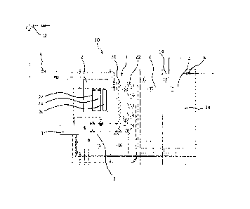
Figure 1 shows a first embodiment of a modular cabinet according to the
invention.
Figure 2 shows the modular cabinet connected to an external cooling system.
Figure 3 shows an internal cooling system of the modular cabinet.
Figure 4 shows a second embodiment of a modular cabinet according to the
invention.
Description of preferred embodiments of the invention
A marine energy storage unit according to the invention may comprise several
modular cabinets 10 as shown in figure 1, 2 and 4. The modular cabinets 10 can
be
connected in series forming a string. Each string may have an independent
electrical
connection to the DC-link.
The invention will however in the following be described in relation to a
marine
energy storing unit with one modular cabinet 10. Reference number 10 is given
to
the embodiment shown in both figure 1 and 4.
The modular cabinet 10 has as main features: a control section 1, a fire
suppression
section 2, an internal cooling circuit 3, a string section with stacked
battery cells 4, a
thermal runaway piping interface 5, an inlet air valve 6 and a water cooling
interface
7. The battery cells 4 are preferable lithium-ion batteries.
The lithium-ion battery cells 4 can be stacked in the module cabinet 10 with
for
instance two cells in parallel and the rest in series.
The marine energy storage unit is thus a module based cabinet design. Each
modular cabinet 10 comprises control, fire suppression, cooling and several
string
sections. The modular cabinet 10 is designed to be IP isolated from the room
environment. The cabinet may have an IP 54 enclosure, or other IP enclosures
dependent on requirements, and will not need to use air from the room to cool
the
battery cells 4. The external cooling interface is preferable fresh-water or
sea water.
The cabinet 10 is connected to an external water-to-water exchanger 30, and
the
cabinet 10 has an internal heat exchanger 20 with water-to-air conversion and
an
internal ducting system 24. The external water-to-water exchanger 30 and the
internal heat exchanger 20 are interconnected in the water cooling interface
7.
CA 3034193 2019-02-19
B
In addition, the cabinet 10 has an internal fire suppression system to prevent
explosion, fire and battery module propagation in case of a thermal runaway
event in
a battery module 4. The interfaces required for the cabinet design is external
cooling
water, received from the water-to-water exchanger 30 at for instance 6-17 C,
gas
extraction ventilation, electrical DC main power, auxiliary power supply and
control
interface 1.
Each modular cabinet 10 in the marine energy storage unit can have several
thermal
runaway safety barriers to prevent battery cell temperature increase. A
possible first
safety barrier is the cabinet cooling design, which is based on the internal
and
enclosed cooling circuit 3. Hence, cooling of the room environment may not be
required. The internal cooling circuit 3 will keep the battery cells 4 in the
cabinet
string module at for instance 23 C +1- 5 C if the ambient air temperature is
maximum
45 C and the cooling water is for instance 6-17 C.
The internal cooling circuit 3 is shown in more detail in figures 1, 3 and 4,
and
comprises the water-to-air exchanger 20 receiving water via the water
interface 7 in
a line L21. Used water from the water-to-air exchanger 20 exits via a line L31
to the
water interface 7. Air Ac passing the water-to-air exchanger 20 is cooled and
is
directed to pass the battery cells 4 by one or more fans 22, as shown by the
arrows
in figure 3.
In order to supply water of optimal temperature to the water-to-air exchanger
20 in
the cabinet 10, the external water-to-water heat exchanger 30 is connected to
the
water interface 7. The external water-to-water heat exchanger 30 receives
water
from an external source, such as sea or fresh water, via a line L1, to the
water-to-
water heat exchanger 30, and further to the water interface 7 of the cabinet
10. The
external water may have a temperature of for instance 0-32 C, but the water to
the
water-to-air exchanger 20 in the cooling circuit 3 can be maintained at for
instance a
temperature range of 6-17 C, after being cooled, or heated, in the water-to-
water
heat exchanger 30.
Figure 2 shows the external water supply system connected to the cabinet 10.
The
water can be pumped using one or two circulation pumps 32. A pressure tank 34
and
valve 36 may also be incorporated in the system. Water from the water-to-air
exchanger 20 exits the water interface 7 via a line L3 to the valve and can
flow to the
CA 3034193 2019-02-19
9
line L2 via the valve 36 or to the water-to-water heat exchanger 30, in where
it can
be cooled again or released externally.
As mentioned, each modular cabinet 10 in the marine energy storage unit has
several thermal runaway safety barriers. Some of the barriers are optional
depending
on the technology put into the energy storage unit. How many barriers that
needs to
be used and the activation sequence of the safety barriers is dependent on the
battery cell and battery modules used/placed inside the energy storage unit.
For thermal detection can one or more temperature sensors T, T1 be mounted
inside
the battery module, and also in the air-inlet and outlet on the battery module
or
cabinet 10.
In case a first safety barrier fails and cell or cabinet temperature increases
to thermal
runaway, a cooling medium can be released in the cabinet cooling circuit 3.
This is
an additional and possible second safety barrier. Releasing cooling medium
(for
instance gas or water-mist) will reverse the thermal runaway so that no gas
release
or fire occur. In fig. 1, cooling medium in the form of gas can be released
from a
cooling medium unit 2a in the fire suppression section 2. In fig. 4, cooling
medium in
the form of water mist can be released from a cooling medium unit 40 in the
fire
suppression section 2. Alternatively the cooling medium can be released from
an
external cooling medium unit.
As an additional and possible third safety barrier, in case of cell or cabinet
temperature continues into thermal runaway, additional gas or cooling medium
can
released and circulated in the cooling circuit 3. If thermal runaway cells
ventilates
there is no explosion and fire atmosphere due to the gas or cooling medium. In
fig. 1,
the gas, for instance inert gas, or cooling medium can be supplied from the
gas or
cooling unit 2b located in the fire suppression section 2. In fig. 4, the
cooling medium
in the form of water mist can be supplied from the cooling medium unit 40
located in
the fire suppression section 2. Alternatively the gas and cooling medium can
be
released from an external cooling medium unit.
In case of undetected thermal runaway temperature, as an additional and
possible
fourth safety barrier, additional gas or cooling medium can be released based
on gas
detection (hydrogen) so that there is no explosion and fire atmosphere due to
the fire
suppression medium. The additional gas, for instance inert gas, or cooling
medium
CA 3034193 2019-02-19
10
can be released from a second gas or cooling unit 2c, alternatively the gas
and
cooling medium can be released from an external cooling medium unit, and gas
detections sensors G, G1 can be installed in the cabinet 10, possibly within
the
closed cooling circuit 3.
To increase safety even more the cabinet 10 can be equipped with an additional
and
possible fifth safety barrier to prevent explosion. In case the previous
barriers fails
and lower explosion limit is reached, all non ex-rated equipment can be
disconnected, hence removing ignition sources. An Ex-rated extraction fan 12
can be
overridden and manually stared or start automatically. Gas is diluted to no
explosive
limits and transported to open air or safe location.
As an additional and possible sixth safety barrier the cabinet can include a
water-
mist system 14, which can be similar to or same as the water mist system
disclosed
in relation to fig. 4. In case failure in multiple safety barriers a high fog
water mist
system can manually or automatically be released into the cabinet 10
preventing
propagation in case of a thermal-runaway. The automatically arranged release
can
be based on temperature and or gas detection in the cabinet.
The cabinet 10 may also comprise leakage and/or humidity sensors D, D1. All
sensors, i.e. temperature sensors T, Ti, leakage/humidity sensors D, D1 and
gas
sensors G, G1, are connected to the control section 1.
Figure 4 shows a second embodiment of a modular cabinet 10 according to the
invention. The main difference between the embodiment in fig. 1 and fig. 4 is
that the
units 2a,2b,2c, which can be pressurized containers, have been omitted and
replaced by a water mist system.
The fire suppression section 2 of the second embodiment shown in fig. 4
comprises
the cooling medium unit 40, in the form of the water mist system, connected to
the
control section 1. The cooling medium unit 40 comprises a water mist system
having
a water inlet 42 for supply of water to a container or tank 44. The tank 44
has several
level switches LS.
The tank 44 further has a water outlet 46 connected to a pump 50, said pump
being
controlled by the control section 1. Upon activation of the pump 50,
pressurized
water is sent to one or more water mist outlet 52 for distribution of water
mist in the
CA 3034193 2019-02-19
11
air circulating in the cabinet cooling circuit 3. The water mist system will
typically be
activated in case of temperature increase, but may be activated based on other
parameters, as mentioned previously.
CA 3034193 2019-02-19