Note: Descriptions are shown in the official language in which they were submitted.
CA 03034208 2019-02-15
WO 2018/034655 PCT/US2016/047217
1
BIOREACTOR USING ACOUSTIC STANDING WAVES
BACKGROUND
[0001] The field of biotechnology has grown tremendously in the last 20
years. This
growth has been due to many factors, some of which include the improvements in
the
equipment available for bioreactors, the increased understanding of biological
systems
and increased knowledge as to the interactions of materials (such as
monoclonal
antibodies and recombinant proteins) with the various systems of the human
body.
[0002] Improvements in equipment have allowed for larger volumes and lower
cost
for the production of biologically derived materials such as recombinant
proteins. This is
especially prevalent in the area of pharmaceuticals, where the successes of
many types
of new drug therapies have been directly due to the ability to mass produce
these
materials through protein-based manufacturing methods.
[0003] One of the key components that is utilized in the manufacturing
processes of
new biologically based pharmaceuticals is the bioreactor and the ancillary
processes
associated therewith. An area of growth in the bioreactor field has been with
the
perfusion process. The perfusion process is distinguished from the fed-batch
process by
its lower capital cost and higher throughput.
[0004] In the fed-batch process, a culture is seeded in a bioreactor. The
gradual
addition of a fresh volume of selected nutrients during the growth cycle is
used to
improve productivity and growth. The product is recovered after the culture is
harvested.
The fed batch bioreactor process has been attractive because of its simplicity
and also
due to carryover from well-known fermentation processes. However, a fed-batch
bioreactor has high start-up costs, and generally has a large volume to obtain
a cost-
effective amount of product at the end of the growth cycle. After the batch is
completed,
the bioreactor must be cleaned and sterilized, resulting in nonproductive
downtime.
[0005] A perfusion bioreactor processes a continuous supply of fresh media
that is
fed into the bioreactor while growth-inhibiting byproducts are constantly
removed. The
nonproductive downtime can be reduced or eliminated with a perfusion
bioreactor
process. The cell densities achieved in perfusion culture (30-100 million
cells/mL) are
typically higher than for fed-batch modes (5-25 million cells/mL). However, a
perfusion
bioreactor requires a cell retention device to prevent escape of the culture
when
CA 03034208 2019-02-15
WO 2018/034655 PCT/US2016/047217
2
byproducts are being removed. These cell retention systems add a level of
complexity
to the perfusion process, requiring management, control, and maintenance for
successful operation. Operational issues such as malfunction or failure of the
cell
retention equipment has previously been a problem with perfusion bioreactors.
This has
limited their attractiveness in the past.
BRIEF DESCRIPTION
[0006] The present disclosure relates, in various embodiments, to a system
for
producing biomolecules such as recombinant proteins or monoclonal antibodies,
and for
separating these desirable products from a cell culture in a bioreactor.
Generally, a fluid
medium containing the cells and the desired products are passed or flowed
through a
filtering device. The present disclosure also relates, in various other
embodiments, to a
system for generating cells. In some embodiments, such generated cells may be
for
use in a cell therapy process. In such embodiments, the desired cells (e.g., T
cells, B
cells, or NK cells) are cultured and expanded in a host fluid in a bioreactor.
The host
fluid is then flowed through a filtering device to capture some of the cells,
while the
remaining cells continue to be cultured in the bioreactor. In some
embodiments, the
cells are plant cells used for bio-agriculture techniques, for example in the
production of
phytochemicals or insect resistant plants.
[0007] Disclosed in various embodiments is a system comprising a bioreactor
and a
filtering device. The bioreactor includes a reaction vessel, an agitator, a
feed inlet, and
an outlet. The filtering device comprises: an inlet fluidly connected to the
bioreactor
outlet for receiving fluid from the bioreactor; a flow chamber through which
the fluid can
flow; and at least one ultrasonic transducer and a reflector located opposite
the at least
one ultrasonic transducer, the at least one ultrasonic transducer being driven
to produce
a multi-dimensional standing wave in the flow chamber.
[0008] The filtering or trapping device for the bioreactor may also consist
of a flow
chamber with one or more ultrasonic transducers and reflectors incorporated
into the
flow chamber. The reflectors are set up opposite the ultrasonic transducers
and the
ultrasonic transducers are electronically driven to form a multi-dimensional
acoustic
standing wave in the flow chamber.
CA 03034208 2019-02-15
WO 2018/034655 PCT/US2016/047217
3
[0009]
The flow chamber may be made from a rigid material, such as a plastic, glass
or metal container. The flow chamber may alternatively be in the form of a
flexible
polymeric bag or pouch that is capable of being sealed and removed from the
recirculation path between the bioreactor outlet through the external
filtering device and
a recycle inlet of the bioreactor. This flexible polymeric bag or pouch may be
located
between an ultrasonic transducer and a reflector such that a multi-dimensional
acoustic
standing wave may be generated interior to the flexible polymeric bag or
pouch.
[0010]
The filtering device may further comprise a product outlet through which
desired product, such as expanded cells, viruses, exosomes, or phytochemicals
are
recovered. The filtering device can also further comprise a recycle outlet for
sending
fluid back to the bioreactor.
[0011]
The multi-dimensional standing wave may have an axial force component and
a lateral force component which are of the same order of magnitude. The
bioreactor
can be operated as a perfusion bioreactor.
[0012]
The sleeve may be separable from the flow chamber. Sometimes, the
filtering device further comprises a jacket located between the sleeve and the
flow
chamber, the jacket being used to regulate the temperature of the fluid in the
flow
chamber. The jacket, the sleeve, and the flow chamber can be separable from
each
other and be disposable.
[0013] In particular embodiments, the ultrasonic transducer comprises a
piezoelectric material that can vibrate in a higher order mode shape. The
piezoelectric
material may have a rectangular shape.
[0014]
The ultrasonic transducer may comprise: a housing having a top end, a
bottom end, and an interior volume; and a crystal at the bottom end of the
housing
having an exposed exterior surface and an interior surface, the crystal being
able to
vibrate when driven by a voltage signal. In some embodiments, a backing layer
contacts the interior surface of the crystal, the backing layer being made of
a
substantially acoustically transparent material.
The substantially acoustically
transparent material can be balsa wood, cork, or foam. The substantially
acoustically
transparent material may have a thickness of up to 1 inch. The substantially
acoustically transparent material can be in the form of a lattice. In other
embodiments,
CA 03034208 2019-02-15
WO 2018/034655 PCT/US2016/047217
4
an exterior surface of the crystal is covered by a wear surface material with
a thickness
of a half wavelength or less, the wear surface material being a urethane,
epoxy, or
silicone coating. In yet other embodiments, the crystal has no backing layer
or wear
layer.
[0015] The ultrasonic transducer may also comprise a piezoelectric material
that is
polymeric such as polyvinylidene fluoride (PVDF). The PVDF may be excited at
higher
frequencies up to the hundreds of megahertz range such that very small
particles may
be trapped by the acoustic standing wave.
[0016] The multi-dimensional standing wave can be a three-dimensional
standing
wave.
[0017] The reflector may have a non-planar surface.
[0018] The product outlet of the filtering device may lead to a further
process such as
cell washing, cell concentration or cell fractionation. Such processes may be
applied
when the recovered product is biological cells such as T cells, B cells and NK
cells. In
certain embodiments, the cells used to produce viruses or exosomes are Chinese
hamster ovary (CHO) cells, NSO hybridoma cells, baby hamster kidney (BHK)
cells, or
human cells. The use of mammalian cell cultures including the aforementioned
cell
types has proven to be a very efficacious way of producing/expressing the
recombinant
proteins and monoclonal antibodies required of today's pharmaceuticals. In
some
embodiments, the cells are plant cells that produce secondary metabolites and
recombinant proteins and other phytochemicals.
[0019] These and other non-limiting characteristics are more particularly
described
below.
BRIEF DESCRIPTION OF THE DRAWINGS
[0020] The following is a brief description of the drawings, which are
presented for
the purposes of illustrating the exemplary embodiments disclosed herein and
not for the
purposes of limiting the same.
[0021] Figure 1 illustrates a single standing acoustic wave generated by an
ultrasonic transducer and a reflector.
CA 03034208 2019-02-15
WO 2018/034655 PCT/US2016/047217
[0022] Figure 2 is an illustration comparing a fed-batch bioreactor system
with a
perfusion bioreactor system.
[0023] Figure 3 is a cross-sectional view that shows the various components
of a
bioreactor.
[0024] Figure 4 shows one embodiment of an acoustophoretic filtering device
of the
present disclosure, with a sleeve surrounding a pipe that acts as a flow
chamber and is
disposable.
[0025] Figure 5 shows another embodiment of an acoustophoretic filtering
device of
the present disclosure, showing a jacket surrounding the flow chamber, and the
sleeve
surrounding the jacket. The sleeve contains a fluid that is used to regulate
the
temperature of the fluid passing through the flow chamber.
[0026] Figure 6 is a schematic view illustrating a system of the present
disclosure,
including a perfusion bioreactor with an acoustophoretic separation device,
and a
recycle path.
[0027] Figure 7 is a cross-sectional diagram of a conventional ultrasonic
transducer.
[0028] Figure 8 is a picture of a wear plate of a conventional transducer.
[0029] Figure 9 is a cross-sectional diagram of an ultrasonic transducer of
the
present disclosure. An air gap is present within the transducer, and no
backing layer or
wear plate is present.
[0030] Figure 10 is a cross-sectional diagram of an ultrasonic transducer
of the
present disclosure. An air gap is present within the transducer, and a backing
layer and
wear plate are present.
[0031] Figure 11 is a graph of electrical impedance amplitude versus
frequency for a
square transducer driven at different frequencies.
[0032] Figure 12 illustrates the trapping line configurations for seven of
the peak
amplitudes of Figure 11 from the direction orthogonal to fluid flow.
[0033] Figure 13 is a computer simulation of the acoustic pressure
amplitude (right-
hand scale in Pa) and transducer out of plane displacement (left-hand scale in
meters).
The text at the top of the left-hand scale reads "x10-7". The text at the top
of the left-
hand scale by the upward-pointing triangle reads "1.473x10⁻⁶". The text at the
bottom of
the left-hand scale by the downward-pointing triangle reads "1.4612x10⁻¹⁰".
The text at
CA 03034208 2019-02-15
WO 2018/034655 PCT/US2016/047217
6
the top of the right-hand scale reads "x106". The text at the top of the right-
hand scale
by the upward-pointing triangle reads "1.1129x106". The text at the bottom of
the right-
hand scale by the downward-pointing triangle reads "7.357". The triangles show
the
maximum and minimum values depicted in this figure for the given scale. The
horizontal axis is the location within the chamber along the X-axis, in
inches, and the
vertical axis is the location within the chamber along the Y-axis, in inches.
[0034] Figure 14 shows the In-Plane and Out-of-Plane displacement of a
crystal
where composite waves are present.
[0035] Figure 15 shows an exploded view of an acoustophoretic separator
used for
conducting some example separations, having one flow chamber.
[0036] Figure 16 shows an exploded view of a stacked acoustophoretic
separator
with two flow chambers.
[0037] Figure 17 is a graph showing the efficiency of removing cells from a
medium
using a Beckman Coulter Cell Viability Analyzer for one experiment.
[0038] Figure 18 is a graph showing the efficiency of removing cells from a
medium
using a Beckman Coulter Cell Viability Analyzer for another experiment.
[0039] Figure 19 is an illustration of an embodiment where the filtering
device is in
the form of a flexible bag.
DETAILED DESCRIPTION
[0040] The present disclosure may be understood more readily by reference
to the
following detailed description of desired embodiments and the examples
included
therein. In the following specification and the claims which follow, reference
will be
made to a number of terms which shall be defined to have the following
meanings.
[0041] Although specific terms are used in the following description for
the sake of
clarity, these terms are intended to refer only to the particular structure of
the
embodiments selected for illustration in the drawings, and are not intended to
define or
limit the scope of the disclosure. In the drawings and the following
description below, it
is to be understood that like numeric designations refer to components of like
function.
[0042] The singular forms "a," "an," and "the" include plural referents
unless the
context clearly dictates otherwise.
CA 03034208 2019-02-15
WO 2018/034655 PCT/US2016/047217
7
[0043] The term "comprising" is used herein as requiring the presence of
the named
component and allowing the presence of other components. The term "comprising"
should be construed to include the term "consisting of", which allows the
presence of
only the named component, along with any impurities that might result from the
manufacture of the named component.
[0044] Numerical values should be understood to include numerical values
which are
the same when reduced to the same number of significant figures and numerical
values
which differ from the stated value by less than the experimental error of
conventional
measurement technique of the type described in the present application to
determine the
value.
[0045] All ranges disclosed herein are inclusive of the recited endpoint
and
independently combinable (for example, the range of from 2 grams to 10 grams"
is
inclusive of the endpoints, 2 grams and 10 grams, and all the intermediate
values). The
endpoints of the ranges and any values disclosed herein are not limited to the
precise
range or value; they are sufficiently imprecise to include values
approximating these
ranges and/or values.
[0046] The modifier "about" used in connection with a quantity is inclusive
of the
stated value and has the meaning dictated by the context (for example, it
includes at
least the degree of error associated with the measurement of the particular
quantity).
When used in the context of a range, the modifier "about" should also be
considered as
disclosing the range defined by the absolute values of the two endpoints. For
example,
the range of from about 2 to about 10" also discloses the range from 2 to 10."
[0047] It should be noted that many of the terms used herein are relative
terms. For
example, the terms "upper" and "lower" are relative to each other in location,
i.e. an
upper component is located at a higher elevation than a lower component in a
given
orientation, but these terms can change if the device is flipped. The terms
"inlet" and
"outlet" are relative to a fluid flowing through them with respect to a given
structure, e.g.
a fluid flows through the inlet into the structure and flows through the
outlet out of the
structure. The terms "upstream" and "downstream" are relative to the direction
in which
a fluid flows through various components, i.e. the flow fluids through an
upstream
component prior to flowing through the downstream component. It should be
noted that
CA 03034208 2019-02-15
WO 2018/034655 PCT/US2016/047217
8
in a loop, a first component can be described as being both upstream of and
downstream of a second component.
[0048] The present application refers to the same order of magnitude." Two
numbers are of the same order of magnitude if the quotient of the larger
number divided
by the smaller number is a value of at least 1 and less than 10.
[0049] The term "virus" refers to an infectious agent that can only
replicate inside
another living cell, and otherwise exists in the form of a virion formed from
a capsid that
surrounds and contains DNA or RNA, and in some cases a lipid envelope
surrounding
the capsid.
[0050] The term "exosome" refers to a vesicle, which has a lipid bilayer
surrounding
a core of fluid that contains proteins, DNA, and/or RNA.
[0051] The term "crystal" refers to a single crystal or polycrystalline
material that is
used as a piezoelectric material.
[0052] Bioreactors are useful for making biomolecules such as recombinant
proteins
or monoclonal antibodies. Very generally, cells are cultured in a bioreactor
vessel with
media in order to produce the desired product, and the desired product is then
harvested by separation from the cells and media. The use of mammalian cell
cultures
including Chinese hamster ovary (CHO), NSO hybridoma cells, baby hamster
kidney
(BHK) cells, and human cells has proven to be a very efficacious way of
producing/expressing the recombinant proteins and monoclonal antibodies used
in
pharmaceuticals. Two general types of bioreactor processes exist: fed-batch
and
perfusion.
[0053] While fed-batch reactors are the norm currently, due mainly to the
familiarity
of the process to many scientists and technicians, perfusion technology is
growing at a
very fast clip. Many factors favor the use of a perfusion bioreactor process.
The capital
and start-up costs for perfusion bioreactors are lower, smaller upstream and
downstream capacity is required, and the process uses smaller volumes and
fewer
seed steps than fed-batch methods. A perfusion bioreactor process also lends
itself
better to development, scale-up, optimization, parameter sensitivity studies,
and
validation.
CA 03034208 2019-02-15
WO 2018/034655 PCT/US2016/047217
9
[0054] Recent developments in perfusion bioreactor technology also favor
its use.
Control technology and general support equipment is improving for perfusion
bioreactors, increasing the robustness of perfusion processes. The perfusion
process
can now be scaled up to bioreactors having a volume up to 1000 liters (L).
Better cell
retention systems for perfusion bioreactors result in lower cell loss and
greater cell
densities than have been seen previously. Cell densities greater than 50
million
cells/mL are now achievable, compared to fed-batch cell densities of around 20
million
cells/mL. Lower contamination and infection rates have improved the output of
perfusion
bioreactors. Higher product concentrations in the harvest and better yields
without
significant increase in cost have thus resulted for perfusion processes.
[0055] A separate aspect of the use of high cell concentration bioreactors
is the
"dewatering" of the materials at the end of a bioreactor run. The "dewatering"
or removal
of interstitial fluid from a bioreactor sludge is important for improving the
efficiency of
recovery of the intended bioreactor product. Currently, high energy
centrifuges with
internal structures (known as disk stack centrifuges) are utilized to remove
the interstitial
fluid from the bioreactor sludge at the end of a run. The capital cost and
operating costs
for a disk stack centrifuge is high. A simpler method of removing the
interstitial fluid
from the remaining bioreactor sludge that can be performed without the high
capital and
operating costs associated with disk stack centrifuges is desirable. In
addition, current
methods of filtration or centrifugation can damage cells, releasing protein
debris and
enzymes into the purification process and increasing the load on downstream
portions
of the purification system.
[0056] Briefly, the present disclosure relates to the generation of multi-
dimensional
(e.g., three-dimensional (3-D)) acoustic standing wave(s) from one or more
piezoelectric
transducers, where the transducers are electrically or mechanically excited
such that
they move in a "drumhead" or multi-excitation mode (i.e., multi-mode
displacement
pattern), rather than a "piston" or single excitation mode fashion. Through
this manner
of acoustic standing wave generation, a higher lateral trapping force is
generated than if
the piezoelectric transducer is excited in a "piston" mode where only one
large standing
wave is generated. Thus, with the same input power to a piezoelectric
transducer, the
multi-dimensional (e.g., 3-D) acoustic standing wave(s) can have a higher
lateral
CA 03034208 2019-02-15
WO 2018/034655 PCT/US2016/047217
trapping force compared to a single planar acoustic standing wave. The input
power is
tunable for a controlled flow. This can be used to facilitate proteinaceous
fluid
purification of the contents of a bioreactor. Thus, the present disclosure
relates to
processing systems comprising a bioreactor and a filtering device, the
filtering device
using acoustophoresis for separation of various components.
[0057] Through utilization of an acoustophoretic filtering device that
incorporates a
multi-dimensional (e.g., 3-D) standing wave, maintaining flux rates and
minimizing
cross-contamination risk in a multiproduct system can also be achieved. Other
benefits,
such as cleaning procedures and related demands often detailed and validated
within
standard operating procedures (SOP), can also be realized through the use of a
multi-
dimensional (e.g., 3-D) acoustic standing wave capable apparatus. The cross-
contamination risk can be eliminated between the bioreactor and outside
processes.
[0058] Acoustophoresis is a low-power, no-pressure-drop, no-clog, solid-state
approach to particle removal from fluid dispersions: i.e., it is used to
achieve
separations that are more typically performed with porous filters, but it has
none of the
disadvantages of filters. In particular, the present disclosure provides
filtering devices
that are suitable for use with bioreactors and operate at the macro-scale for
separations
in flowing systems with high flow rates. The acoustophoretic filtering device
is designed
to create a high intensity multi-dimensional (e.g., three dimensional)
ultrasonic standing
wave that results in an acoustic radiation force that is larger than and can
overcome the
combined effects of fluid drag and buoyancy or gravity at certain flow rates,
and is
therefore able to trap (i.e., hold stationary) the suspended phase (i.e.
cells) to allow
more time for the acoustic wave to increase particle concentration,
agglomeration
and/or coalescence. Put another way, the radiation force of the acoustic
standing
wave(s) acts as a filter that prevents or retards targeted particles (e.g.,
biological cells)
from crossing through the standing wave(s). The present systems have the
ability to
create ultrasonic standing wave fields that can trap particles in flow fields
with a linear
velocity ranging from 0.1 mm/sec to velocities exceeding 1 cm/s. As explained
above,
the trapping capability of a standing wave may be varied as desired, for
example by
varying the flow rate of the fluid, the acoustic radiation force, and the
shape of the
acoustic filtering device to maximize cell retention through trapping and
settling. This
CA 03034208 2019-02-15
WO 2018/034655 PCT/US2016/047217
11
technology offers a green and sustainable alternative for separation of
secondary
phases with a significant reduction in cost of energy. Excellent particle
separation
efficiencies have been demonstrated for particle sizes as small as one micron.
[0059] The ultrasonic standing waves can be used to trap, i.e., hold
stationary,
secondary phase particles (e.g. cells) in a host fluid stream (e.g. cell
culture media).
This is an important distinction from previous approaches where particle
trajectories
were merely altered by the effect of the acoustic radiation force. The
scattering of the
acoustic field off the particles results in a three dimensional acoustic
radiation force,
which acts as a three-dimensional trapping field. The acoustic radiation force
is
proportional to the particle volume (e.g. the cube of the radius) when the
particle is
small relative to the wavelength. It is proportional to frequency and the
acoustic contrast
factor. It also scales with acoustic energy (e.g. the square of the acoustic
pressure
amplitude). For harmonic excitation, the sinusoidal spatial variation of the
force is what
drives the particles to the stable positions within the standing waves. When
the acoustic
radiation force exerted on the particles is stronger than the combined effect
of fluid drag
force and buoyancy/gravitational force, the particle is trapped within the
acoustic
standing wave field. The action of the acoustic forces (i.e., the lateral and
axial acoustic
forces) on the trapped particles results in formation of tightly-packed
clusters through
concentration, clustering, clumping, agglomeration and/or coalescence of
particles that,
when reaching a critical size, settle continuously through enhanced gravity
for particles
heavier than the host fluid or rise out through enhanced buoyancy for
particles lighter
than the host fluid. Additionally, secondary inter-particle forces, such as
Bjerkness
forces, aid in particle agglomeration.
[0060] Generally, the 3-D standing wave(s) filtering system is operated at
a voltage
such that the protein-producing materials, such as Chinese hamster ovary cells
(CHO
cells), the most common host for the industrial production of recombinant
protein
therapeutics, are trapped in the ultrasonic standing wave, i.e., remain in a
stationary
position. Within each nodal plane, the CHO cells are trapped in the minima of
the
acoustic radiation potential. Most biological cell types present a higher
density and
lower compressibility than the medium in which they are suspended, so that the
acoustic contrast factor between the cells and the medium has a positive
value. As a
CA 03034208 2019-02-15
WO 2018/034655 PCT/US2016/047217
12
result, the axial acoustic radiation force (ARF) drives the biological cells
towards the
standing wave pressure nodes. The axial component of the acoustic radiation
force
drives the cells, with a positive contrast factor, to the pressure nodal
planes, whereas
cells or other particles with a negative contrast factor are driven to the
pressure anti-
nodal planes. The radial or lateral component of the acoustic radiation force
is the force
that traps the cells. The radial or lateral component of the ARF is larger
than the
combined effect of fluid drag force and gravitational force. For small cells
or emulsions
the drag force Fp can be expressed as:
1+-3p
= 471-p fRp f"1 2
1+11
where Uf and Up are the fluid and cell velocity, Rp is the particle radius, pf
and pp are the
dynamic viscosity of the fluid and the cells, and ft=
/..if is the ratio of dynamic
viscosities. The buoyancy force FB is expressed as:
4 3
FB ¨7t-Rp kPf ¨ pp)
3
[0061]
To determine when a cell is trapped in the ultrasonic standing wave, the force
balance on the cell may be assumed to be zero, and therefore an expression for
lateral
acoustic radiation force FLRF can be found, which is given by:
F =FD FB
[0062]
For a cell of known size and material property, and for a given flow rate,
this
equation can be used to estimate the magnitude of the lateral acoustic
radiation force.
[0063]
One theoretical model that is used to calculate the acoustic radiation force
is
based on the formulation developed by Gorkov. The primary acoustic radiation
force FA
is defined as a function of a field potential U,
where the field potential U is defined as
U = V _____________________________
(p2 30f (u2
0 fl f2
Cf 4
- ,
CA 03034208 2019-02-15
WO 2018/034655 PCT/US2016/047217
13
and f1 and f2 are the monopole and dipole contributions defined by
1
f, =1 f2 2(A ¨1)
AO- 2 2A + 1
where p is the acoustic pressure, u is the fluid particle velocity, A is the
ratio of cell
density pp to fluid density pf, a is the ratio of cell sound speed cp to fluid
sound speed cf,
V, is the volume of the cell, and < > indicates time averaging over the period
of the
wave.
[0064] Gorkov's theory is limited to particle sizes that are small with
respect to the
wavelength of the sound fields in the fluid and the particle, and it also does
not take into
account the effect of viscosity of the fluid and the particle on the radiation
force.
Additional theoretical and numerical models have been developed for the
calculation of
the acoustic radiation force for a particle without any restriction as to
particle size
relative to wavelength. These models also include the effect of fluid and
particle
viscosity, and therefore are a more accurate calculation of the acoustic
radiation force.
The models that were implemented are based on the theoretical work of Yurii
Ilinskii
and Evgenia Zabolotskaya as described in AIP Conference Proceedings, Vol. 1474-
1,
pp. 255-258 (2012). Additional in-house models have been developed to
calculate
acoustic trapping forces for cylindrical shaped objects, such as the "hockey
pucks" of
trapped particles in the standing wave, which closely resemble a cylinder.
[0065] The lateral force component of the total acoustic radiation force
(ARF)
generated by the ultrasonic transducer(s) of the present disclosure is
significant and is
sufficient to overcome the fluid drag force at linear velocities of up to 1
cm/s, and to
create tightly packed clusters, and is of the same order of magnitude as the
axial force
component of the total acoustic radiation force. This lateral ARF can thus be
used to
retain cells in a bioreactor while the bioreactor process continues. This is
especially true
for a perfusion bioreactor.
[0066] The filtering devices of the present disclosure, which use
ultrasonic
transducers and acoustophoresis, can also improve the dewatering of the
leftover
material from a bioreactor batch (i.e bioreactor sludge), and thus reduce the
use of or
eliminate the use of disk stack centrifuges. This use or application of
ultrasonic
transducers and acoustophoresis simplifies processing and reduces costs.
CA 03034208 2019-02-15
WO 2018/034655 PCT/US2016/047217
14
[0067] In a perfusion bioreactor system, it is desirable to be able to
filter and
separate the cells and cell debris from the expressed materials that are in
the fluid
stream (i.e. cell culture media). The expressed materials are composed of
biomolecules
such as recombinant proteins or monoclonal antibodies, and are the desired
product to
be recovered.
[0068] An acoustophoretic filtering device can be used in at least two
different ways.
First, the standing waves can be used to trap the expressed biomolecules and
separate
this desired product from the cells, cell debris, and media. The expressed
biomolecules
can then be diverted and collected for further processing. Alternatively, the
standing
waves can be used to trap the cells and cell debris present in the cell
culture media.
The cells and cell debris, having a positive contrast factor, move to the
nodes (as
opposed to the anti-nodes) of the standing wave. As the cells and cell debris
agglomerate at the nodes of the standing wave, there is also a physical
scrubbing of the
cell culture media that occurs whereby more cells are trapped as they come in
contact
with the cells that are already held within the standing wave. This generally
separates
the cells and cellular debris from the cell culture media. When the cells in
the standing
wave agglomerate to the extent where the mass is no longer able to be held by
the
acoustic wave, the aggregated cells and cellular debris that have been trapped
can fall
out of the fluid stream through gravity, and can be collected separately. To
aid this
gravitational settling of the cells and cell debris, the standing wave may be
interrupted to
allow all of the cells to fall out of the fluid stream that is being filtered.
This process can
be useful for dewatering. The expressed biomolecules may have been removed
beforehand, or remain in the fluid stream (i.e. cell culture medium).
[0069] Desirably, the ultrasonic transducer(s) generate a multi-dimensional
(e.g.,
three-dimensional) standing wave in the fluid that exerts a lateral force on
the
suspended particles to accompany the axial force so as to increase the
particle trapping
capabilities of the acoustophoretic filtering device. Typical results
published in literature
state that the lateral force is two orders of magnitude smaller than the axial
force. In
contrast, the technology disclosed in this application provides for a lateral
force to be of
the same order of magnitude as the axial force.
CA 03034208 2019-02-15
WO 2018/034655 PCT/US2016/047217
[0070] In the present disclosure, a perfusion bioreactor can also be used
to generate
cells that can subsequently be used for cell therapy. In this type of process,
the
biological cells to be used in the cell therapy are cultured in the bioreactor
and
expanded (i.e. to increase the number of cells in the bioreactor through cell
reproduction). These cells may be lymphocytes such as T cells (e.g.,
regulatory T-cells
(Tregs)õ Jurkat T-cells), B cells, or NK cells; their precursors, such as
peripheral blood
mononuclear cells (PBMCs); and the like. The cell culture media (aka host
fluid),
containing some cells, is then sent to a filtering device that produces an
acoustic
standing wave. A portion of the cells are trapped and held in the acoustic
standing
wave, while the remaining host fluid and other cells in the host fluid are
returned to the
bioreactor. As the quantity of trapped cells increases, they form larger
clusters that will
fall out of the acoustic standing wave at a critical size due to gravity
forces. The
clusters can fall into a product outlet outside a region of the acoustic
standing wave,
such as below the acoustic standing wave, from which the cells can be
recovered for
use in cell therapy. Only a small portion of the cells are trapped and removed
from the
bioreactor via the product outlet, and the remainder continue to reproduce in
the
bioreactor, allowing for continuous production and recovery of the desired
cells.
[0071] In another application, acoustic standing waves are used to trap and
hold
biological cells and to separate viruses (e.g. lentiviruses) or exosomes that
are
produced by the biological cells. In these embodiments, the biological cells
are returned
to the bioreactor post-separation to continue production of viruses or
exosomes.
[0072] In these applications, the acoustic filtering devices of the present
disclosure
can act as a cell retention device. The acoustic cell retention systems
described herein
operate over a range of cell recirculation rates, efficiently retain cells
over a range of
perfusion (or media removal) rates, and can be tuned to fully retain or
selectively pass
some percentage of cells through fluid flow rate, transducer power or
frequency
manipulation. Power and flow rates can all be monitored and used as feedback
in an
automated control system.
[0073] The cells of interest may also be held in the flow chamber of the
external
filtering device through the use of an acoustic standing wave such that other
moieties
may be introduced in close proximity to and for the purpose of changing the
target cells.
CA 03034208 2019-02-15
WO 2018/034655 PCT/US2016/047217
16
Such an operation would include the trapping of T cells and the subsequent
introduction
of modified lentivirus materials with a specific gene splice such that the
lentivirus with a
specific gene splice will transfect the T cell and generate a chimeric antigen
receptor T
cell also known as a CAR-T cell.
[0074] The acoustic filtering devices of the present disclosure are
designed to
maintain a high intensity three-dimensional acoustic standing wave. The device
is
driven by a function generator and amplifier (not shown). The device
performance is
monitored and controlled by a computer. It may be desirable, at times, due to
acoustic
streaming, to modulate the frequency or voltage amplitude of the standing
wave. This
modulation may be done by amplitude modulation and/or by frequency modulation.
The
duty cycle of the propagation of the standing wave may also be utilized to
achieve
certain results for trapping of materials. In other words, the acoustic beam
may be
turned on and shut off at different frequencies to achieve desired results.
[0075] Figure 1 illustrates a single standing wave system 100 that is
comprised of a
reflector plate 101 and an ultrasonic transducer 103 that is set to resonate
so as to form
a standing wave 102. Excitation frequencies typically in the range from
hundreds of
kHz to tens of MHz are applied by the transducer 103. One or more standing
waves are
created between the transducer 103 and the reflector 101. The standing wave is
the
sum of two propagating waves that are equal in frequency and intensity and
that are
traveling in opposite directions, i.e. from the transducer to the reflector
and back. The
propagating waves destructively interfere with each other and thus generate
the
standing wave. A dotted line 105 is used to indicate the amplitude. A node is
a point
where the wave has minimum amplitude, and is indicated with reference numeral
107.
An anti-node is a point where the wave has maximum amplitude, and is indicated
with
reference numeral 109.
[0076] Figure 2 is a schematic diagram that compares a fed-batch bioreactor
system
201 (left side) with a perfusion bioreactor system 202 (right side). Beginning
with the
fed-batch bioreactor on the left, the bioreactor 210 includes a reaction
vessel 220. The
cell culture media is fed to the reaction vessel through a feed inlet 222. An
agitator 225
is used to circulate the media throughout the cell culture. Here, the agitator
is depicted
as a set of rotating blades, though any type of system that causes circulation
is
CA 03034208 2019-02-15
WO 2018/034655 PCT/US2016/047217
17
contemplated. The bioreactor permits growth of a seed culture through a growth
/
production cycle, during which time debris, waste and unusable cells will
accumulate in
the bioreactor and the desired product (e.g. biomolecules such as monoclonal
antibodies, recombinant proteins, hormones, etc.) will be produced as well.
Due to this
accumulation, the reaction vessel of a fed-batch process is typically much
larger than
that in a perfusion process. The desired product is then harvested at the end
of the
production cycle. The reaction vessel 220 also includes an outlet 224 for
removing
material.
[0077] Turning now to the perfusion bioreactor 202 on the right-hand side,
again, the
bioreactor includes a reaction vessel 220 with a feed inlet 222 for the cell
culture media.
An agitator 225 is used to circulate the media throughout the cell culture. An
outlet 224
of the reaction vessel is fluidly connected to the inlet 232 of a filtering
device 230, and
continuously feeds the media (containing cells and desired product) to the
filtering
device. The filtering device 230 is located downstream of the reaction vessel,
and
separates the desired product from the cells. The filtering device 230 has two
separate
outlets, a product outlet 234 and a recycle outlet 236. The product outlet 234
fluidly
connects the filtering device 230 to a containment vessel 240 downstream of
the
filtering device, which receives a concentrated flow of the desired product
(plus media)
from the filtering device. From there, further processing / purification can
occur to
isolate / recover the desired product. The recycle outlet 236 fluidly connects
the filtering
device 230 back to a recycle inlet 226 of the reaction vessel 220, and is used
to send
the cells and cell culture media back into the reaction vessel for continued
growth /
production. Put another way, there is a fluid loop between the reaction vessel
and the
filtering device. The reaction vessel 220 in the perfusion bioreactor system
202 has a
continuous throughput of product and thus can be made smaller than the fed-
batch
bioreactor system 201. The filtering process is critical to the throughput of
the perfusion
bioreactor. A poor filtering process will allow for only low throughput and
result in low
yields of the desired product.
[0078] Figure 3 is a cross-sectional view of a generic bioreactor 300 that
is useful for
the systems of the present disclosure. As illustrated here, the bioreactor
includes a
reaction vessel 320 having an internal volume 323. A feed inlet 322 at the top
of the
CA 03034208 2019-02-15
WO 2018/034655 PCT/US2016/047217
18
vessel is used to feed cell culture media into the vessel. An agitator 325 is
present. An
outlet 324 is shown at the bottom of the vessel. A thermal jacket 310
surrounds the
reaction vessel, and is used to regulate the temperature of the cells / media.
An aerator
312 is located on the bottom of the vessel for providing gas to the internal
volume.
Sensors 314 are shown at the top right of the vessel. A pump 316 is
illustrated for
feeding the cell culture media into the vessel, as is another pump 318 for
removing cell
culture media from the vessel. An interior light source for illuminating the
internal
volume may be present, for example when the bioreactor is used for growing
plant cells.
[0079] The perfusion systems of the present disclosure also use an
acoustophoretic
filtering device. The contents of the bioreactor are continuously flowed
through the
filtering device to capture the desired products.
[0080] Figure 4 is a first embodiment of an acoustophoretic filtering
device 400. The
device includes a flow chamber 410, which is depicted here as a cylindrical
pipe or tube.
A feed inlet 412 is illustrated here at the bottom of the flow chamber,
through which fluid
from the bioreactor is received. An outlet 414 is depicted at the top of the
flow chamber,
with the arrows (reference numeral 415) indicating the direction of fluid
flow. A sleeve
420 surrounds the flow chamber. The sleeve includes at least one ultrasonic
transducer
422 and at least one reflector 424, which are located opposite each other.
Together,
the transducer and reflector generate one or more standing waves 425, with the
reflector bouncing the initial propagated wave back towards the transducer
with a
similar frequency and intensity to form an acoustic standing wave. It is
particularly
contemplated that the sleeve can be separated from the flow chamber / pipe.
The pipe
can be discarded and replaced with a new pipe. This configuration allows for
disposable parts in the filtering device, and thus reduces the cost of
cleaning and
sterilization that might otherwise be incurred with a permanent filter. It is
noted that the
filtering device may include additional inlets or outlets not depicted here,
as previously
explained.
[0081] Figure 5 is a second embodiment of the acoustophoretic filtering
device.
Here, the filtering device 400 also includes a jacket 430 that is located
between the
sleeve 420 and the flow chamber 410. The jacket contains a temperature-
regulating
fluid 432 that can be used to control the temperature of the fluid passing
through the
CA 03034208 2019-02-15
WO 2018/034655 PCT/US2016/047217
19
flow chamber. In this regard, it is usually desirable to maintain the
temperature of the
cell culture below 38 C to prevent compromise of the cells. The temperature-
regulating
fluid is completely separated from the cell culture media/fluid passing
through the flow
chamber 410. It is noted that the standing wave 425 created by the transducer
422 and
reflector 424 will propagate through the jacket 430 and the temperature
regulating fluid
432 therein, and will continue to operate in the flow chamber to separate the
targeted
material in the flow chamber.
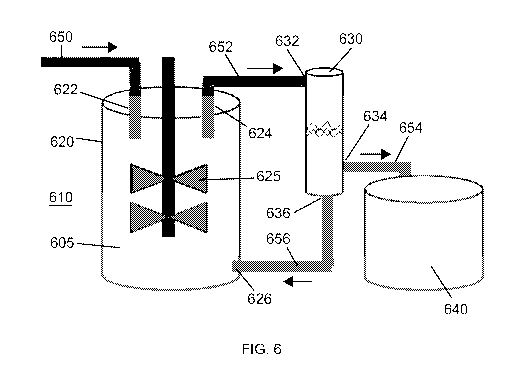
[0082] Figure 6 illustrates an exemplary processing system of the present
disclosure, comprising a bioreactor 610 and a filtering device 630. The system
is set up
for use as a perfusion bioreactor. The bioreactor 610 includes a reaction
vessel 620
having a feed inlet 622, an outlet 624, and a recycle inlet 626. Media is
added into the
feed inlet 622 by an addition pipe 650. The contents of the reaction vessel
(reference
numeral 605) are mixed with an agitator 625. The desired product (e.g.
recombinant
proteins, viruses, exosomes, or additional cells) is continuously produced by
the cells
located within the vessel 620, and are present in the media of the bioreactor.
The
product and the cells in the perfusion bioreactor are drawn from the reaction
vessel
through pipe 652, and enter the acoustophoretic filtering device 630 through
inlet 632.
There, the desired product is separated from the cells through the use of
multi-
dimensional standing waves. The desired product can be drawn off through a
product
outlet 634 and pipe 654 into a containment vessel 640. The cells are returned
to the
perfusion bioreactor after separation, passing from recycle outlet 636 of the
filtering
device through pipe 656 to recycle inlet 626 of the reaction vessel, which
form a recycle
path. The 3-D standing waves of the acoustophoresis device allow for high
throughput
of the perfusion reactor due to the increased lateral trapping force of the 3-
D standing
waves. It is noted that although the reaction vessel outlet 624 is depicted at
the top of
the vessel and the recycle inlet 626 is depicted at the bottom of the vessel,
that this
arrangement can be reversed if desired. This may depend on the desired product
to be
obtained.
[0083] In additional embodiments, it is particularly contemplated that the
filtering
device 630 is in the form of a flexible bag or pouch. Such a filtering device
is illustrated
in Figure 19. The interior volume of the flexible bag 700 operates as the flow
chamber.
CA 03034208 2019-02-15
WO 2018/034655 PCT/US2016/047217
The flexible bag includes an inlet 702 and an outlet 704. Opposite surfaces of
the
flexible bag can be stiff. One surface includes an ultrasonic transducer 710,
and the
opposite surface includes a reflector 712 opposite the transducer, so that a
multi-
dimensional acoustic standing wave can be generated within the bag.
[0084] Referring to both Figure 6 and Figure 7, cell culture media and
cells are
drawn from the reaction vessel through pipe 652, and enter the flexible bag
700 through
inlet 702. The multi-dimensional acoustic standing wave traps the desired
product (i.e.
cells). The cell culture media and other material exit through the outlet 704
through pipe
656 back to recycle inlet 626 of the reaction vessel. Eventually, as the bag
fills up with
concentrated cells, the fluid flow through the bag 700 is stopped. The bag
filled with
concentrated cells can then be taken out of the recycle path between the
product outlet
634 and the recycle inlet 626 of the reaction vessel. The concentrated cells
are then
recovered from the bag.
[0085] In other embodiments, it is particularly contemplated that a
flexible bag or
pouch is used within the flow chamber of the filtering device 630 for the
capture of cells.
This flexible bag or pouch is similar to the bag 700 of Figure 19, but does
not have the
ultrasonic transducer and reflector attached thereto. Cell culture media and
cells are
drawn from the reaction vessel through pipe 652, and enter the acoustophoretic
filtering
device 630 through inlet 632. The flexible bag itself contains an inlet and an
outlet, and
the acoustophoretic filtering device acts as a housing for the bag. The multi-
dimensional acoustic standing wave traps the desired product (i.e. cells). The
cell
culture media and other material exit through the outlet of the bag and out
through
recycle outlet 636 of the filtering device through pipe 656 to recycle inlet
626 of the
reaction vessel, which form a recycle path.
[0086] Within the flexible bag, as the quantity of trapped cells increases,
the cells
form larger clusters that will fall out of the acoustic standing wave at a
critical size due to
gravity forces. The clusters fall to the bottom of the bag. Eventually, as the
bag fills up
with concentrated cells, the fluid flow through the filtering device 630 is
stopped. The
bag filled with concentrated cells can then be removed and a new bag placed
within the
filtering device 630. Referring to Figure 6, the filtering device inlet 632
would probably
be near the middle of the filtering device 630, and the recycle outlet 636
would probably
CA 03034208 2019-02-15
WO 2018/034655 PCT/US2016/047217
21
be located at the top of the filtering device, with the concentrated cells
falling to the
bottom of the flexible bag to be collected. No product outlet 634 or
containment vessel
640 would be needed to collect the product, which would be collected in the
flexible bag
that is subsequently removed from the flow chamber of the filtering device
630.
[0087] It may be helpful now to describe the ultrasonic transducer(s) used
in the
acoustophoretic filtering device in more detail. Figure 7 is a cross-sectional
diagram of
a conventional ultrasonic transducer. This transducer has a wear plate 50 at a
bottom
end, epoxy layer 52, ceramic crystal 54 (made of, e.g. Lead Zirconate Titanate
(PZT)),
an epoxy layer 56, and a backing layer 58. On either side of the ceramic
crystal, there is
an electrode: a positive electrode 61 and a negative electrode 63. The epoxy
layer 56
attaches backing layer 58 to the crystal 54. The entire assembly is contained
in a
housing 60 which may be made out of, for example, aluminum. An electrical
adapter 62
provides connection for wires to pass through the housing and connect to leads
(not
shown) which attach to the crystal 54. Typically, backing layers are designed
to add
damping and to create a broadband transducer with uniform displacement across
a
wide range of frequency and are designed to suppress excitation at particular
vibrational
eigen-modes. Wear plates are usually designed as impedance transformers to
better
match the characteristic impedance of the medium into which the transducer
radiates.
[0088] Figure 8 is a photo of a wear plate 50 with a bubble 64 where the
wear plate
has pulled away from the ceramic crystal surface due to the oscillating
pressure and
heating.
[0089] Figure 9 is a cross-sectional view of an ultrasonic transducer 81 of
the
present disclosure, which is used in the acoustophoretic filtering devices of
the present
disclosure. Transducer 81 has an aluminum housing 82. A PZT crystal 86 defines
the
bottom end of the transducer, and is exposed from the exterior of the housing.
The
crystal is supported on its perimeter by a small elastic layer 98, e.g.
silicone or similar
material, located between the crystal and the housing. Put another way, no
wear layer
is present.
[0090] Screws (not shown) attach an aluminum top plate 82a of the housing
to the
body 82b of the housing via threads 88. The top plate includes a connector 84
to pass
power to the PZT crystal 86. The bottom and top surfaces of the PZT crystal 86
are
CA 03034208 2019-02-15
WO 2018/034655 PCT/US2016/047217
22
each connected to an electrode (positive and negative), such as silver or
nickel. A
wrap-around electrode tab 90 connects to the bottom electrode and is isolated
from the
top electrode. Electrical power is provided to the PZT crystal 86 through the
electrodes
on the crystal, with the wrap-around tab 90 being the ground connection point.
Note that
the crystal 86 has no backing layer or epoxy layer as is present in Figure 5.
Put another
way, there is an air gap 87 in the transducer between aluminum top plate 82a
and the
crystal 86 (i.e. the air gap is completely empty). A minimal backing 58 and/or
wear plate
50 may be provided in some embodiments, as seen in Figure 10.
[0091]
The transducer design can affect performance of the system. A typical
transducer is a layered structure with the ceramic crystal bonded to a backing
layer and
a wear plate. Because the transducer is loaded with the high mechanical
impedance
presented by the standing wave, the traditional design guidelines for wear
plates, e.g.,
half wavelength thickness for standing wave applications or quarter wavelength
thickness for radiation applications, and manufacturing methods may not be
appropriate. Rather, in one embodiment of the present disclosure the
transducers,
there is no wear plate or backing, allowing the crystal to vibrate in one of
its eigenmodes
with a high Q-factor. The vibrating ceramic crystal/disk is directly exposed
to the fluid
flowing through the flow chamber.
[0092]
Removing the backing (e.g. making the crystal air backed) also permits the
ceramic crystal to vibrate at higher order modes of vibration with little
damping (e.g.
higher order modal displacement). In a transducer having a crystal with a
backing, the
crystal vibrates with a more uniform displacement, like a piston. Removing the
backing
allows the crystal to vibrate in a non-uniform displacement mode. The higher
order the
mode shape of the crystal, the more nodal lines the crystal has. The higher
order modal
displacement of the crystal creates more trapping lines, although the
correlation of
trapping line to node is not necessarily one to one, and driving the crystal
at a higher
frequency will not necessarily produce more trapping lines.
[0093]
In some embodiments, the crystal may have a backing that minimally affects
the Q-factor of the crystal (e.g. less than 5%). The backing may be made of a
substantially acoustically transparent material such as balsa wood, foam, or
cork which
allows the crystal to vibrate in a higher order mode shape and maintains a
high Q-factor
CA 03034208 2019-02-15
WO 2018/034655 PCT/US2016/047217
23
while still providing some mechanical support for the crystal. The backing
layer may be
a solid, or may be a lattice having holes through the layer, such that the
lattice follows
the nodes of the vibrating crystal in a particular higher order vibration
mode, providing
support at node locations while allowing the rest of the crystal to vibrate
freely. The goal
of the lattice work or acoustically transparent material is to provide support
without
lowering the Q-factor of the crystal or interfering with the excitation of a
particular mode
shape.
[0094]
Placing the crystal in direct contact with the fluid also contributes to the
high
Q-factor by avoiding the dampening and energy absorption effects of the epoxy
layer
and the wear plate. Other embodiments may have wear plates or a wear surface
to
prevent the PZT, which contains lead, contacting the host fluid. This may be
desirable
in, for example, biological applications such as separating blood. Such
applications
might use a wear layer such as chrome, electrolytic nickel, or electroless
nickel.
Chemical vapor deposition could also be used to apply a layer of poly(p-
xylylene) (e.g.
Parylene) or other polymer. Organic and biocompatible coatings such as
silicone or
polyurethane are also usable as a wear surface.
[0095]
In some embodiments, the ultrasonic transducer has a 1 inch diameter and a
nominal 2 MHz resonance frequency. Each transducer can consume about 28 W of
power for droplet trapping at a flow rate of 3 GPM. This power usage
translates to an
energy cost of 0.25 kW hr/ m3. This measure is an indication of the very low
cost of
energy of this technology. Desirably, each transducer is powered and
controlled by its
own amplifier. In other embodiments, the ultrasonic transducer uses a square
crystal,
for example with 1"x1" dimensions. Alternatively, the ultrasonic transducer
can use a
rectangular crystal, for example with 1"x2.5" dimensions.
Power dissipation per
transducer was 10 W per 1"x1" transducer cross-sectional area and per inch of
acoustic
standing wave span in order to get sufficient acoustic trapping forces. For a
4" span of
an intermediate scale system, each 1"x1" square transducer consumes 40 W. The
larger 1"x2.5" rectangular transducer uses 100W in an intermediate scale
system. The
array of three 1"x1" square transducers would consume a total of 120 W and the
array
of two 1"x2.5" transducers would consume about 200 W. Arrays of closely spaced
transducers represent alternate potential embodiments of the technology.
Transducer
CA 03034208 2019-02-15
WO 2018/034655 PCT/US2016/047217
24
size, shape, number, and location can be varied as desired to generate desired
three-
dimensional acoustic standing wave patterns.
[0096]
The size, shape, and thickness of the transducer determine the transducer
displacement at different frequencies of excitation, which in turn affects
separation
efficiency. Typically, the transducer is operated at frequencies near the
thickness
resonance frequency (half wavelength). Gradients in transducer displacement
typically
result in more trapping locations for the cells/biomolecules.
Higher order modal
displacements generate three-dimensional acoustic standing waves with strong
gradients in the acoustic field in all directions, thereby creating equally
strong acoustic
radiation forces in all directions, leading to multiple trapping lines, where
the number of
trapping lines correlate with the particular mode shape of the transducer.
[0097]
To investigate the effect of the transducer displacement profile on acoustic
trapping force and separation efficiencies, an experiment was repeated ten
times using
a 1"x1" square transducer, with all conditions identical except for the
excitation
frequency. Ten consecutive acoustic resonance frequencies, indicated by
circled
numbers 1-9 and letter A on Figure 11, were used as excitation frequencies.
The
conditions were experiment duration of 30 min, a 1000 ppm oil concentration of
approximately 5-micron SAE-30 oil droplets, a flow rate of 500 ml/min, and an
applied
power of 20W. Oil droplets were used because oil is denser than water, and can
be
separated from water using acoustophoresis.
[0098]
Figure 11 shows the measured electrical impedance amplitude of a square
transducer as a function of frequency in the vicinity of the 2.2 MHz
transducer
resonance. The minima in the transducer electrical impedance correspond to
acoustic
resonances of the water column and represent potential frequencies for
operation.
Numerical modeling has indicated that the transducer displacement profile
varies
significantly at these acoustic resonance frequencies, and thereby directly
affects the
acoustic standing wave and resulting trapping force. Since the transducer
operates
near its thickness resonance, the displacements of the electrode surfaces are
essentially out of phase. The typical displacement of the transducer
electrodes is not
uniform and varies depending on frequency of excitation. As an example, at one
frequency of excitation with a single line of trapped oil droplets, the
displacement has a
CA 03034208 2019-02-15
WO 2018/034655 PCT/US2016/047217
single maximum in the middle of the electrode and minima near the transducer
edges.
At another excitation frequency, the transducer profile has multiple maxima
leading to
multiple trapped lines of oil droplets. Higher order transducer displacement
patterns
result in higher trapping forces and multiple stable trapping lines for the
captured oil
droplets.
[0099]
As the oil-water emulsion passed by the transducer, the trapping lines of oil
droplets were observed and characterized.
The characterization involved the
observation and pattern of the number of trapping lines across the fluid
channel, as
shown in Figure 12, for seven of the ten resonance frequencies identified in
Figure 11.
Different displacement profiles of the transducer can produce different (more)
trapping
lines in the standing waves, with more gradients in displacement profile
generally
creating higher trapping forces and more trapping lines.
[0100]
Figure 13 is a numerical model showing a pressure field that matches the 9
trapping line pattern. The numerical model is a two-dimensional model; and
therefore
only three trapping lines are observed. Two more sets of three trapping lines
exist in
the third dimension perpendicular to the plane of the page.
[0101]
In the present system examples, the system is operated at a voltage such
that the particles (i.e. biomolecules or cells) are trapped in the ultrasonic
standing wave,
i.e., remain in a stationary position. The particles are collected in along
well defined
trapping lines, separated by half a wavelength. Within each nodal plane, the
particles
are trapped in the minima of the acoustic radiation potential. The axial
component of the
acoustic radiation force drives particles with a positive contrast factor to
the pressure
nodal planes, whereas particles with a negative contrast factor are driven to
the
pressure anti-nodal planes. The radial or lateral component of the acoustic
radiation
force is the force that traps the particle. It therefore, for particle
trapping, is larger than
the combined effect of fluid drag force and gravitational force. In systems
using typical
transducers, the radial or lateral component of the acoustic radiation force
is typically
several orders of magnitude smaller than the axial component of the acoustic
radiation
force. However, the lateral force generated by the transducers of the present
disclosure
can be significant, on the same order of magnitude as the axial force
component, and is
sufficient to overcome the fluid drag force at linear velocities of up to 1
cm/s.
CA 03034208 2019-02-15
WO 2018/034655 PCT/US2016/047217
26
[0102] The lateral force can be increased by driving the transducer in
higher order
mode shapes, as opposed to a form of vibration where the crystal effectively
moves as
a piston having a uniform displacement. The acoustic pressure is proportional
to the
driving voltage of the transducer. The electrical power is proportional to the
square of
the voltage. The transducer is typically a thin piezoelectric plate, with
electric field in the
z-axis and primary displacement in the z-axis. The transducer is typically
coupled on
one side by air (i.e. the air gap within the transducer) and on the other side
by the fluid
of the cell culture media. The types of waves generated in the plate are known
as
composite waves. A subset of composite waves in the piezoelectric plate is
similar to
leaky symmetric (also referred to as compressional or extensional) Lamb waves.
The
piezoelectric nature of the plate typically results in the excitation of
symmetric Lamb
waves. The waves are leaky because they radiate into the water layer, which
result in
the generation of the acoustic standing waves in the water layer. Lamb waves
exist in
thin plates of infinite extent with stress free conditions on its surfaces.
Because the
transducers of this embodiment are finite in nature, the actual modal
displacements are
more complicated.
[0103] Figure 14 shows the typical variation of the in-plane displacement
(x-
displacement) and out-of-plane displacement (y-displacement) across the
thickness of
the plate, the in-plane displacement being an even function across the
thickness of the
plate and the out-of-plane displacement being an odd function. Because of the
finite
size of the plate, the displacement components vary across the width and
length of the
plate. In general, a (m,n) mode is a displacement mode of the transducer in
which there
are m undulations in transducer displacement in the width direction and n
undulations in
the length direction, and with the thickness variation as described in Figure
14. The
maximum number of m and n is a function of the dimension of the crystal and
the
frequency of excitation.
[0104] The transducers are driven so that the piezoelectric crystal
vibrates in higher
order modes of the general formula (m, n), where m and n are independently 1
or
greater. Generally, the transducers will vibrate in higher order modes than
(2,2). Higher
order modes will produce more nodes and antinodes, result in three-dimensional
standing waves in the fluid layer, characterized by strong gradients in the
acoustic field
CA 03034208 2019-02-15
WO 2018/034655 PCT/US2016/047217
27
in all directions, not only in the direction of the standing waves, but also
in the lateral
directions. As a consequence, the acoustic gradients result in stronger
trapping forces
in the lateral direction.
[0105] In embodiments, the pulsed voltage signal driving the transducer can
have a
sinusoidal, square, sawtooth, or triangle waveform; and have a frequency of
500 kHz to
MHz. The pulsed voltage signal can be driven with pulse width modulation,
which
produces any desired waveform. The pulsed voltage signal can also have
amplitude or
frequency modulation start/stop capability to eliminate streaming.
[0106] The transducer(s) is/are used to create a pressure field that
generates forces
of the same order of magnitude both orthogonal to the standing wave direction
and in
the standing wave direction. When the forces are roughly the same order of
magnitude,
particles of size 0.1 microns to 300 microns will be moved more effectively
towards
regions of agglomeration ("trapping lines"). Because of the equally large
gradients in the
orthogonal acoustophoretic force component, there are "hot spots" or particle
collection
regions that are not located in the regular locations in the standing wave
direction
between the transducer and the reflector. Hot spots are located in the maxima
or
minima of acoustic radiation potential. Such hot spots represent particle
collection
locations which allow for better wave transmission between the transducer and
the
reflector during collection and stronger inter-particle forces, leading to
faster and better
particle agglomeration.
[0107] Figure 15 and Figure 16 are exploded views showing the various parts
of
acoustophoretic separators. Figure 15 has only one separation chamber, while
Figure
16 has two separation chambers.
[0108] Referring to Figure 15, fluid enters the separator 190 through a
four-port inlet
191. A transition piece 192 is provided to create plug flow through the
separation
chamber 193. A transducer 40 and a reflector 194 are located on opposite walls
of the
separation chamber. Fluid then exits the separation chamber 193 and the
separator
through outlet 195.
[0109] Figure 16 has two separation chambers 193. A system coupler 196 is
placed
between the two chambers 193 to join them together.
CA 03034208 2019-02-15
WO 2018/034655 PCT/US2016/047217
28
[0110] Acoustophoretic separation has been tested on different lines of
Chinese
hamster ovary (CHO) cells. In one experiment, a solution with a starting cell
density of
8.09x10⁶ cells/mL, a turbidity of 1,232 NTU, and cell viability of roughly 75%
was
separated using a system as depicted in Figure 15. The transducers were 2 MHz
crystals, run at approximately 2.23 MHz, drawing 24-28 Watts. A flow rate of
25 mL/min
was used. The result of this experiment is shown in Figure 17.
[0111] In another experiment, a solution with a starting cell density of
8.09x10⁶
cells/mL, a turbidity of 1,232 NTU, and cell viability of roughly 75% was
separated. This
CHO cell line had a bi-modal particle size distribution (at size 12 pm and 20
pm). The
result is shown in Figure 18.
[0112] Figure 17 and Figure 18 were produced by a Beckman Coulter Cell
Viability
Analyzer. Other tests revealed that frequencies of 1 MHz and 3 MHz were not as
efficient as 2 MHz at separating the cells from the fluid.
[0113] In other tests at a flow rate of 10 L/hr, 99% of cells were captured
with a
confirmed cell viability of more than 99%. Other tests at a flow rate of 50
mL/min (i.e. 3
L/hr) obtained a final cell density of 3x10⁶ cells/mL with a viability of
nearly 100% and
little to no temperature rise. In yet other tests, a 95% reduction in
turbidity was obtained
at a flow rate of 6 L/hr.
[0114] Further testing was performed using yeast as a simulant for CHO for
the
biological applications. For these tests, at a flow rate of 15 L/hr, various
frequencies
were tested as well as power levels. Table 1 shows the results of the testing.
Table 1: 2.5" x 4" System results at 15 L/hr Flow rate
Frequency (MHz) 30 Watts 37 Watts 45 Watts
2.2211 93.9 81.4 84.0
2.2283 85.5 78.7 85.4
2.2356 89.1 85.8 81.0
2.243 86.7 79.6
[0115] In biological applications, it is contemplated that all of the parts
of the system
(e.g. the flow chamber, tubing leading to and from the bioreactor or filtering
device, the
sleeve containing the ultrasonic transducer and the reflector, the temperature-
regulating
jacket, etc.) can be separated from each other and be disposable. Avoiding
centrifuges
CA 03034208 2019-02-15
WO 2018/034655 PCT/US2016/047217
29
and filters allows better separation of the CHO cells without lowering the
viability of the
cells. The transducers may also be driven to create rapid pressure changes to
prevent
or clear blockages due to agglomeration of CHO cells. The frequency of the
transducers
may also be varied to obtain optimal effectiveness for a given power.
[0116] The present disclosure has been described with reference to
exemplary
embodiments. Modifications and alterations will occur to others upon reading
and
understanding the preceding detailed description. It is intended that the
present
disclosure be construed as including all such modifications and alterations
insofar as
they come within the scope of the appended claims or the equivalents thereof.