Note: Descriptions are shown in the official language in which they were submitted.
CA 03034341 2019-02-19
WO 2018/041924 PCT/EP2017/071821
Susceptor assembly and aerosol-generating article comprising
the same
The invention relates to a susceptor assembly for heating
an aerosol-forming substrate and an aerosol-generating
article comprising such a susceptor assembly.
Systems are known, where two different susceptor
materials typically having different Curie temperatures are
used to heat and control heating of an aerosol-forming
substrate of an aerosol-generating article accommodated in an
electronic smoking device. For example, in the international
patent publication W02015/177294 two strip-shaped susceptor
materials are in intimate physical contact forming a
susceptor assembly. One susceptor material is selected having
a Curie temperature which corresponds to a predefined maximum
heating temperature of the other susceptor material. Thus,
the one susceptor material is optimized with regard to
temperature control while the other susceptor material is
optimized with regard to heating. However, the manufacture of
such susceptor assemblies is not very cost efficient.
Thus, it would be desirable to have a susceptor assembly
providing heating as well as temperature control, and that
may be manufactured in a cost efficient and preferably simple
manufacturing process.
According to the invention, there is provided a susceptor
assembly for heating an aerosol-forming substrate. The
susceptor assembly comprises a first susceptor material
having an elongate shape and being coated with a coating
material. The susceptor assembly further comprises a second
susceptor material, which is provided in the form of a
plurality of susceptor particles having a second Curie
CA 03034341 2019-02-19
WO 2018/041924 PCT/EP2017/071821
2
temperature below 500 degree Celsius. The susceptor particles
are embedded in the coating material which coats the first
susceptor material. The coating material may entirely or only
partly cover the first susceptor material.
By providing a first and a second susceptor material,
preferably having first and second Curie temperatures
distinct from one another, the heating of the aerosol-forming
substrate and the temperature control of the heating may be
separated. While the first susceptor material may be
optimized with regard to heat loss and thus heating
efficiency, the second susceptor material may be optimized in
respect of temperature control and does not need to have
pronounced heating characteristics.
Thus, the plurality of particles that are basically only
provided for temperature control purposes may be present in
small amounts. The characteristic of the particles
additionally allows a distribution of the second susceptor
material over a relatively large area or over the entire
volume of the coating material. Thus, temperature control may
be achieved with small amounts of second susceptor material.
Typical amounts of susceptor particles may range between
1 milligram and 5 milligram, for example between 3 milligram
and 5 milligram.
Advantageously, the second susceptor material is selected
having a Curie temperature, which corresponds to a predefined
maximum heating temperature of the first susceptor material.
The maximum heating temperature may be defined such that a
local burning of surrounding material is avoided.
When a susceptor material reaches its Curie temperature,
the magnetic properties change. At the Curie temperature the
susceptor material changes from a ferromagnetic phase to a
paramagnetic phase. At this point, heating based on energy
CA 03034341 2019-02-19
WO 2018/041924 PCT/EP2017/071821
3
loss due to orientation of ferromagnetic domains stops.
Further heating is then mainly based on eddy current
formation such that a heating process is automatically
reduced upon reaching the Curie temperature of the susceptor
material. Reducing the risk of overheating the aerosol-
forming substrate may thus be supported by the use of
susceptor materials having a Curie temperature, which allows
a heating process due to hysteresis loss only up to a certain
maximum temperature. Preferably, susceptor material and its
Curie temperature are adapted to the composition of the
aerosol-forming substrate to be heated in order to achieve an
optimal temperature and temperature distribution in a tobacco
product for an optimum aerosol generation.
The second Curie temperature of the second susceptor
material is below 500 degree Celsius. Preferably, the second
Curie temperature of the second susceptor material is
selected such that upon being inductively heated an overall
average temperature of an aerosol-forming substrate of an
aerosol-forming substrate element in a corresponding article
does not exceed 240 C. The overall average temperature of the
aerosol-forming substrate here is defined as the arithmetic
mean of a number of temperature measurements in central
regions and in peripheral regions of the aerosol-forming
substrate. Preferably, the second Curie temperature of the
second susceptor material does not exceed 370 C. By this,
local overheating of an aerosol-forming substrate of typical
heat sticks used in electronic devices may be avoided.
The second Curie temperature may be between about
200 degree Celsius and about 450 degree Celsius, preferably
between about 240 degree Celsius and about 400 degree
Celsius, for example about 280 degree Celsius.
CA 03034341 2019-02-19
WO 2018/041924 PCT/EP2017/071821
4
As a general rule, whenever a value is mentioned
throughout this application, this is to be understood such
that the value is explicitly disclosed. However, a value is
also to be understood as not having to be exactly the
particular value due to technical considerations.
Once the second susceptor material has reached its second
Curie temperature, its magnetic properties change. At the
second Curie temperature the second susceptor material
reversibly changes from a ferromagnetic phase to a
paramagnetic phase. During the inductive heating this phase-
change of the second susceptor material may be detected on-
line and the inductive heating may be stopped automatically.
For example a control unit, associated to a power supply
of a device, may be capable of detecting when the second
susceptor material has reached its Curie temperature
(preferably corresponding to the maximum heating temperature
of the first susceptor material) by monitoring the values of
the current absorbed by the inductor.
Thus, an overheating of aerosol-forming substrate the
susceptor assembly is accommodated in may be avoided, even
though the first susceptor material, which is responsible for
the heating of the aerosol-forming substrate, may not have a
Curie temperature at all or may have a first Curie
temperature, which is higher than the predefined maximum
heating temperature. After the inductive heating has been
stopped the second susceptor material cools down until it
reaches a temperature lower than its second Curie temperature
at which it regains its ferromagnetic properties again. This
phase change may again be detected on-line and the inductive
heating may be activated again. The temperature control is
accomplished contactless. A circuitry and electronics is
preferably already integrated in an inductive heating device
CA 03034341 2019-02-19
WO 2018/041924 PCT/EP2017/071821
such that there is no need for any additional circuitry and
electronics.
The first susceptor material, which is preferably
optimized for the heating, preferably has a first Curie
5 temperature, which is higher than the second Curie
temperature and preferably higher than the predefined maximum
heating temperature of the first susceptor material.
The elongate first susceptor has a length dimension that
is greater than its width dimension or its thickness
dimension, for example greater than twice its width dimension
or its thickness dimension. Thus the first susceptor may be
described as an elongate susceptor. The elongate susceptor
basically defines the shape of the susceptor assembly, such
that the assembly also comprises an elongate shape.
Accordingly, a susceptor assembly is arranged substantially
longitudinally within a rod-shaped element of an aerosol-
generating article. This means that the length dimension of
the elongate susceptor or susceptor assembly, respectively,
is arranged to be approximately parallel to a longitudinal
direction of a rod-shaped article, for example within plus or
minus 10 degrees of parallel to the longitudinal direction of
the article. In preferred embodiments, the elongate susceptor
is positioned in a radially central position within the rod
and extends along the longitudinal axis of the rod.
Preferably, the elongate first susceptor is in the form
of a pin, rod, strip or blade. Preferably, the elongate
susceptor has a length between 5 millimeter and
15 millimeter, for example, between 6 mm and 12 mm, or
between 8 mm and 10 mm. A lateral extension of a first
susceptor material may, for example, be between 0.5 mm and
8 mm, preferably between 1 mm and 6 mm, for example 4
millimeter. The elongate susceptor preferably has a width
CA 03034341 2019-02-19
WO 2018/041924 PCT/EP2017/071821
6
between 1 mm and 5 mm and may have a thickness between
0.01 mm and 2 mm, for example between 0.5 mm and 2 mm. In a
preferred embodiment the elongate susceptor may have a
thickness between 10 micrometer and 500 micrometer, or even
more preferably between 10 and 100 micrometer. If the
elongate susceptor has a constant cross-section, for example
a circular cross-section, it has a preferable width or
diameter between 1 millimeter and 5 millimeter. If the
elongate susceptor has the form of a strip or blade, for
example, is made of a sheet-like susceptor material, the
strip or blade preferably has a rectangular shape having a
width preferably between 2 millimeter and 8 millimeter, more
preferably, between 3 mm and 5 mm, for example 4 mm and a
thickness preferably between 0.03 millimeter
and
0.15 millimeter, more preferably between 0.05 mm and 0.09 mm,
for example 0.07 mm.
Preferably, the elongate first susceptor has a length
which is the same or shorter than a length of an aerosol-
forming substrate element, the susceptor assembly is arranged
in. Preferably, the elongate susceptor has a same length as
the aerosol-forming substrate element.
In embodiments wherein the first susceptor material has a
flat or substantially flat shape defining two opposed large
sides, for example wherein the elongate susceptor is a strip
or blade, the coating material is provided on at least one
side of the two opposed large sides of the first susceptor
material. The coating material may be provided on only one or
on both of the two opposed large sides of the first susceptor
material. The coating material may be provided only partly on
one or on both large sides.
The first susceptor material may be entirely coated with
the coating material.
CA 03034341 2019-02-19
WO 2018/041924 PCT/EP2017/071821
7
Preferably, the first susceptor material comprises a
single coating material coating.
Preferably, the plurality of particles of the second
susceptor material is homogeneously distributed in the
coating material. By this, a temperature control in the
coating material may be achieved rather uniformly over the
extent of the coating material where it is coating the first
susceptor material.
The susceptor particles may have sizes in a range of
about 5 micrometer to about 100 micrometer, preferably in a
range of about 10 micrometer to about 80 micrometer, for
example have sizes between 20 micrometer and 50 micrometer.
The size of particles is herein understood as the
equivalent spherical diameter. Since the particles may be of
irregular shape, the equivalent spherical diameter defines
the diameter of a sphere of equivalent volume as a particle
of irregular shape.
The susceptor particles may comprise or may be made of a
sintered material. Sintered material provides a wide variety
of electric, magnetic and thermal properties. Sintered
material may be of ceramic, metallic or plastic nature.
Preferably, for susceptor particles metallic alloys are used.
Preferably, sinter material for the particles used for the
susceptor assembly according to the invention has a high
thermal conductivity and a high magnetic permeability.
The susceptor particles as well as the first susceptor
material may comprise an outer surface which is chemically
inert. A chemically inert surface prevents the particles to
take place in a chemical reaction or possibly serve as
catalyst to initialize an undesired chemical reaction with
the coating material the particles are embedded in, in
particular with an aerosol-forming substrate coating. An
CA 03034341 2019-02-19
WO 2018/041924 PCT/EP2017/071821
8
inert chemical outer surface may be a chemically inert
surface of the susceptor material itself. An inert chemical
outer surface may also be a chemically inert cover layer that
encapsulates the susceptor particles within the chemically
inert cover. A cover material may withstand temperatures as
high as the particles are heated. An encapsulation step may
be integrated into a sinter process when the particles are
manufactured. If the coating material is not itself an
aerosol-forming substrate coating, the coating material may
be chemically inert with respect to the coating material and
the aerosol-forming substrate to be heated by the susceptor
assembly. Chemically inert is herein understood with respect
to chemical substances generated by heating the aerosol-
forming substrate, in particular, a tobacco product.
The particles of the second susceptor material may be
made of ferrite. Ferrite is a ferromagnet with a high
magnetic permeability and especially suitable as susceptor
material. Main component of ferrite is iron. Other metallic
components, for example, zinc, nickel, manganese, or non-
metallic components, for example silicon, may be present in
varying amounts. Ferrite is a relatively inexpensive,
commercially available material. Ferrite is available in
particle form in the size ranges of the particles as
mentioned herein. Preferably, the particles are a fully
sintered ferrite powder, such as for example FP350 available
by Powder Processing Technology LLC, USA.
The coating of the first susceptor material with a
coating material provides a very close and direct physical
contact between the coating material and the first susceptor
material. Heat transfer from the first susceptor material to
the coating material is optimized. The close contact leads to
a fast heating up of the coating material. Thus, if the
CA 03034341 2019-02-19
WO 2018/041924 PCT/EP2017/071821
9
coating material is a tobacco or tobacco material containing
coating material or an aerosol-forming substrate, a fast
heating up of the aerosol-forming substrate in the coating
may be achieved and by this a fast aerosol-formation from the
aerosol-forming substrate of the coating material. This may
lead to a short time to a first puff of an aerosol-generating
device a susceptor assembly according to the invention is
used with.
The coating material may basically be selected from any
material suitable for the application in aerosol-generating
devices. Coating materials may be any material that may
withstand the heating temperatures in these devices, that may
at these temperatures retain the susceptor particles in
thermal proximity with the first susceptor material, and that
are suitable for coating a susceptor material. A coating
material may, for example, comprise or consist of a resin,
glue or gel where the plurality of first susceptor particles
is embedded in.
A coating material may be a substrate capable of forming
aerosol or not forming an aerosol but retaining the susceptor
particles. Such a substrate may, for example, be an aerosol-
forming resin, a non-aerosol-forming resin, an aerosol-
forming glue, a non-aerosol-forming glue or an aerosol-
forming gel or a non-aerosol-forming gel.
A non-aerosol-forming coating is defined to not form an
aerosol in the temperature range used in the aerosol-
generating device, for example below 500 degree Celsius.
Preferably, a coating material is an aerosol-forming
substrate, capable of forming an aerosol, preferably in the
same temperature range as the aerosol-forming substrate to be
heated by the coated first susceptor material.
Preferably, a coating material not being an aerosol-
CA 03034341 2019-02-19
WO 2018/041924 PCT/EP2017/071821
forming substrate is thermally conductive such that heat
generated in the first susceptor is conducted through the
coating material to a surrounding aerosol-forming substrate.
Thermal conductivity is the property of a material to
5 conduct heat. Heat transfer occurs at a lower rate across
materials of low thermal conductivity than across materials
of high thermal conductivity. The thermal conductivity of a
material may depend on temperature.
Thermally conductive materials as used in the present
10 invention for the coating material may have thermal
conductivities of more than 10 Watt per (meter x Kelvin),
preferably more than 100 Watt per (meter x Kelvin),
for
example between 10 and 500 Watt per (meter x Kelvin).
The coating material may comprise additional components,
for example, flavours, for example tobacco flavour,
stimulating substances, for example, nicotine, or may
comprise antioxidants.
Preferably, the coating material comprises tobacco or
tobacco material to add to a smoking experience when the
coating material is heated.
Preferably, a thickness of an aerosol-forming substrate
coating may be between 80 micrometer and 1 millimeter,
preferably between 100 micrometer and 600 micrometer, for
example between 100 micrometer and 400 micrometer.
Preferably, thicknesses of a coating material not
contributing to aerosol-formation, for example resin
coatings, are smaller. Such coatings may be between
50 micrometer and 120 micrometer, preferably between 60 and
100 micrometer, the thickness may for example be below
100 micrometer,
such as for example between 50 and
90 micrometer.
CA 03034341 2019-02-19
WO 2018/041924 PCT/EP2017/071821
11
Coating of the first susceptor may be performed, for
example, by deposition, dipcoating, spraying, painting or
casting a coating material to an uncoated susceptor material.
These coating methods are standard reliable industrial
processes that allow for mass production of coated objects.
These coating processes also enable high product consistency
in production and repeatability in performance of the
susceptor assembly.
Preferably, an aerosol-forming substrate coating on the
elongate first susceptor material is performed by one of the
above mentioned methods by bringing an aerosol-forming
substrate slurry onto an uncoated elongate first susceptor
material.
Preferably, the coating material is the form of
reconstituted tobacco formed from a tobacco-containing
slurry.
According to the invention there is also provided an
aerosol-generating article comprising a plurality of elements
forming a rod. The plurality of elements comprises an
aerosol-forming substrate element comprising a susceptor
assembly according to the invention and as described herein.
The aerosol-forming substrate element also comprises an
aerosol-forming substrate bulk, wherein the susceptor
assembly is arranged within the aerosol-forming substrate
bulk.
The susceptor assembly may be arranged longitudinally
within the aerosol-forming substrate element. Preferably, the
susceptor assembly is arranged radially centrally within the
aerosol-forming substrate element.
The aerosol-forming substrate bulk may comprise a
gathered sheet of aerosol-forming substrate. Preferably, the
CA 03034341 2019-02-19
WO 2018/041924 PCT/EP2017/071821
12
aerosol-forming substrate bulk comprises a gathered sheet of
homogenised tobacco material.
Aerosol-forming substrate as bulk or coating is a solid
aerosol-forming substrate. The aerosol-forming substrate may
comprise a tobacco-containing material containing volatile
tobacco flavour compounds, which are released from the
substrate upon heating. Alternatively, the aerosol-forming
substrate may comprise a non-tobacco material. The aerosol-
forming substrate may further comprise an aerosol former.
Examples of suitable aerosol formers are glycerine and
propylene glycol.
The aerosol-forming substrate bulk may comprise, for
example, one or more of: powder, granules, pellets, shreds,
spaghetti strands, strips or sheets containing one or more
of: herb leaf, tobacco leaf, fragments of tobacco ribs,
reconstituted tobacco, homogenised tobacco, extruded tobacco
and expanded tobacco. The aerosol-forming substrate bulk may
be in loose form, or may be provided in a suitable container
or cartridge. For example, the aerosol-forming material of
the aerosol-forming substrate bulk may be contained within a
paper or other wrapper and have the form of a plug. Where an
aerosol-forming substrate bulk is in the form of a wrapped
plug, the entire plug, including the coated first susceptor
material including the second susceptor particles in the
coating and including any wrapper forms the aerosol-forming
substrate element.
Optionally, the aerosol-forming substrate may contain
additional tobacco or non-tobacco volatile flavour compounds,
to be released upon heating of the aerosol-forming substrate.
The solid aerosol-forming substrate bulk may also contain
capsules that, for example, include the additional tobacco or
non-tobacco volatile flavour compounds and such capsules may
CA 03034341 2019-02-19
WO 2018/041924 PCT/EP2017/071821
13
melt during heating of the solid aerosol-forming substrate
bulk.
The aerosol-forming substrate bulk may comprise one or
more sheets of homogenised tobacco material that has been
gathered into a rod, circumscribed by a wrapper, and cut to
provide individual plugs of aerosol-forming substrate. Into
this or these gathered, rod-shaped sheets the susceptor
assembly is introduced before, during or after gathering the
sheet into a rod. Preferably, the aerosol-forming substrate
bulk comprises a crimped and gathered sheet of homogenised
tobacco material.
The aerosol-forming substrate element may be
substantially cylindrical in shape. The aerosol-forming
substrate element may be substantially elongate. The aerosol-
forming substrate element may also have a length and a
circumference substantially perpendicular to the length.
Further, the aerosol-forming substrate element may have a
length of 10 millimeter. Alternatively, the aerosol-forming
substrate element may have a length of 12 millimeter.
Further, the diameter of the aerosol-forming substrate
element may be between 5 millimeter and 12 millimeter.
Tobacco containing slurry and a tobacco sheet forming the
aerosol-forming substrate bulk as well as a coating made from
the tobacco containing slurry comprises tobacco particles,
fiber particles, aerosol former, binder and for example also
flavours.
Preferably, the aerosol-forming tobacco substrate bulk is
a tobacco sheet, preferably crimped, comprising tobacco
material, fibers, binder and aerosol former. Preferably, the
tobacco sheet is a cast leaf. Cast leaf is a form of
reconstituted tobacco that is formed from a slurry including
CA 03034341 2019-02-19
WO 2018/041924 PCT/EP2017/071821
14
tobacco particles, fiber particles, aerosol former, binder
and for example also flavours.
Preferably, a coating of coating material is a form of
reconstituted tobacco that is formed from the tobacco
containing slurry.
Tobacco particles may be of the form of a tobacco dust
having particles in the order of 30 micrometers to
250 micrometers, preferably in the order of 30 micrometers to
80 micrometers or 100 micrometers to 250 micrometers,
depending on the desired coating thickness or an a desired
sheet thickness and casting gap, where the casting gap
typically defined the thickness of the sheet.
Fiber particles may include tobacco stem materials,
stalks or other tobacco plant material, and other cellulose-
based fibers such as wood fibers having a low lignin content.
Fiber particles may be selected based on the desire to
produce a sufficient tensile strength for the coating or
sheet versus a low inclusion rate, for example, an inclusion
rate between approximately 2 percent
to 15 percent.
Alternatively, fibers, such as vegetable fibers, may be used
either with the above fiber particles or in the alternative,
including hemp and bamboo.
Aerosol formers included in the slurry for forming the
cast leaf and the coating may be chosen based on one or more
characteristics. Functionally, the aerosol former provides a
mechanism that allows it to be volatilized and convey
nicotine or flavouring or both in an aerosol when heated
above the specific volatilization temperature of the aerosol
former. Different aerosol formers typically vaporize at
different temperatures. An aerosol former may be chosen based
on its ability, for example, to remain stable at or around
room temperature but able to volatize at a higher
CA 03034341 2019-02-19
WO 2018/041924 PCT/EP2017/071821
temperature, for example, between 40 degree Celsius and
450 degree Celsius. The aerosol former may also have
humectant type properties that help maintain a desirable
level of moisture in an aerosol-forming substrate when the
5 substrate is composed of a tobacco-based product including
tobacco particles. In particular, some aerosol formers are
hygroscopic material that function as a humectant, that is, a
material that helps keep a substrate containing the humectant
moist.
10 One or more aerosol former may be combined to take
advantage of one or more properties of the combined aerosol
formers. For example, triacetin may be combined with glycerol
and water to take advantage of the triacetin's ability to
convey active components and the humectant properties of the
15 glycerol.
Aerosol formers may be selected from the polyols, glycol
ethers, polyol ester, esters, and fatty acids and may
comprise one or more of the following compounds: glycerol,
erythritol, 1,3-butylene glycol, tetraethylene glycol,
triethylene glycol, triethyl citrate, propylene carbonate,
ethyl laurate, triacetin, meso-Erythritol, a diacetin
mixture, a diethyl suberate, triethyl citrate, benzyl
benzoate, benzyl phenyl acetate, ethyl vanillate, tributyrin,
lauryl acetate, lauric acid, myristic acid, and propylene
glycol.
A typical process to produce a cast leaf or a slurry for
an aerosol-forming substrate coating includes the step of
preparing the tobacco. For this, tobacco is shredded. The
shredded tobacco is then blended with other kinds of tobacco
and grinded. Typically, other kinds of tobacco are other
types of tobacco such as Virginia or Burley, or may for
example also be differently treated tobacco. The blending and
CA 03034341 2019-02-19
WO 2018/041924 PCT/EP2017/071821
16
grinding steps may be switched. The fibers are prepared
separately and preferably such as to be used for the slurry
in the form of a solution. Since fibers are mainly present in
the slurry for providing stability to a cast leaf or a
coating, the amount of fibers may be reduced or fibers may
even be omitted in a coating due to the aerosol-forming
substrate coating being stabilized by the first susceptor
material.
If present, the fiber solution and the prepared tobacco
are then mixed, preferably together with the susceptor
particles. The slurry may then be transferred to a coating
device, for example a sheet forming apparatus or deposition
device.
After coating, the aerosol-forming substrate is then
dried, preferably by heat and cooled after drying.
The susceptor particles may also be applied to the slurry
after having been brought into the form of a sheet or after
having coated the first susceptor material, but before the
sheet or coating is dried. By this, the susceptor particles
are not homogeneously distributed inside the coating material
but distributed on the surface of the coating.
Preferably, the tobacco containing slurry comprises
homogenized tobacco material and comprises glycerol or
propylene glycol as aerosol former. Preferably, the aerosol-
forming substrate bulk and aerosol-forming substrate coating
is made of a tobacco containing slurry as described above.
Advantageously, an aerosol-forming substrate coating the
first susceptor or any other coating materials comprising
volatile substances are porous to allow volatilized
substances to leave the substrate. Due to the small thickness
of the coating and its close contact to the first susceptor
material also coatings having no or only little porosity may
CA 03034341 2019-02-19
WO 2018/041924 PCT/EP2017/071821
17
be used. A coating with small thickness may, for example, be
chosen to have less porosity than a coating with larger
thickness.
The aerosol-generating article has the form of a rod with
a rod diameter, preferably in the range between about
3 millimeters to about 9 millimeters, more preferably between
about 4 millimeters to about 8 millimeters, for example
7 millimeters. The rod may have a rod length in the range
between about 2 millimeters to about
20 millimeters,
preferably between about 6 millimeters to
about
12 millimeters, for example 10 millimeters. Preferably, the
rod has a circular or oval cross-section. However, the rod
may also have the cross-section of a rectangle or of a
polygon.
Further elements of the plurality of elements of the
aerosol-generating article may, for example, be a mouthpiece
element, a support element and an aerosol-cooling element.
The mouthpiece element may be located at a mouth end or a
downstream end of the aerosol-generating article.
The mouthpiece element may comprise at least one filter
segment. The filter segment may be a cellulose acetate filter
plug made of cellulose acetate tow. A filter segment may be
longitudinally spaced apart from the aerosol-forming
substrate element.
Further features and advantages of the aerosol-generating
article according to the invention have been described
relating to the susceptor assembly according to the invention
and will not be repeated.
According to yet another aspect of the invention there is
provided an aerosol-generating system. The aerosol-generating
system comprises an aerosol generating article according to
the invention and as described herein. The system further
CA 03034341 2019-02-19
WO 2018/041924 PCT/EP2017/071821
18
comprises a power source connected to a load network, the
load network comprising an inductor for being inductively
coupled to the susceptor assembly of the aerosol-generating
article.
The aerosol-generating system may further be equipped
with an electronic control circuitry, which is adapted for a
closed-loop control of the heating of the aerosol-forming
substrate bulk of the aerosol-generating article. Thus, once
the second susceptor material, which performs the function of
temperature control, has reached its second Curie temperature
where it changes its magnetic properties from ferromagnetic
to paramagnetic, the heating may be stopped. When the second
susceptor material has cooled down to a temperature below its
second Curie temperature where its magnetic properties change
back again from paramagnetic to ferromagnetic, the inductive
heating of the aerosol-forming substrate may be automatically
continued again. Thus, with the aerosol-generating system
according to the invention the heating of the aerosol-forming
substrate may be performed at a temperature which oscillates
between the second Curie temperature and that temperature
below the second Curie temperature, at which the second
susceptor material regains its ferromagnetic properties.
The invention is further described with regard to
embodiments, which are illustrated by means of the following
drawings, wherein:
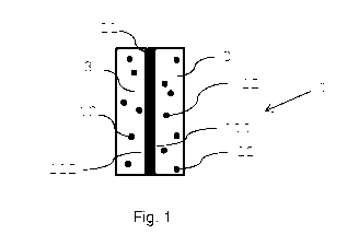
Figs. 1,2 show a side view (Fig. 1) and a top view
(Fig. 2) of a strip-shaped susceptor assembly;
Fig. 3
is a cross sectional or bottom view of an
aerosol-generating substrate element or
aerosol-generating article comprising the
susceptor assembly of Figs. 1 and 2.
CA 03034341 2019-02-19
WO 2018/041924 PCT/EP2017/071821
19
Fig. 1 and Fig. 2 show a side view and a top view of a
susceptor assembly 1. The assembly includes a first susceptor
material 11 having an elongated shape, and a second susceptor
material in the form of susceptor particles 12. The first
susceptor material 11 is coated with a coating material 3 in
which the susceptor particles 12 are embedded. As the second
susceptor material is introduced as a temperature marker, it
is desirable that it is selected among materials having a
Curie temperature below 500 degree Celsius, preferably below
400 degree Celsius.
The first susceptor material 11 has a substantially flat
rectangular shape, defining two opposite large sides 111 and
112. In the example shown the coating material 3 is applied
to both sides 111, 112, but it will be appreciated that the
coating could be applied on one side only and only partially
on one side.
In a preferred embodiment, the coating material 3 is an
aerosol-forming substrate including tobacco material.
Fig. 3 shows a cross section through a rod-shaped
aerosol-forming substrate element 2 or also a frontal section
of an aerosol-generating article comprising the susceptor
assembly 1 of Fig. 1.
The blade-shaped susceptor 11 is coated on its two
longitudinal flat sides with a susceptor particles 12
containing aerosol-forming substrate coating 3. The aerosol-
forming substrate coating 3 is in direct contact with the
first susceptor 11. Preferably, the coating 3 is a dense
tobacco containing coating, advantageously made from a
corresponding tobacco containing slurry. The coating 3 has a
thickness of about 100 micrometer on each large side of the
susceptor blade 11. The coating 3 may serve as aerosol-
forming substrate for a first puff.
CA 03034341 2019-02-19
WO 2018/041924 PCT/EP2017/071821
The coated susceptor 11 is arranged radially centrally
within a gathered cast leaf 22, which is wrapped with a paper
wrapper 61 forming the rod-shaped aerosol-forming substrate
element 2.
5