Note: Descriptions are shown in the official language in which they were submitted.
1
END PIECE FOR A SUNSHADE'S EDGE RAIL AND SUNSHADE
Field
The invention relates to an end piece for a sunshade's edge rail, the end
piece comprising an end
plate, the end plate having a first edge surface, a second edge surface, a
first end surface, and a
second end surface to be placed against an end of the edge rail, the second
end surface having
at least one gripping protrusion adaptable to fit inside the edge rail, and
the end plate having a
first hole for the penetration of a guiding string. The invention relates
further to a sunshade.
Background
Windows, glass opening doors, and balcony glasses are often provided with
sunshades to restrict
the access of solar radiation into room spaces or a balcony. Generally, the
sunshades are either
venetian blinds or so-called pleated blinds, featuring a folding protective
screen which has its top
edge provided with a first edge rail and its bottom edge with a second edge
rail. The edge rails
can be moved along guiding strings co-directional with the edges of an
opening, thereby changing
a shade-giving surface area of the protective screen between the edge rails.
The edge rails are
generally aluminum profiles, which include one or more cavities lengthwise of
the edge rail and
which are closed at the ends thereof with plastic end pieces.
The number of guiding strings is generally at least two, such that the first
guiding string is fixed to
a first edge of the protective screen and the second guiding string to a
second edge of the
protective screen. The guiding strings are attached by a first end thereof to
a first end side of the
.. opening to be covered and by second end thereof to a second end side of the
opening to be
covered. The guiding strings may extend co-directionally with horizontal edges
of the opening to
be covered or co-directionally with vertical edges of the opening. The guiding
strings support the
protective screen by its edges and sustain the protective screen in a
substantially single plane, in
other words prevent deflection of the protective screen. As the width of a
protective screen
increases, the screen's mid-section is often provided with installed support
strings which are
tasked to support and guide a protective screen also at the protective
screen's mid-section.
Support strings are needed especially in pleated blinds intended for balcony
glasses and in blinds
mounted on doors, which are often exposed to wind pressure and airflow. One
pleated blind as
described above is disclosed in publication JPH07166777.
In order for guiding strings to cover as little as possible of a window, door
or balcony glass opening
or a doorway, the guiding strings are often adapted to extend in the closest
possible proximity to
the side edges of an opening to be draped. Such guiding strings are conducted
through the end
CA 3035030 2019-02-26
2
piece of a first edge rail into the edge rail's interior, wherein the string
first runs over a short
distance co-directionally with the edge rail, makes a right-angle turn towards
a second edge rail
and proceeds through holes in the pleats of a protective screen co-
directionally with a side edge
of the opening to be draped into the second edge rail's interior. In the
second edge rail, the guiding
string's passage continues by way of a hole in the second edge rail's end
piece outside of the
edge rail, wherein it deflects again to extend alongside a side edge of the
opening to be draped.
The support strings of wide pleated blinds are conducted to extend into edge
rails and out of edge
rails through holes in the end piece in a substantially identical manner.
In publication US 4825929 A is described an end piece for a sunshade's edge
rail, comprising an
end plate with a first and a second edge surface, a first and a second end
surface, as well as a
hole for the penetration of a guiding string. The second end surface carries a
gripping protrusion
adaptable inside the edge rail.
A problem with the foregoing pleated blinds is that the guiding strings
extending by way of the
edge rails' end pieces are not capable of preventing rotation of the edge
rails around the
longitudinal axes thereof as the edge rails are moved by manual force. The
unintentional rotation
of edge rails while moving the same hampers the operation of a guiding string
mechanism and
causes extra friction that accelerates wear of the guiding strings.
Another problem with pleated blinds is that the passage line of guiding
strings must have its bend
points inside the edge rails installed with support sleeves used for
preventing wear of the guiding
strings. Installation of the support sleeves and threading the guiding strings
therethrough
increases the manufacturing time of pleated blinds.
Summary
It is an objective of the invention to introduce an end piece for a sunshade's
edge rail and a
sunshade, which enable elimination of problems associated with the prior art
and especially with
pleated blinds. The objectives according to the invention are attained with an
end piece and a
sunshade according to embodiments of the invention.
In accordance with a broad aspect, the invention provides an end piece for a
sunshade's edge
rail, the end piece comprising an end plate, the end plate having a first edge
surface, a second
edge surface, a first end surface and a second end surface to be placed
against an end of the
edge rail, the second end surface being provided with at least one gripping
protrusion adaptable
to fit inside the edge rail, the end plate being provided with a first hole
for receiving a guiding
string, wherein the end piece includes a string channel, the string channel
having a width, a first
Date Recue/Date Received 2022-04-07
3
end that opens onto the first edge surface, and a second end that opens onto
the second edge
surface and wherein the first hole opens into the string channel. It is by
virtue of the string channel
that the guiding string included in a sunshade can be extended to the first
hole by way of the string
channel. Between the string channel and the first end surface is provided a
wall, the wall including
a through-going groove. The groove has its first end at a first end of the
string channel and its
second end at a second end of the string channel. The groove has a width which
is substantially
less than the width of the string channel. The groove enables a guiding string
to be placed in the
string channel via the groove through the wall, in other words the guiding
string need not be
threaded into the string channel by way of the string channel's ends. The
groove's width can be
dimensioned to be substantially equal to that of the guiding string. The wall
is provided with a
through-going aperture, the aperture having a width exceeding the width of the
groove and the
aperture being in alignment with the first hole. The aperture facilitates
threading of the guiding
string into the first hole.
In a preferred embodiment for an end piece of the invention, the groove has a
section between
its first end and its second end provided with at least one bend, in other
words, the groove is not
straight over its entire length. In a sunshade installed in place, the guiding
strings are always in a
taut condition, in other words, extending in a straight line. The bend
included in the groove hinders
the undesired departure of a straight-lined guiding string from the string
channel by way of the
groove. Preferably, the bend in the groove is in alignment with the aperture
included in the wall.
In another preferred embodiment for an end piece of the invention, the first
hole has a first
penetrating direction and the end piece has a first gripping protrusion, the
first gripping protrusion
having a through-going string opening, the string opening having a second
penetrating direction.
The second penetrating direction is substantially perpendicular to the first
penetrating direction
and the string opening is located at a distance from the first hole. The
penetrating direction
represents here a center line direction of the hole or the opening.
In another preferred embodiment for an end piece of the invention, the end
plate is further
provided with a second hole for the penetration of a string. The second hole
opens into the string
channel and the end piece is further provided with a second gripping
protrusion, such that the
Date Recue/Date Received 2022-04-07
4
second hole opens alongside or extends through the second gripping protrusion.
The second hole
can be used for passage through the end piece of other strings included in the
sunshade operating
mechanism.
The sunshade according to the invention comprises a first guiding string, a
protective screen with
the protective screen having an edge, and an edge rail at the edge of the
protective screen. The
edge rail has a first end and a second end, the ends being provided with an
end piece. The end
pieces are end pieces consistent with the foregoing description.
In one preferred embodiment for a sunshade of the invention, the first guiding
string is adapted to
extend by way of a string channel, a first hole and a string opening included
in an end piece
present at a first end of the edge rail. The guiding string's traveling
direction changes about 90
degrees as it deflects from the string channel to the first hole, and a second
time about 90 degrees
as it deflects to extend through the string opening. Thus, the guiding string
changes its traveling
direction twice during its passage through the holes and string openings of
one and the same end
piece.
A second preferred embodiment for a sunshade of the invention further
comprises a second
guiding string, the second guiding string being adapted to extend by way of
the string channel
and the first hole included in an end piece present at a first end of the edge
rail, as well as by way
of the string opening included in an end piece present at a second end of the
edge rail. Hence, in
this embodiment, two guiding strings extend into the edge rail through one and
the same first hole
included in the first end piece. The second guiding string passes by way of
two different end
pieces, the end pieces being located at opposite ends of the same edge rail.
The traveling
direction of the guiding strings changes about 90 as it proceeds through the
hole or the string
opening.
Yet another preferred embodiment for a sunshade of the invention further
comprises at least one
support string, the support string being adapted to extend by way of the
string channel and the
first hole of an end piece. Support strings are particularly used in wide
sunshades to support and
stabilize the sunshade across the area between the guiding strings. In this
embodiment, the
support string and the guiding strings are extended through an end piece by
way of one and the
same first hole.
In a still further preferred embodiment for a sunshade of the invention, the
protective screen is a
folding protective screen. Hence, the sunshade is a so-called pleated blind.
CA 3035030 2019-02-26
5
It is an advantage of the invention that it reduces rotation of the sunshade's
edge rails around
longitudinal axes thereof as the edge rail is moved by manual force. Thereby,
the invention
improves operation of the sunshade and reduces wear of the guiding strings.
Another advantage of the invention is that it facilitates assembly of the
sunshade and reduces the
number of separate components needed in the assembly.
Brief description of the drawings
The invention will now be described in detail. In the description, reference
is made to the
accompanying drawings, in which
figs. 1a and lb show by way of example one end piece of the invention for a
sunshade's edge
rail in views from different directions, and
fig. 2 shows by way of example a part of one sunshade of the invention in a
cross-section view.
Fig. la shows by way of example one end piece of the invention for a
sunshade's edge rail in an
oblique top view from the front, and fig. lb shows the same end piece in an
oblique top view from
the rear. Hereinafter, both figures will be described concurrently.
Detailed description of embodiments
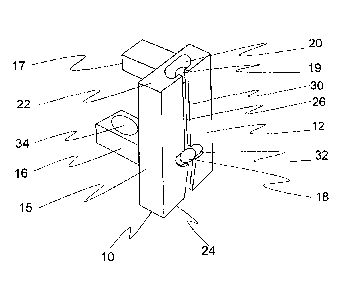
Variants, examples and preferred embodiments of the invention are described
hereinbelow. The
end piece for an edge rail is one-piece component fabricated from a plastic
material and provided
with an end plate 10. The end plate has a first end surface 12, a second end
surface 14, a first
side surface 13 and a second side surface 15, as well as a first edge surface
22 and a second
edge surface 24. The distance between side surfaces defines a width for the
end piece and the
end plate, and the distance between edge surfaces defines a height for the end
piece and the
end plate. The second end surface 14 is provided with two gripping
protrusions, a first gripping
protrusion 16 and a second gripping protrusion 17. The end piece is intended
to be mounted on
an end of the sunshade's edge rail in such a way that the second end surface
places itself against
an end surface of the edge rail. The edge rails of a sunshade are typically
hollow aluminum
profiles inside which there are lengthwise cavities or channels of the edge
rail. The gripping
protrusions are dimensioned and the position thereof on the second end surface
is determined
so as to fit inside the edge rail's cavities or channel tightly or with a
small clearance as the piece
is mounted to its position on the end of an edge rail. The side surfaces and
edge surfaces of an
end plate define a cross-sectional shape of the end plate. The shapes of side
surfaces and edge
CA 3035030 2019-02-26
6
surfaces are selected in such a way that the cross-sectional shape of an end
plate is substantially
identical to that of the sunshade's edge rail on whose end the end piece is to
be mounted. The
requirements imposed on the cross-sectional shape of an end piece's end plate
and on the shape
and location of gripping protrusions indicate that it is appropriate to
manufacture for different edge
rails an individual end piece compatible with a profile shape of the edge
rail.
Inside the end piece's end plate 10 is a string channel 20, having its first
end opening onto the
edge surface 22 and its second end opening onto the edge surface 24. The width
of the string
channel's cross-section exceeds the depth of its cross-section. In this
context, the string channel's
width refers to a dimension in the lateral direction of the end plate and the
depth refers to a
dimension in the direction perpendicular to the first end surface. Between the
string channel 20
and the first end surface 12 is a wall 30 provided with a through-going groove
26. The groove
extends across the entire height of the end plate, in other words, its first
end is at a first end of
the string channel and its second end is at a second end of the string
channel. The groove has a
width which is substantially smaller than that of the string channel. The
groove is intended to
enable placement of the guiding strings and support strings in the string
channel through the wall.
Therefore, the groove's width is dimensioned to be substantially equal to the
diameter of guiding
and support strings typically employed in sunshades.
Within a section between the first and second ends of the groove, the wall 30
has an aperture 32
at which the groove's width locally increases many times over and, in
alignment with the aperture,
the end plate has a first hole 18. The first hole extends through the end
plate and has its first end
opening into the string channel 20. A first section of the groove 26 extends
in a substantially linear
manner from the groove's first end to the aperture and so does a second
section of the groove
likewise in a substantially linear manner from the aperture to the groove's
second end. However,
the first and second sections are not co-directional as there is a bend in the
traveling direction at
the aperture 32. It is by virtue of the bend that the guiding string,
presently taut and straight in the
string channel, is not able to escape through the groove out of the string
channel.
The first gripping protrusion 16 included in the second surface 14 of the end
plate 10 has a wider
base portion and a narrower tip portion. A second end of the first hole 18
opens onto a surface of
the base portion in such a way that a bottom edge of the hole mouth settles
substantially flush
with a top surface of the tip portion. The first hole has its centerline
extending in a direction which
is substantially the same as the lengthwise direction of the tip portion. The
tip portion is provided
with an oval-shaped string opening 34, whose centerline direction is
perpendicular to the
centerline direction of the first hole and substantially co-directional with
the end piece's vertical
direction. The first hole and the string opening are constructed in the end
pieces for the
CA 3035030 2019-02-26
7
penetration of guiding strings and support strings included in a sunshade. The
sizes for a first
hole and a string opening are selected in such a way that a single hole or
string opening is able
to accommodate the passage of at least two, preferably 2-4, most preferably 3-
5, guiding and/or
support strings.
The second gripping protrusion 17 included in the second surface 14 of the end
plate is located
in vertical direction above the first gripping protrusion. Through the second
gripping protrusion
extends a second hole 19, which is lengthwise of the gripping protrusion and
has its first end
opening into the string channel and its second end opening onto an end surface
of the second
gripping protrusion. The second hole enables strings included in a sunshade or
its operating
mechanism to be guided through the end piece into the interior of an edge
rail.
In fig. 2 is shown, by way of example, a portion of one sunshade according to
the invention in a
view from the front. An edge rail 100 included in the sunshade, and end pieces
present at the
edge rail's ends, are presented in the figure as cross-sectioned in a
longitudinal direction of the
edge rail.
The edge rail is an aluminum profile with a top side 106 and a bottom side
108. Inside the edge
profile are two cavities lengthwise of the edge rail, an upper cavity 104 and
a lower cavity 110.
The lower cavity has in its wall a wall-penetrating slit, which has a length
of the entire cavity and
which opens onto the bottom side of the edge rail. The edge rail's first end
112 is provided with a
first end piece and the edge rail's second end 114 is provided with a second
end piece. Both end
pieces are identical end pieces as depicted in figs. 1a and lb. The end pieces
are mounted on
the ends of an edge rail in such a way that the end piece has its first
gripping protrusion 16
positioned in the lower cavity 110, its second gripping protrusion 17
positioned in the upper cavity
104, and the end piece has its second end surface 14 placed against an end
surface of the edge
rail. The illustrated sunshade is a so-called pleated blind, wherein the part
protecting from solar
radiation is a folding protective screen 102 constructed from a rigid fabric.
The protective screen
is fastened by its first edge to the edge rail's bottom side 108. The
protective screen has its second
edge provided with a second edge rail, which is identical to the first edge
rail and fastened to the
protective fabric in a similar fashion (the second edge rail is not shown in
the figures).
Each edge rail of the sunshade includes two guiding strings; a first guiding
string 28a and a
second guiding string 28b. The guiding strings are fastened by the ends
thereof to the end or side
edges of an opening to be covered, not shown in the figures, in such a way
that the guiding strings
in an assembled sunshade are in a taut condition. The first guiding string
28a, commencing from
a first edge of the sunshade, extends along the string channel 20 of an end
piece present at a
CA 3035030 2019-02-26
8
first end 112 of the edge rail to the first hole 18, proceeds by way of the
hole into an interior of the
edge rail and makes a turn towards the protective screen 102 through a string
opening 34 included
in the end piece. The first guiding string departs from inside the edge rail
by way of a slit included
in the lower cavity's wall. After departing from the edge rail, the first
guiding string continues its
passage through holes in the pleats towards a second edge rail not shown in
the figures.
The second guiding string 28a, commencing from a first edge of the sunshade,
extends along the
string channel 20 of an end piece present at a first end 112 of the edge rail
to the first hole 18 and
through the hole into an interior of the edge rail. Inside the edge rail, the
second guiding string
proceeds to the proximity of a second end of the edge rail and makes a turn
towards the protective
screen 102 through a string opening 34 included the end piece present at a
second end 114. The
second guiding string departs from inside the edge rail by way of a slit
included in the lower
cavity's wall and continues its passage through holes in the pleats towards a
second edge rail not
shown in the figures. The two guiding strings 28a, 28b, included in a second
edge of the
sunshade, extend through the end pieces in a similar fashion. When passing
through the first hole
and the string opening, the traveling directions of guiding strings change by
about 90 degrees.
The illustrated sunshade is further provided with a support string 36 bracing
the protective screen.
The support string extends into an interior of the edge rail along the same
path as the guiding
strings, in other words, by way of a string channel and a first hole included
in the end piece. Inside
the edge rail, the support string makes a turn, within a section between the
end pieces, towards
the protective screen and proceeds through holes in the protective screen's
pleats towards a
second edge rail not shown in the figures. The sunshade according to the
invention can be
provided with more than one support string, for example with two or three
support strings. The
demand for and number of support strings are dependent on the width of a
protective screen. In
narrow protective screens, support strings are not needed at all. Should the
number of support
strings be more than one, it is appropriate to conduct the support strings
into the interior of an
edge rail by way of opposite ends of the edge rail. In the sunshade according
to the invention,
both the guiding strings and the support strings can be conducted through an
end piece into the
interior of an edge rail by way of one and the same first hole.
In the foregoing specification there have been described a few preferred
embodiments for an end
piece and a sunshade of the invention. The invention is not limited to the
above-described
solutions, but the inventive concept can be applied in various ways within the
scope defined by
the claims.
CA 3035030 2019-02-26