Note: Descriptions are shown in the official language in which they were submitted.
CA 03035093 2019-02-25
WO 2018/037114
PCT/EP2017/071433
1
MONITORING A TRANSFORMER COMPRISING A TAP CHANGER
FIELD OF INVENTION
The present invention relates to a monitoring device, method and
computer program product for monitoring a transformer comprising a tap
changer.
BACKGROUND
Transformers equipped with tap changers are frequently used in different
types of power transmission environments, such as at 10 kV and above. A
transformer that comprises a tap changer is able to change the turns ratio
between the windings to thereby change voltage levels. This ability is in
many systems used for controlling the delivery of power.
Transformers are generally reliable. The probability of them failing is low,
such as around 1%. However, of those 1% that fail, typically 20 - 40% are
due to failure in the tap changer.
The reason for this is that the tap changer is the only part of the
transformer that has mechanically moving elements. Therefore this part of
the transformer is more likely to cause a failure than the rest of the
transformer.
When monitoring a transformer it would therefore be of interest to
monitor a tap change operation when the turns ratio is changed. If such
monitoring is performed then it may be possible to predict when the tap
changer is about to wear out. Thereby maintenance may be more easily
planned, which is of advantage both with regard to reliability and
economy.
Tap changer monitoring is described in a number of documents.
CA 03035093 2019-02-25
WO 2018/037114
PCT/EP2017/071433
2
US 2012/0173180 does for instance disclose a method and apparatus for
evaluating health of a tab changer. The health is evaluated through
separating a second discharge signal from a first discharge signal using a
third discharge signal and determining the health through comparing the
second discharge signal and a first initial value. The third discharge signal
may be a second initial value or a fourth discharge signal. The first initial
value is a signal generated in the tab changer and the second initial value is
a signal generated in a main tank of the transformer, while the first and
.. fourth discharge signals are high frequency currents in a grounded line of
the tab changer. The document also mentions the use of an output voltage
detector detecting the output voltage of a secondary coil and used in the
control of the tab changer.
EP 2541 572 discloses a protection arrangement for a tap changer where
the current through the tap changer is detected and used to generate a
current indication signal. The duration of the current indication signals is
then compared with a threshold and a fault indication signal generated if it
is.
JPH 08-213257 is concerned with obtaining a measure of the health of a
tap change based on a current signal corresponding to the current through
the tap changer.
JP 2000-208340 is concerned with using a waveform obtained through
measuring power transmission properties on one side of a transformer.
However, a tap change is not easily detected in the waveforms that are
available for monitoring purposes. This is especially the case when the
transformer is used at high loads. Furthermore, it is often not enough to
merely detect a tap change in a waveform. It may be necessary to also
extract information indicative of the health of the tap changer from such
CA 03035093 2019-02-25
WO 2018/037114
PCT/EP2017/071433
3
waveforms. It can thereby be seen that it may be very hard to determine
the health of a transformer using the available waveforms.
It is therefore of interest to monitor a transformer equipped with a tap
changer in a way that information indicating the performance of the tap
changer can be extracted using the available waveforms and used for
condition monitoring purposes.
The present invention is directed towards such transformer monitoring.
SUMMARY OF THE INVENTION
The present invention is thus directed towards monitoring a transformer
with regard to tap changer operation.
This object is according to a first aspect of the present invention achieved
through a monitoring device for monitoring a transformer comprising a
tap changer, where the transformer has at least two magnetically coupled
windings arranged at a first and a second transformer side and the tap
changer comprises impedance elements and a switch configured to
gradually pass the impedance elements when changing between two tap
changer positions during a tap change operation. The monitoring device in
turn comprises:
a waveform analyzer operative to
obtain waveforms of measured power transmission properties recorded at
the first and second transformer sides, said measured power transmission
properties being currents and/or voltages,
process the recorded waveforms for obtaining at least one waveform
representing a tap change operation, and
extract information indicative of the health of the tap change from said at
least one waveform that represents the tap change operation,
4
wherein the extracted information comprises an operation duration time
covering at least a part of the tap change operation and/or an amplitude of
said at least one waveform representing the tap change operation.
This object is according to a second aspect achieved through a method for
monitoring a transformer comprising a tap changer. The transformer has
at least two magnetically coupled windings and the tap changer comprises
impedance elements and a switch configured to gradually pass the
impedance elements when changing between two tap changer positions
during a tap change operation. The method is performed in a protection
device and comprises:
obtaining waveforms of measured power transmission properties recorded
at the first and second transformer sides, said measured power
transmission properties being currents and/or voltages
processing the recorded waveforms for obtaining at least one waveform
representing a tap change operation, and
extracting information indicative of the health of the tap change from said
at least one waveform that represents the tap change operation,
wherein the extracted information comprises an operation duration time
of at least a part of the tap change operation, or an amplitude of said at
least one waveform representing the tap change operation, or both.
The object is according to a third aspect of the present invention achieved
through a computer program product for monitoring a transformer
comprising a tap changer. The transformer has at least two magnetically
coupled windings and the tap changer comprises impedance elements and
a switch configured to gradually pass the impedance elements when
changing between two tap changer positions during a tap change
operation. The computer program product comprises a data carrier with
computer program code configured to cause a waveform analyzer of a
monitoring device to
CA 3035093 2019-03-29
CA 03035093 2019-02-25
obtain waveforms of measured power transmission properties recorded at
the first and second transformer sides, said measured power transmission
properties being currents and/or voltages
process the recorded waveforms for obtaining at least one waveform
5 representing a tap change operation, and
extract information indicative of the health of the tap change from said at
least one waveform that represents the tap change operation,
wherein the extracted information comprises an operation duration time
covering at least a part of the tap change operation and/or an amplitude of
said at least one waveform representing the tap change operation.
According to another aspect of the present invention, there is provided a
computer program product for monitoring a transformer comprising a tap
changer, said transformer having at least two magnetically coupled
windings and the tap changer comprising impedance elements and a
switch configured to gradually pass the impedance elements when
changing between two tap changer positions during a tap change
operation, the computer program product comprising a computer readable
memory storing computer executable instructions thereon that are
configured to cause a waveform analyser of a monitoring device to:
obtain waveforms of measured power transmission properties
recorded at the first and second transformer sides, said measured power
transmission properties being currents and/or voltages;
process the recorded waveforms for obtaining at least one waveform
.. representing the tap change operation; and
extract information indicative of a health of the tap changer from
said at least one waveform that represents the tap change operation,
wherein the extracted information comprises an operation duration
time covering at least a part of the tap change operation and/or an
amplitude of said at least one waveform representing the tap change
operation.
CA 03035093 2019-02-25
5a
The present invention has a number of advantages. It provides an
improved monitoring of a transformer equipped with a tap changer, where
it is possible to evaluate the performance of the tap changer. Thereby a
more reliable maintenance planning can be made. This is also done
without the need for monitoring dedicated tap changer properties but only
using measurement quantities that are traditionally available for a
transformer. Thereby the improved monitoring is also obtained using a
minimum of additional hardware and avoiding introduction of additional
sensors and retrofitting of waveform recorders.
BRIEF DESCRIPTION OF THE DRAWINGS
The present invention will in the following be described with reference
being made to the accompanying drawings, where
fig. 1 schematically shows a transformer equipped with a tap changer,
fig. 2 schematically shows the tap changer and one winding of the
transformer in fig. 1,
fig. 3 schematically shows power loss in the transformer occurring during a
tap change operation,
fig. 4 schematically shows a waveform recorder together with a waveform
analyzer for monitoring the transformer,
CA 03035093 2019-02-25
WO 2018/037114
PCT/EP2017/071433
6
fig. 5 shows a block schematic of a power loss handling block in the
waveform analyzer,
fig. 6 shows a flow chart of method steps in a first embodiment of a
method of monitoring the transformer being performed by the power loss
.. handling block in the waveform analyzer,
fig. 7 shows a block schematic of a current difference handling block in the
waveform analyzer,
fig. 8 shows a flow chart of method steps in a second embodiment of the
method of monitoring the transformer being performed by the current
.. difference handling block in the waveform analyzer,
fig. 9 shows a block schematic of a frequency domain processing block in
the waveform analyzer,
fig. 10 shows a flow chart of method steps in a third embodiment of the
method of monitoring the transformer being performed by the frequency
domain processing block in the waveform analyzer, and
fig. ii schematically shows a computer program product in the form of a
data carrier comprising computer program code for implementing the
waveform analyzing unit,
DETAILED DESCRIPTION OF THE INVENTION
In the following, a detailed description of preferred embodiments of the
invention will be given.
.. Fig. 1 shows a transformer 10 having a first winding 12 and a second
winding 14 magnetically coupled to each other. These windings thus form
a pair, often denoted primary and secondary windings. The first winding
12 is furthermore connected to a tap changer 16. In the figure there are
also shown a number of power transmission properties of the transformer
that may be measured during operation. There is an input current In fed
into and input voltage Uin applied over the first winding 12. There is also
an output current lout delivered from and an output voltage Uout
provided by the second winding 14. The input current In and the input
CA 03035093 2019-02-25
WO 2018/037114
PCT/EP2017/071433
7
voltage Uin are measurement quantities that are measured at a first and a
second measurement terminal MT1 and MT2 of the first winding 12, where
the first measurement terminal MT1 is provided at a first end of the first
winding 12 and the second measurement terminal MT2 at a second end of
the first winding 12. The output current lout and the output voltage Uout
are measurement quantities measured at a third and a fourth
measurement terminal MT3 and MT4 of the second winding 14, where the
third measurement terminal MT3 is provided at a first end and the fourth
measurement terminal MT4 is provided at a second end of the second
winding 14. It can thus be seen that electric power enters and exits the
transformer at the measurement terminals. The above described example
assumes a power transfer through the transformer from the first to the
second winding. Thereby the first winding 12 forms an input side and the
second winding an output side of the transformer to. However, it should
be realized that power may be transferred in the opposite direction, in
which case the input current and input voltage would be measured at the
third and fourth measurement terminals MT3 and MT4, while the output
current and output voltage would be measured at the first and second
measurement terminals MTi, and MT2. Then the second winding 14 would
.. form the input side and the first winding 12 would form the output side.
The measurement quantities are therefore also power transmission
properties that are measured at the measurement terminals.
The transformer shown is schematically represented. It should be realized
that it may also comprise an iron core. It should also be realized that a
transformer in many cases is a three-phase transformer. This means that
there would be three pairs of windings. A transformer may also comprise
more than one secondary winding magnetically coupled to the same
primary winding. The tap changer may as an alternative also be connected
.. to the second winding.
Fig. 2 schematically shows the first winding 12 together with a tap changer
that comprises a regulating winding 19. The first winding has a first and a
CA 03035093 2019-02-25
WO 2018/037114
PCT/EP2017/071433
8
second end, with the first end connected to the first measurement terminal
MT1 and the second end connectable to the regulating winding 19. The
regulating winding 19 also has a first and a second end. The tap changer
furthermore comprises a diverter 20 and a selector 18 that selects a
number of turns of the regulating winding 19 that are to be connected to
the primary winding 12.
The selector 18 has a selector switch 24 that is used to reverse the
orientation of the regulating winding 19 and therefore has a first end
connected to the second end of the first winding 12 and a second end
moveable between two positions, a first position at the first end of the
regulating winding 19 and a second position at the second end of the
regulating winding 19. Each winding 12 and 19 comprises a number of
turns of electrical conductor. Furthermore, the regulating winding 19
comprises a number of tap points of which six 1 2, 3, 4, 5 and 6 are shown
as an example. The tap points are used for determining how many turns of
the regulating winding 19 that are to be connected to the first winding 12
by a first selector arm connected to a first diverter terminal DTI_ and a
second selector arm connected to a second diverter terminal DT2.
The diverter 20 in turn comprises a diverter switch 22 with a first end
connected to the second measurement terminal MT2 and a second end
that is connectable between four contact positions, where a first contact
position Pi leads to the first diverter terminal DTI via a first diverter arm,
a second contact position leads to the first diverter terminal DTi via an
impedance element in the form of a first resistor Ri, a third contact
position leads to the second diverter terminal DT2 via an impedance
element in the form of a second resistor R2 and a fourth contact position
P4 leads directly to the second diverter terminal DT2 via a second diverter
arm. The diverter 20 is provided for commutating a load between the two
selector arms.
CA 03035093 2019-02-25
WO 2018/037114
PCT/EP2017/071433
9
It should here be realized that this is merely one realization of a selector
and diverter tap changer. There exist several other types of selector and
diverter tap changers. There also exist other types of tap changers. Another
type is for instance a selector-switch tap changer, which combines the
selection and commutation in one movement but have a similar contacting
sequence as the selector and diverter tap changer. Yet another example is a
vacuum tap changer, where the contact sequence often is modified but still
includes a time when power is lost in impedance elements. The shown tap
changer also comprises resistors as impedance element. However, it is also
known to use other types of impedance elements, such as inductors.
Furthermore in the shown tap changer there are two impedance elements.
It should be realized that it is also possible with fewer, such as one, or
even
more, such as three or four.
What is common for all these tap changers is that during a tap change
there is gradual movement of a switch between two positions, which in the
case of the tap changer in fig. 2 is the diverter switch 22 moving between
the first and fourth positions Pi and P4. When a tap change is desired one
of the selector arms is originally connected between a tap positon and the
corresponding diverter terminal. As an example the first selector arm may
be connected between the second tap position 2 shown in fig.2 and the first
diverter terminal DTi and at the same time the diverter switch 22 is in the
first contact position P1. Thereby the first selector arm is loaded, i.e. a
load
current thus passes through the first diverter arm and into the first
selector arm. A tap position that obtains a desired turns ratio change is
then selected for the non-loaded selector arm, which in this example is the
second selector arm. The second diverter terminal DT2 therefore connects
the unloaded second selector arm to the selected tap position, which in the
example of fig. 2 is the first tap position 1. In order to commutate the load,
i.e. to carry out the change of the turns ratio, the diverter switch 22 is
then
gradually moved from the first to the fourth contact position. In this
gradual movement the diverter switch 22 first establishes contact with the
first resistor Ri at the same time as there is contact with the first contact
CA 03035093 2019-02-25
WO 2018/037114
PCT/EP2017/071433
position Pi. Then the diverter switch 22 breaks the contact with the first
contact position Pi and the first diverter arm. The load current will now
only run through the first resistor Ri to the first selector arm. Thereafter
the diverter switch connects to the second resistor R2. At this point in time
5 the load current will run through both the resistors Ri and R2 to both
the
first and second selector arms. There will also be a circulating current that
is generated through the voltage difference between the diverter terminals
DTI. and DT2. This is followed by the diverter switch 22 breaking the
connection with the first resistor Ri and thereby load current is only
10 running through the second resistor R2 to the second selector arm.
Finally
the diverter switch will reach the fourth contact position P4 and then the
load current will run through the second diverter arm to the second
selector arm. Thereby the tap change operation is completed. It can be
seen that during such a movement energy is loaded or deposited into at
least one impedance element and in the example of fig. 2 in two resistors
Ri and R2, which energy is consumed in the case of a resistor but only
temporarily stored in the case of an inductor.
Through the above-mentioned operation of the tap changer in fig. 2, i.e.
during the gradual change between the positions Pi and P4, the
impedances Ri and R2 will be connected between the measurement
terminals MT3 and MT4 and therefore energy will be deposited in them. In
the present example real power is lost, since the impedances are resistors.
If the impedances were inductive then reactive power would instead be
stored.
The instantaneous power loss may for instance be determined according to
equation (i) below
3 Pioõ (t) = ptn (0_ pont (0 = E (vtn (t)I'7'
(t) _vOUt (wont (0) (1)
phases
CA 03035093 2019-02-25
WO 2018/037114
PCT/EP2017/071433
11
The equation, which is provided for a three-phase system, thereby defines
the power loss of a three-phase transformer. The instantaneous power loss
Ploss is thus calculated based on the power transmission property
measurements obtained at the first, second, third and fourth measurement
terminals MT', MT2, MT3 and MT4 as the input voltage Uin times the
input current In minus the output voltage Uout times the output current
Tout, where three such differences are obtained, one for each phase.
It is possible to obtain the real power loss from equation (1.) as an average
of the instantaneous power loss in a period and the reactive power loss as
an oscillation with an average of zero.
The way power loss appears at a low load of such a three-phase
transformer equipped with tap changer can be seen in fig. 3. In the figure
there is shown the power loss for each phase through a concerted tap
change operation in all three phases. There is a power Ploss _A in a first
phase, a power loss Ploss _B in a second phase and a power loss Ploss _C in
a third phase. These three power losses are furthermore summed up to a
total power loss Ploss, and the total power loss Ploss has the shape of a
"pulse". In the figure it can be seen that the tap changing operation is
carried out between times 0.00 and 0.02 S. It can be seen that the "pulse"
or this interval as an example has a width of 20 ms and the width is a peak
duration time of an energy deposition or a peak duration energy
deposition time and in this interval, each phase experiences power loss.
This peak duration time is an operation duration time ODT between a
rising edge and a falling edge of the "pulse". This time is termed an
operation duration time because the time duration corresponds to the
duration of at least some steps in the operation of the tap changer. It thus
covers at least a part of the tap change operation. It can more particularly
be seen that the operation duration time ODT more or less corresponds to
the time that the diverter switch 22 is solely connected to the resistors RI.
and R2. It can also be seen that the power loss during the tap changer
operation has an amplitude AMP. The amplitude and operation duration
CA 03035093 2019-02-25
WO 2018/037114
PCT/EP2017/071433
12
time ODT are examples of information that is indicative of tap changer
performance or tap changer health, is obtainable via recorded waveforms
and can be used for monitoring purposes.
Transformers are generally reliable. The probability of them failing is low,
such as around 1%. However, of that IA that fail, typically 20 - 40% are
due to failure in the tap changer.
As mentioned above the only moving elements of a transformer are
included in the tap changer. It can thereby be seen that the tap changer is
relevant to the reliability.
If the transformer is monitored with regard to the operation of the tap
changer, for instance through analyzing the changes of the operation
duration time and amplitude in tap change "pulses" over time, it is
possible to determine the health of the tap changer and thereby also the
health of the transformer. This can be used to better plan maintenance of
the transformer. A too short commutation time may be risky due to the
fact that possible arcs are most reliably quenched at current zero crossings.
This means that the operation duration time should be longer than half a
period. If the arc is able to survive the operation there will be a short
circuiting of the regulating windings, which will in turn develop a lot of
energy and cause the transformer to break down. A too short operation
duration time may thus correspond to a failed tap changer. On the other
hand, too long commutation times indicate that there is friction in the
system but no indication of breakdown. A long operation duration time is
thus an indication that service is needed. Through monitoring the changes
in the operation duration time it is thereby possible to predict when a
failure would occur as well as to plan service of the transformer. The
amplitude AMP in turn indicates the size of the resistance. If the amplitude
changes then the resistance changes. Furthermore a high amplitude
corresponds to a small resistance and a low amplitude to a high resistance.
The amplitude may be of importance if no "pulse" can be seen at all, which
CA 03035093 2019-02-25
WO 2018/037114
PCT/EP2017/071433
13
would mean that either the tap changer has not moved or that the
resistance is close to infinity, i.e. that the resistor is broken. Both these
situations are important fault cases, where the latter may give rise to arcs
that short-circuit the regulating winding.
However, there is a problem in that it is not possible to directly monitor
the tap changer. Transformers do not normally have any measurement
quantities that are directly related to the tap changing operation. The
monitoring of the health of the transformer with regard to the tap changer
would therefore have to be made using general transformer measurement
quantities, such as input/output currents and voltages.
Moreover, these general measurement quantities are not always that easy
to use. As can be seen in fig. 3 it is possible to obtain information that can
be used for tap changer monitoring purposes, for instance based on power
loss. However, as mentioned earlier fig. 3 shows the power loss at low
loads. If the transformer experiences a high load, then it is not that easy to
extract the information indicative of tap changer performance from the
available measured waveforms as fig. 3 would seem to suggest. The
information indicative of tap changer performance may then be "drowned"
in the steady-state data because of the reactive loss in the winding due the
inductance, which loss is proportional to the load current.
It can therefore be seen that there is a need to process available general
transformer waveforms in order to obtain information indicative of the
performance of a tap change operation, which information may be studied
in order to, for instance, plan maintenance.
The invention addresses this problem.
One way of addressing this problem is through the use of a monitoring
device.
CA 03035093 2019-02-25
WO 2018/037114
PCT/EP2017/071433
14
One way of realizing a monitoring device 25 is shown in. fig. 4. The
monitoring device 25 comprises a waveform recorder 26, which comprises
a waveform recording block WFR 28 that receives measurement quantities
of the transformer in the form of the measured power transmission
properties In, Uin, lout and out as well as a tap changer control signal
TC CTRL, which is a control signal sent to the tap changer in order to
effectuate or start a tap change operation. Such a control signal is typically
sent from a tap changer control unit, which as an example may be
associated with power control of a power transmission system. The
waveform recorder 26 also comprises a waveform memory WFM 30 in
which recorded waveforms are stored. When the tap changer control signal
TC CTRL is obtained by the waveform recorder 26, the waveform
recording block 28 records a number of waveforms of the input and output
currents and input and output voltages (if available) and stores these in
the waveform memory 30. The obtaining or reception of the tap changer
control signal TC CTRL thus triggers the recording of waveforms, which
recording then continues for a pre-determined time, such as for 10
seconds. This has the advantage of providing waveforms that clearly
coincide with a tap changer operation. Furthermore, the length is such that
it safely allows waveform prediction to be made. Also the control signal
typically precedes the actual tap change operation such that a reliable
prediction of a steady state operational waveform may be made.
The monitoring device 25 also comprises a waveform analyzer 34, which
comprises a power loss handling block PLH 36, a current difference
handling block CDH 38 and a frequency domain processing block FDP 40.
Each of these blocks provide a separate way of obtaining at least one
waveform from which it is possible to extract information indicative of a
tap change. Finally the waveform analyzer 34 comprises an information
analyzing block IA 43 and a health data memory HDM 42 in which (time
stamped) waveforms and/or (time stamped) tap changer performance
indication information are stored for condition monitoring purposes.
CA 03035093 2019-02-25
WO 2018/037114
PCT/EP2017/071433
The waveform analyser 34 may be implemented through a computer or a
processor with associated program memory comprising computer
instructions implementing the above described blocks. It may also be
realized through one or more dedicated components such as Application
5 Specific Integrated Circuits (ASICSs) or Field Programmable Gate Arrays
(FPGAs) realizing the blocks. It should also be realized that the waveform
analyzer sometimes only needs to comprise one of the power loss handling
block 36, current difference handling block 38 and frequency domain
processing block 40. It should also be realized that it is possible that the
10 information analyzing block 43 is omitted and its functionality provided
in
another entity such as a separate monitoring computer.
The realization of a waveform recorder 26 is as such known, but may in
some respects also be realized in the same way as the waveform analyser
15 34. It may however also comprise Analog/Digital (A/D) converters and
possibly also scaling units for scaling at least some of the received signals.
One way of operating the waveform analyser 26 in order to monitor the
transformer to will now be described with reference also being made to fig.
5, which shows a block schematic of the power loss handling block 36 and
to fig. 6, which shows a flow chart of a number of method steps in a
method of monitoring the transformer to performed in the power loss
handling block 36.
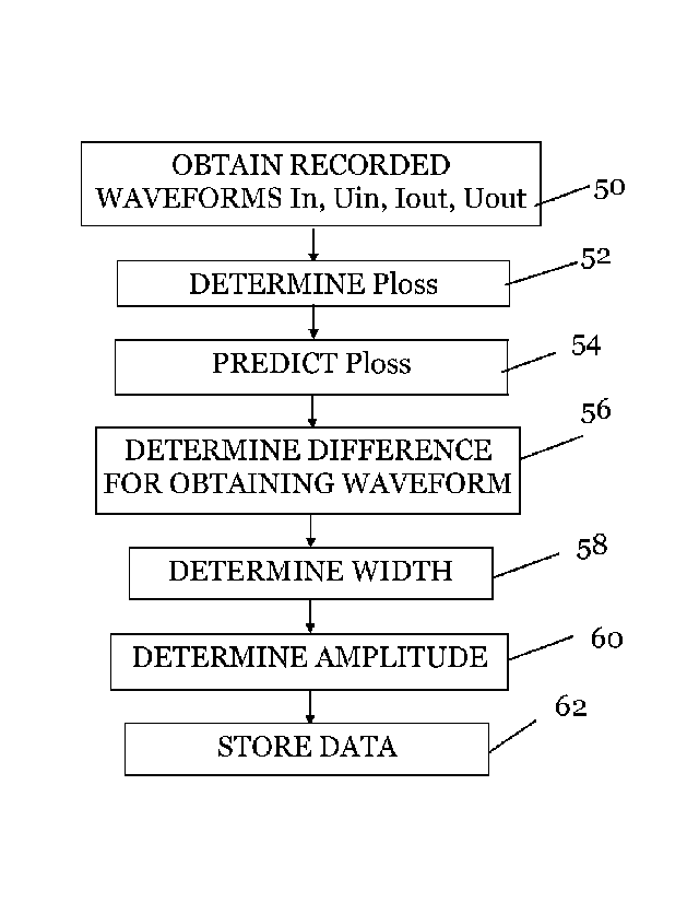
The power loss handling block 36 comprises a power loss determining
element PLD 44, a power loss predicting element PLP 46, a power loss
waveforming element PLWF 48 and a waveform analyzing element WFA
49-
As was mentioned above, the waveform recorder 26 records the waveforms
that appear at the measurement terminals when there is a tap change
operation triggered by the tap changer control signal TC CTRL, which
waveforms are stored in the waveform memory 30.
CA 03035093 2019-02-25
WO 2018/037114
PCT/EP2017/071433
16
The recorded waveforms also have a start point and an end point.
In order to obtain a waveform that is indicative of the performance of a tap
change, the power loss determining 44 element of the power loss handling
block 36 first obtains the recorded waveforms In, Uin, Ipout and Uout
from the waveform memory 30 of the waveform recorder 26, step 50,
which are thus the waveforms of power transmission properties recorded
at the first and second transformer sides.
Thereafter the power loss handling block processes the recorded
waveforms for obtaining at least one waveform representing a tap change
operation.
The processing of this first embodiment involves the processing of a
difference between a power transmission property on both sides of the
transformer using the measured power transmission properties. In this
first embodiment the power transmission property in question is the
derived property of power and the difference between the two sides is the
power loss through the transformer expressed as a power loss waveform.
The processing of this first embodiment furthermore involves predicting at
least one waveform of the same type as the difference waveform and
obtaining each waveform representing the tap change operation as a
difference between the difference waveform and the corresponding
predicted waveform, where there is one predicted waveform and one
difference waveform in this first embodiment.
Therefore the determining element 44 determines the power loss of the
transformer using the input and output current In, Uin, Tout and ()out
waveforms, step 52. The power loss may in this case be determined in the
way shown in equation (1) above.
17
At the same time, the power loss predicting element 46 predicts the same
power loss, step 54.
This prediction may comprise a prediction of the stationary waveforms of
current and voltage on the first and second sides of the transformer
Each such signal Uin, In, Uout, lout may be predicted from earlier
observations through generating a spectrum from an oscillating signal and
extracting the important frequency amplitudes. From these amplitudes the
waveform at future times can be predicted. The prediction method is
described in more detail in US 8095326.
The predicted waveforms may therefore correspond to stationary
waveforms of the currents and voltages at the first and second sides of the
transformer, i.e. waveforms without any embedded tap change
information. These predicted waveforms may then be used in the forming
of a predicted power loss, step 54.
Thereafter the powerloss waveforming element 48 determines the
difference between the determined and predicted power loss for obtaining
a waveform defining the tap change operation, step 56. The difference is
then used as a waveform that defines the tap change operation. As
mentioned above the prediction of power loss would represent the steady
state power loss without the tap change operation. Therefore, in such a
difference waveform essentially only the previously shown "pulse" of fig.3
should be present and thereby the information indicative of tap change
performance can be easily extracted from the waveform.
The difference may as an example be obtained as
AP/. (t) = Pross(t)¨ Prosimd (t) (2)
One way in which this may be done is through
CA 3035093 2019-03-29
CA 03035093 2019-02-25
WO 2018/037114
PCT/EP2017/071433
18
APioss Lphases1(t)A/1(t)+ AV, (t)/, (t) + AV, (t)A/, (t) .. (3)
Equation (3) shows a determination of an input or output power change,
where i thus encodes input or output side and AI and AV are the
differences between predicted and actual current and voltage waveforms.
The power loss difference between actual and predicted power loss will
then be:
AF:oss (t) APoi(t) AP oat(t) (4)
Thereby the steady state components have been removed and the result is
a waveform that represents the tap change operation and that in essence
only comprises the power loss due to the tap change operation. In this
waveform it is then easy to determine the width or operation duration time
ODT, for instance through identifying the time between the rising edge
and the falling edge in the waveform, step 58, as well as the amplitude
AMP, step 60, which determinations may be performed by the waveform
.. analyzing element 49. The information indicative of the performance of
the tap change operation, i.e. the amplitude AMP and operation duration
time ODT, may then be stored, possibly time stamped, together with the
power loss difference waveform, in the health data memory 42 for use in
condition monitoring of the transformer, step 62. In this regard also other
.. information may be stored, such as initial and final tap positions, load
currents etc.
Health determination and predictions may then be performed by the
information analyzing block 43. The information analyzing block 43 may
.. thus analyze the information ODT and AMP indicative of tap change
operation that is stored in the memory 42 by the waveform analyzing
element 49, estimate the wear of the transformer and determine when
maintenance is to be made or rather determine at which service window
the transformer is to be replaced or serviced. As an alternative it is
possible
.. that the power loss analyzing element 49 is omitted and the power loss
CA 03035093 2019-02-25
WO 2018/037114
PCT/EP2017/071433
19
waveforming element 48 stores the power loss difference waveform in the
health data memory 42. In this case the information analyzing block 43
may instead obtain the power loss difference waveform from the health
data memory 42 and extract the information ODT and AMP indicative of
tap change operation therefrom when determining the health of the
transformer.
It can in this way be seen that it is possible to identify a tap change
operation as well as to extract tap change performance indication
information using the available waveforms irrespective of the size of the
load. Thereby the planning of maintenance may be improved.
In short, it can be seen that an improved monitoring of a transformer
equipped with a tap changer is obtained, where it is possible to evaluate
the performance of the tap changer. Thereby a more reliable maintenance
planning can be made. This is also done without the need for dedicated tap
changer monitoring sensors but only using measurement quantities that
are traditionally available for a transformer. In this way the improved
monitoring is obtained using a minimum of additional hardware and also
without introduction of additional sensors and retrofitting of waveform
recorders.
It is known that in some substations all voltages are not accessible as some
voltages may be measured at a distant substation on the same line. In such
a case there are no voltage waveforms available and therefore the power
loss is impossible to use for obtaining waveforms from which tap change
indication information can be extracted.
A second embodiment where prediction is also used addresses this
situation.
This second embodiment will now be described with reference also being
made to fig. 7 and 8, where fig. 7 shows a block schematic of the current
CA 03035093 2019-02-25
WO 2018/037114
PCT/EP2017/071433
difference handling block 38 and fig. 8 shows a flow chart of a number of
method steps in the method of monitoring the transformer and being
performed by the current difference handling block 38.
5 The current difference handling block 38 comprises a current difference
determining element CDD 64, a current difference predicting element CDP
66, a current deviation waveform determining element CDWF 68 and a
current difference analyzing element 69.
10 Also in this embodiment there is processing of a difference between a
power transmission property on both sides of the transformer using the
measured power transmission properties. In this second embodiment the
power transmission property in question is the measured power
transmission property of current and the difference between the two sides
15 is the current difference between the two sides. Also in this case, the
processing involves predicting waveforms of the same type as the
difference waveform, i.e. predicting current difference waveforms. The
processing also comprises obtaining each waveform representing the tap
change operation as a difference between the difference waveform and the
20 corresponding predicted waveform. In this second embodiment two
waveforms are predicted, one forward in time and one backwards in time
from the difference waveform and the obtaining of at least one waveform
comprises obtaining two deviation waveforms; one as a difference between
the difference waveform and a first of the predicted waveforms and
another as a difference between the difference waveform and a second of
the predicted waveforms.
In order to obtain the at least one waveform that is indicative of the
performance of the tap changer, the current difference determining
element 66 of the current difference handling block 38 first obtains the
recorded waveforms In and lout of all phases from the waveform memory
30 of the waveform recorder 26, step 70, where the waveforms of the
measured power transmission properties in this embodiment only
CA 03035093 2019-02-25
WO 2018/037114
PCT/EP2017/071433
21
comprises current waveforms recorded at the first and second transformer
sides.
Thereafter the current difference determining element 64 determines a
.. current difference Idiff between the currents on the two sides of the
transformer, step 72.
The current difference may be based on the determining of partial current
differences for the different phases.
For a phase p, the corresponding partial current difference may be
obtained as
/out (0
(t) = (t P __ 1 (5)
np
where 12 is an effective ratio of the specific phase that is obtained using a
.. Discrete Fourier Transformation (DFT) calculation of the current
amplitudes and depends on the turns ratio and a current sensor calibration
error.
The total current difference for all phases may thereafter be determined as:
2 0 I,ct(t) (0)2 (I2diff (0)2 +
(I3diff (0)2 (6)
It is possible to make predictions of the current differences using the same
above-described prediction technique described above.
Therefore, in this embodiment the current difference predicting element
66 predicts a first difference current. The prediction may be made based
on the same equations (5) and (6) above that have been modified in line
with equations (2) and (3). Furthermore the prediction is in this case made
CA 03035093 2019-02-25
WO 2018/037114
PCT/EP2017/071433
22
in the forward direction starting from the beginning of the waveform and
towards the end of the recording, step 74.
The current deviation waveform determining element 68 then obtains or
determines a first current deviation waveform as the difference between
the actual and first predicted current difference waveforms, step 76. In this
waveform it is then possible for the current difference analyzing element
69 to detect the start of the tap change operation, step 78, for instance
through detecting a rising edge or high positive time derivative of the
waveform. It is also possible for it to detect an amplitude.
However, the end of the tap change operation is not as easy to detect using
the first current deviation waveform because the stationary waveforms
have been changed. Therefore, in order to detect the end of tap change
operation the current difference predicting element 66 predicts a second
current difference in the backward direction, i.e. starting at the end of the
waveform recording and going backwards in time, step 80.
This is followed by the current deviation waveform determining element
68 obtaining or determining a second current deviation waveform as the
difference between the actual and second predicted current difference
waveforms, step 82. In this waveform it is then possible for the current
difference analyzing element 69 to detect the end of the tap change
operation, step 84, for instance through detecting a falling edge or large
negative time derivative of the waveform. Also here it is possible to detect
an amplitude.
Through combining the two current deviation waveforms it is then
possible for the current difference analyzing element 69 to determine the
"pulse" width or operation time duration, step 86, and through looking at
any of the current deviation waveforms also the amplitude may be
determined or obtained, step 88. The information indicative of tap change
performance may then be stored, possibly time stamped, in the health data
CA 03035093 2019-02-25
WO 2018/037114
PCT/EP2017/071433
23
memory 42, step 90. Also here other information may be stored, such as
initial and final tap positions, load currents etc. It is also possible that
the
current deviation waveform determining element 66 stores the first and
second current deviation waveforms in the memory 42.
The information analyzing block 43 may thereafter analyze the stored
information and/or waveforms for condition monitoring purposes. Also
here it is possible that the information analyzing block 43 extracts the tap
change performance indication information from the current deviation
waveforms if this has not already been done.
The second embodiment is thus an alternative to the first embodiment
when there are no measured voltages available from the waveform
recorder 26.
Both the above described embodiments rely on concerted tap change
operation in the three phases. However, for some tap changer installations,
most notably when there are three separate tap changers, one for each
phase, the tap change operation of the different phases may not be
concerted. The tap change operation may thus be performed
independently of each other in the different phases. Therefore it may be
necessary to monitor the transformer with regard to a tap change
operation separately for the three phases.
The above described power loss and current difference approaches are
hard to use for this scenario.
A third embodiment that is directed towards extracting information
indicative of tap change performance individually for the different phases
will now be described with reference being made to fig. 9 and 10, where fig.
9 shows a block schematic of the frequency domain processing block 40
and fig. 10 shows a flow chart of a number of method steps in the method
CA 03035093 2019-02-25
WO 2018/037114
PCT/EP2017/071433
24
of monitoring the transformer being performed by the frequency domain
processing block 40.
The frequency domain processing block 40 comprises a DFI' processing
element MI 92, a difference signal forming element DSF 94 and a
difference signal handling element DSH 96.
The DFT processing element 92 of the frequency domain processing block
obtains the recorded waveforms In an lout of all phases from the
waveform memory 30 of the waveform recorder 26, step 98.
Also in this embodiment there is processing of a difference between a
power transmission property on both sides of the transformer based on the
measured power transmission properties. Also in this third embodiment
the power transmission property is the current and the difference between
the two sides is the current difference between the two sides. However,
unlike in the previous embodiments there is in this case a determining of a
time dependent Discrete Fourier Transformation (DFT) phasor on the first
and second transformer side and the forming of a time dependent
difference phasor as a difference between these two DFT phasors.
Therefore the information is extracted from the time dependent difference
phasor.
The operation of the third embodiment is more particularly the following:
It then extracts DFT phasors using the DFT transforming unit, step 100.
A DFT phasor may be obtained as a complex time varying DFT amplitude
in a frequency analysis that is made for the operational frequency of the
current, which may be 50 Hz.
A DFT phasor may as an example be obtained as:
CA 03035093 2019-02-25
WO 2018/037114 PCT/EP2017/071433
N
I DFT (c) I2 e2x*j i(t 4) (7)
N
where N = ts/T with 'L., being the sampling time interval, T the fundamental
period, tk the sampling time instances and I(ti,k) the current at a time
5 instance ti k for a calculation around tk.
The above mentioned calculation may then be repeated over the entire
waveform and increasing k with at least one between each calculation.
10 Thereafter the difference signal forming element 94 forms one difference
signal or current difference phasor per phase and this is done through
obtaining a difference between the two current phasors of a phase, step
102.
15 The difference may more particularly be obtained as
I i1;1
fit!
Oh I
an (8)
12
where /"T is again a ____ phasor and n a ratio.
A current difference phasor may be complemented through using a value
of n that is the average of the complex DFT ratio estimates before and after
tap change operation.
The current difference phasors may provide a waveform for a phase having
a width and amplitude that can be detected.
The phasor difference signal is then provided to the difference signal
handling element 96, which determines the operation time duration, step
104, and amplitude, step 106, for each phase and stores them, possibly
time stamped, in the health data memory 42 for use in condition
CA 03035093 2019-02-25
WO 2018/037114
PCT/EP2017/071433
26
monitoring of the transformer, step 1o8. It is also possible that the
difference signal forming element 94 stores the difference signals in this
memory 42. Also in this case other information may be stored, such as
initial and final tap positions, load currents etc.
The difference signals are thus signals from which information indicative
of tap changer performance may be extracted, such as operation time
duration and amplitude. Thereby an amplitude and an operation time
duration may be obtained for each phase. This is thus done for each phase
and therefore it is possible to determine health also for a tap changer
where tap change operation in respect of the different phases is more or
less independent from each other.
Thereby it is possible to obtain individual measures of the health of the tap
changer per phase which may also be used in condition monitoring. This
may be used together with any of the previously mentioned monitoring
methods used in the first or second embodiments.
There are a number of variations that may be made apart from those
already described. It is for instance possible that the monitoring device
only comprises the waveform analyzer that is set to communicate with the
waveform recorder. It is also possible that the monitoring device is
provided as a part of an Intelligent Electronic Device (TED) provided for
the transformer.
The waveform analyzer may be realized in the form of discrete
components. However, it may also be implemented in the form of a
processor with accompanying program memory comprising computer
program code that performs the desired control functionality when being
run on the processor. A computer program product carrying this code can
be provided as a data carrier such as one or more CD ROM discs or one or
more memory sticks carrying the computer program code, which performs
the above-described waveform analyzer functionality when being loaded
CA 03035093 2019-02-25
WO 2018/037114
PCT/EP2017/071433
27
into a waveform analyzer. One such data carrier in the form of a CD Rom
disk no carrying computer program code 102 is shown in fig.
From the foregoing discussion it is evident that the present invention can
be varied in a multitude of ways. It shall consequently be realized that the
present invention is only to be limited by the following claims.