Note: Descriptions are shown in the official language in which they were submitted.
WING FLAP WITH TORQUE MEMBER AND METHOD FOR FORMING THEREOF
FIELD
[0001] The present disclosure is generally related to aircraft and, more
particularly, to an aircraft wing flap having a torque member that is
integrally formed
with at least a portion of a flap body and a method for forming the wing flap.
BACKGROUND
[0002] Fixed-wing aircraft typically include various flight control surfaces
that enable adjustment and control of the aircraft's flight. For example,
flaps
mounted on trailing edges of wings modify the effective contour of the wings
and,
thus, modify the lift characteristics of the wings. In certain types of flap
systems, an
inboard flap includes a torque member that is used to move the flap between
stowed
and deployed positions. Typically, the torque member extends into the side of
the
fuselage, or into a wing fairing structure of the fuselage, and is coupled to
a flap
support mechanism that controls movement of the flap.
[0003] In many flap systems, the torque member is a tubular structure
having a circular cross-sectional shape, commonly referred to as a torque
tube. The
torque tube is typically coupled to a structural member of the flap, such as
an
inboard rib.
However, achieving appropriate structural and load-bearing
performance can require a heavy torque tube and large and complex couplings
that
increase the weight and cost of the aircraft. Additionally, some flap systems
utilize a
failsafe torque tube that includes a dual torque tube design that further
increases the
cost, weight, and complexity of the aircraft.
[0004] Accordingly, those skilled in the art continue with research and
development efforts in the field of aircraft wing flap actuation.
- 1 -
Date Recue/Date Received 2022-09-16
SUMMARY
[0005] In an example, the disclosed wing flap includes a flap body and a
torque member being integrally formed with at least a portion of the flap
body.
[0006] In an example, the disclosed wing of an aircraft includes a wing body
and a wing flap. The wing flap includes a flap body movably coupled to the
wing
body and a torque member being integrally formed with at least a portion of
the flap
body.
[0007] In an example, the disclosed method includes a step of integrally
forming a torque member with at least a portion of a flap body to form a wing
flap.
The flap body is configured to be movably coupled with a wing of an aircraft.
The
torque member is configured to be coupled to a flap actuator of the aircraft.
[0008] In one embodiment, there is provided a wing flap for an aircraft wing.
The wing flap comprises a flap body, a torque member integrally formed with at
least
a portion of the flap body, an upper skin, a lower skin, opposite the upper
skin and a
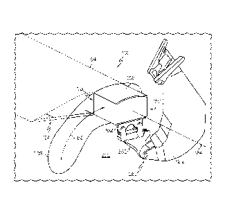
plurality of spars that extend between the upper skin and the lower skin. The
torque
member is integrally formed with at least one of the plurality of spars. At
least one of
the plurality of spars comprises a spar major portion and a spar extension
portion
that extends from the spar major portion. The flap body is partially formed by
the
spar major portion. The torque member is partially formed by the spar
extension
portion. The flap body comprises an inboard end, an outboard end, which is
opposite the inboard end, and comprises a leading end, and a trailing end,
which is
opposite the leading end. The torque member comprises an inboard end and an
outboard end opposite the inboard end and the torque member is integrated with
the
inboard end of the flap body and extends from the inboard end of the flap body
in an
inboard direction.
- 2 -
Date Recue/Date Received 2022-09-16
[0009] In another embodiment, there is provided an aircraft wing comprising
a wing body and the wing flap described above or variations thereof, wherein
the flap
body is movably coupled to the wing body and the torque member is couplable to
a
flap actuator of an aircraft.
[0010] In another embodiment, there is provided an aircraft comprising the
aircraft wing above, wherein the torque member is coupled to a flap actuator
of the
aircraft.
[0011] In another embodiment, there is provided a method for forming and
installing the wing flap above or variations thereof. The method comprises
integrally
forming the torque member with at least a portion of the flap body to form the
wing
flap, wherein the flap body is configured to be movably coupled with a wing of
an
aircraft and the torque member is configured to be coupled to a flap actuator
of the
aircraft.
[0012] In another embodiment, there is provided a wing flap comprising at
least three spars, wherein each one of at least the three spars comprises a
spar
major portion and a spar extension portion that extends from the spar major
portion.
The wing flap further comprises an upper skin, coupled to at least the three
spars
and comprising an upper-skin major portion and an upper-skin extension portion
that
extends from the upper-skin major portion. The wing flap further comprises a
lower
skin, coupled to at least the three spars, opposite the upper skin, and
comprising a
lower-skin major portion and a lower-skin extension portion that extends from
the
lower-skin major portion. The spar major portion of each one of at least the
three
spars, the upper-skin major portion, and the lower-skin major portion at least
partially
define a flap body of the wing flap. The spar extension portion of each one of
at
least the three spars, the upper-skin extension portion, and the lower-skin
extension
portion at least partially define a torque member of the wing flap. The spar
extension
portion of each one of at least the three spars is straight and is oblique to
the spar
extension portion of any another one of at least the three spars. The flap
body
comprises a leading edge, a trailing edge that is opposite the leading edge,
an
- 3 -
Date Recue/Date Received 2022-09-16
outboard end, an inboard end that is opposite the outboard end, and a flap-
body
width dimension between the leading edge and the trailing edge. The torque
member extends from the inboard end of the flap body and comprises a torque-
member width dimension that is less than the flap-body width dimension.
[0013] In another embodiment, there is provided a method for forming a
wing flap. The method involves at least partially forming a flap body of the
wing flap
with a spar major portion of each one of at least three spars, an upper-skin
major
portion of an upper skin, and a lower-skin major portion of a lower skin. The
method
further involves at least partially forming a torque member of the wing flap
with a
spar extension portion of each one of at least the three spars, extending from
the
spar major portion of each corresponding one of at least the three spars, an
upper
skin extension portion of the upper skin, extending from the upper-skin major
portion
of the upper skin, and a lower-skin extension portion of the lower skin,
extending
from the lower-skin major portion of the lower skin. The flap body comprises a
leading edge, a trailing edge that is opposite the leading edge, an outboard
end, an
inboard end that is opposite the outboard end, and a flap-body width dimension
between the leading edge and the trailing edge. The the torque member extends
from the inboard end of the flap body and comprises a torque member width
dimension that is less than the flap-body width dimension.
[0014] In another embodiment, there is provided a wing flap, comprising a
first spar comprising a first-spar major portion and a first-spar extension
portion that
extends from the first-spar major portion. The wing flap further comprises a
second
spar, comprising a second-spar major portion and a second-spar extension
portion
that extends from the second-spar major portion. The wing flap further
comprises a
third spar and an upper skin, coupled to the first spar, the second spar, and
the third
spar and comprising an upper-skin major portion and an upper-skin extension
portion that extends from the upper-skin major portion. The wing spar further
comprises a lower skin, coupled to the first spar, the second spar, and the
third spar,
opposite the upper skin, and comprising a lower-skin major portion and a lower-
skin
- 4 -
Date Recue/Date Received 2022-09-16
extension portion that extends from the lower-skin major portion. The first-
spar
major portion, the second-spar major portion, the third spar, the upper-skin
major
portion, and the lower-skin major at least partially define a flap body of the
wing flap.
The first-spar extension portion, the second-spar extension portion, the upper-
skin
extension portion, and the lower-skin extension portion at least partially
define a
torque member of the wing flap. The torque member comprises an extension rib,
coupled to the first-spar extension portion, the second-spar extension
portion, the
upper-skin extension portion, and the lower-skin extension portion. The flap
body
comprises a leading edge, a trailing edge that is opposite the leading edge,
an
outboard end, an inboard end that is opposite the outboard end, and a flap-
body
width dimension between the leading edge and the trailing edge. The torque
member extends from the inboard end of the flap body and comprises a torque-
member width dimension that is less than the flap-body width dimension.
[0015] Other examples of the disclosed wing flap and method will become
apparent from the following detailed description and accompanying drawings.
BRIEF DESCRIPTION OF THE DRAWINGS
[0016] Fig. 1 is a schematic, perspective view of an example of an aircraft;
[0017] Fig. 2 is a schematic, perspective view of an example of a wing of
the aircraft;
[0018] Fig. 3 is a schematic, perspective view of an example of a disclosed
wing flap;
[0019] Fig. 4 is a schematic, interior, perspective view of an example of a
portion of the aircraft showing an example of a torque member of the disclosed
wing
flap extending through an opening in a fuselage of the aircraft;
- 5 -
Date Recue/Date Received 2022-09-16
[0020] Fig. 5 is a schematic, partial, perspective view of an example of the
disclosed wing flap;
[0021] Fig. 6 is a schematic, elevation, cross-sectional view of an example
of a disclosed wing flap;
[0022] Fig. 7 is a schematic, partial, plan view of an example of the
disclosed wing flap;
[0023] Fig. 8 is a schematic, plan view of an example of the disclosed wing
flap;
[0024] Fig. 9 is a schematic, partial, plan view of an example of the
.. disclosed wing flap;
[0025] Fig. 10 is a schematic, partial, plan view of an example of the
disclosed wing flap;
[0026] Fig. 11 is a schematic, partial, plan view of an example of the
disclosed wing flap;
[0027] Fig. 12 is a schematic, partial, plan view of an example of the
disclosed wing flap;
[0028] Fig. 13 is a schematic, partial, plan view of an example of the
disclosed wing flap;
[0029] Fig. 14 is a schematic, partial, plan view of an example of the
disclosed wing flap;
[0030] Fig. 15 is a schematic, partial, plan view of an example of the
disclosed wing flap;
[0031] Fig. 16 is a schematic, partial, plan view of an example of the
disclosed wing flap;
- 6 -
Date Recue/Date Received 2022-09-16
[0032] Fig. 17 is a schematic, partial, plan view of an example of the
disclosed wing flap;
[0033] Fig. 18 is a schematic, partial, plan view of an example of the
disclosed wing flap;
[0034] Fig. 19 is a schematic, perspective view of an example of the
disclosed wing flap;
[0035] Fig. 20 is a flow diagram of an example of a disclosed method; and
[0036] Fig. 21 is a flow diagram of an example aircraft production and
service methodology.
DETAILED DESCRIPTION
[0037] The following detailed description refers to the accompanying
drawings, which illustrate specific examples described by the disclosure.
Other
examples having different structures and operations do not depart from the
scope of
the present disclosure. Like reference numerals may refer to the same feature,
element, or component in the different drawings.
[0038] Illustrative, non-exhaustive examples of the subject matter according
the present disclosure are provided below.
[0039] Fig. 1 is an illustrative example of an aircraft 200. In the
illustrative
example, the aircraft 200 is a fixed-wing aircraft. The aircraft 200 includes
a
fuselage 202, a pair of wings 214 (also referred to individually as wing 214),
and a
propulsion system 216. The aircraft 200 also includes a plurality of high-
level
systems, such as, but not limited to, an electrical system 226, a hydraulic
system
228, and/or an environmental system 230. Any number of other systems may also
be included.
- 7 -
Date Recue/Date Received 2022-09-16
[0040] The fuselage 202 is the main body of the aircraft 200 and includes
any suitable central structure configured to hold a crew, one or more
passengers,
and/or cargo. In the illustrative example, the fuselage 202 is an elongate,
generally
cylindrical fuselage. The fuselage 202 includes a nose portion at a forward
end of
the fuselage 202 and a tail portion at an aft end of the fuselage 202. As used
herein,
the terms "forward" and "aft" have their ordinary meaning as known to those
skilled
in the art and refer to positions relative to a direction of movement of the
aircraft 200.
The tail portion may also include a vertical stabilizer 240 and horizontal
stabilizers
238.
[0041] The fuselage 202 includes an airframe 222 that defines an interior
224, which may include a passenger compartment and/or a cargo compartment. A
wing fairing structure 220 (e.g., fuselage/wing fairing) may also be provided
at each
interface between the fuselage 202 and the wing 214 and may extend from
proximate (at or near) the fuselage 202 to proximate the wing 214 associated
.. therewith.
[0042] The wings 214 include any suitable airfoil structures that are
configured to provide lift to the aircraft 200. In the illustrative example,
the wings 214
are elongate structures extending from a lower portion of the fuselage 202 in
a swept
wing, tapered planform. In other examples, the wings 214 are straight or delta-
shaped. In still other examples, the wings 214 are trapezoidal, constant,
elliptical,
semi-elliptical, or other configurations known in the art.
[0043] In the illustrative example, the propulsion system 216 includes two
turbofan engines mounted to the wings 214, for example, by pylons. In an
example,
each engine is housed in a nacelle, which includes an inlet and a nozzle. In
other
examples, the engines may be mounted to the fuselage 202 or other aircraft
structures, such as the tail portion. In various other examples, the
propulsion system
216 may include more or fewer engines and other types of engines (e.g.,
turboprop
engines) may be used.
- 8 -
Date Recue/Date Received 2022-09-16
[0044] The aircraft 200 includes various flight control surfaces 232. The
flight control surfaces 232 include any pivoting aerodynamic device that is
used to
adjust and control flight and aerodynamic characteristics of the aircraft 200.
Examples of the flight control surfaces 232 include an inboard flap 208 and/or
an
outboard flap 218 that are located on the trailing end of the wings 214, an
elevator
234 that is located on the trailing end of the horizontal stabilizers 238, a
rudder 236
that is located on the trailing end of the vertical stabilizer 240, and other
control
surfaces, such as leading end flaps, ailerons, and spoilers. As used herein,
the
terms "inboard" and "outboard" have their ordinary meaning as known to those
skilled in the art and refer to positions relative to a center line of the
aircraft 200.
[0045] In an example, the inboard flap 208 (also referred to collectively as
inboard flaps 208) and/or the outboard flap 218 (also referred to collectively
as
outboard flaps 218) include any suitable structure mounted on the trailing
edge of
the wing 214 and configured to pivot, rotate, and/or translate (e.g., forward
and aft)
relative to the wing 214. The inboard flaps 208 and/or the outboard flaps 218
are
configured to alter the lift characteristics of the wing 214. The inboard
flaps 208
and/or the outboard flaps 218 are movable between at least a raised (stowed,
retracted, or "flaps up") position and a lowered (deployed, extended, or
"flaps down")
position. In an example, the inboard flaps 208 and/or the outboard flaps 218
are
pivotable about a fixed axis. In an example, the inboard flaps 208 and/or the
outboard flaps 218 pivot through a predetermined path, which is generally
arcuate of
curved.
[0046] In an example, the aircraft 200 also includes a flap actuator 260.
The flap actuator 260 is associated with each wing 214 for actuating the
inboard flap
208. In an example, the flap actuator 260 includes a motorized arm that is
located,
or housed, within the fuselage 202, or the wing fairing structure 220.
[0047] In an example, a torque member 210 couples the flap actuator 260
with the associated inboard flap 208 to transfer an actuating/de-actuating
(e.g.,
lowering/raising) force from the flap actuator 260 to the associated inboard
flap 208.
- 9 -
Date Recue/Date Received 2022-09-16
The torque member 210 extends through an opening 206 in the aircraft 200
(e.g., an
opening 206 in the fuselage 202 or the wing fairing structure 220). The
opening 206
in the aircraft 200 is sized and shaped to accommodate a travel path of the
torque
member 210 as the inboard flap 208 is lowered and raised.
[0048] Fig. 2 is an illustrative example of the wing 214. The wing 214 is any
one of various wing structures that includes a wing body 258. The wing body
258 is
formed of various structural members including, but not limited to, an upper
wing
skin 246, a lower wing skin 248, a plurality of wing spars 250 that extend
between
the upper wing skin 246 and the lower wing skin 248, and a plurality of wing
ribs 252
that extend between the upper wing skin 246 and the lower wing skin 248. These
structural members are coupled together by any one of various methods
including,
but not limited to, connection by various kinds of fasteners, co-curing, or
integrally
forming. The wing spars 250 extend in a span-wise direction between a wing
root
254 of the wing 214 and a wing tip 256 of the wing 214. The wing ribs 252
extend in
a chord-wise direction between a leading edge 244 of the wing 214 and a
trailing
edge 242 of the wing 214. The wing 214 further includes a wing flap 100. An
example of the disclosed wing flap 100 is movably coupled with the wing 214 at
the
trailing edge 242 of the wing 214 proximate to the wing root 254.
[0049] Referring to Figs. 3-19, disclosed are various examples of the wing
flap 100. The disclosed wing flap 100 includes a flap body 164 and a torque
member 108 that is integrally formed with at least a portion of the flap body
164.
The torque member 108 extends from the inboard end 124 of the flap body 164 in
an
inboard direction. As used herein, the phrase "integrally formed" refers to
parts (e.g.,
constituents or components) being of, pertaining to, or belonging as a part of
a
unitary whole, in which the parts are organically joined or linked during
formation to
form the unitary whole, and requires more than mere interconnected parts.
[0050] In an example, the torque member 108 is integrally formed with at
least one structural member 198 (Figs. 6 and 7) of the flap body 164. As used
herein, the phrase "structural member," with reference to any one of a
plurality of
- 10 -
Date Recue/Date Received 2022-09-16
structural members 198 that partially form the wing flap 100, refers to a load-
bearing
element that is configured to carry a load or react to stresses applied to the
wing flap
100. Generally, the structural members 198 that partially form the wing flap
100
include, but are not limited to, spars, ribs, stringers, and the like. For
example, the
flap body 164 and the torque member 108 share a common structural member 198,
such as a spar 106 that extends along the wing flap 100 in a span-wise
direction. In
an example, the flap body 164 includes outer skins (e.g., an upper skin 102
and a
lower skin 104) and a plurality of spars 106 and the torque member 108 is
integrally
formed by a portion of at least one of the plurality of spars 106 that extends
from the
flap body 164 in an inboard direction. Accordingly, and as discussed in more
detail
below, the wing flap 100 includes the upper skin 102 and the lower skin 104.
The
wing flap 100 further includes a plurality of spars 106 extending between the
upper
skin 102 and the lower skin 104.
[0051] The torque member 108 being integrally formed with at least a
portion of the flap body 164 may reduce the cost, complexity, and/or weight of
the
wing flap 100 by utilizing a portion of the existing structure of the flap
body 164 to
form at least a portion of the torque member 108. As an example, the torque
member 108 being integrally formed with at least a portion of the flap body
164 may
reduce the complexity and costs typically associated with coupling a torque
member,
such as a conventional torque tube, with an inboard flap of an aircraft wing.
For
example, forming the torque member 108 from a portion of an existing
structural
member 198 (e.g., a spar 106) of the wing flap 100 is less costly than
fabricating a
metal (e.g., titanium or steel) torque tube, reduces the components and time
as
compared to that required to assemble and join the metal torque tube to the
wing
flap, and reduces concentrated loading locations formed at joints.
[0052] As another example, the torque member 108 being integrally formed
with at least a portion of the flap body 164 may reduce the weight of the
aircraft wing
and reduce the costs associated with production of the aircraft wing and/or
the
aircraft. For example, forming the torque member 108 from a portion of an
existing
- 11 -
Date Recue/Date Received 2022-09-16
structural member 198 (e.g., a spar 106) of the wing flap 100 requires fewer
joints
than coupling the metal torque tube to the wing flap. As another example,
forming
the torque member 108 from a portion of an existing structural member 198 made
of
carbon fiber reduces a risk of corrosion and offers increases durability as
compared
to a metal torque tube. As yet another example, the torque member 108 being
integrally formed with at least a portion of the flap body 164 is stiffer than
the metal
torque tube that is coupled to the wing flap, which may reduce structural
deflection.
[0053] The wing flap 100 is an example of the inboard flap 208 of the wing
214 of the aircraft 200 and the torque member 108 is an example of the torque
member 210 of the inboard flap 208 (Fig. 1). In other examples, the teachings
of the
present disclosure may be applied to one or more other flight control surfaces
232 of
the aircraft 200.
[0054] In an example, the wing flap 100 includes any suitable pivoting
structure that is mounted on, or is otherwise movably coupled with, the wing
body
258 of the wing 214 at the trailing edge 242 of the wing 214 (Figs. 1 and 2).
In an
example, the wing flap 100 is located adjacent to the wing fairing structure
220 of the
fuselage 202 of the aircraft 200. During operation of the wing flap 100, the
wing flap
100 is movable between at least a raised (stowed, retracted, or "flaps up")
position
and a lowered (deployed, extended, or "flaps down") position to alter the lift
characteristics of the wing.
[0055] Referring to Fig. 3, the flap body 164 includes an inboard end 124
and an outboard end 126 opposite the inboard end 124. The flap body 164 also
includes a leading end 112 and a trailing end 116 opposite the leading end
112. The
torque member 108 includes an inboard end 180 and an outboard end 178 opposite
the inboard end 180. In an example, the torque member 108 is integrated with
the
inboard end 124 of the flap body 164 and extends outward from the inboard end
124
of the flap body 164 in an inboard direction.
- 12 -
Date Recue/Date Received 2022-09-16
[0056] In an example, the torque member 108 is located toward or
proximate to (e.g., at or near) the leading end 112 of the flap body 164. In
an
example, the torque member 108 is located toward or proximate to the trailing
end
116 of the flap body 164. In an example, the torque member 108 is located
between
the leading end 112 and the trailing end 116 of the flap body 164, such as
proximate
to a middle portion of the flap body 164.
[0057] In an example, the torque member 108 has a cross-sectional shape
that at least partially matches, or matches a portion of, a cross-sectional
shape of
the flap body 164 as viewed from the inboard end 124. The cross-sectional
shape of
the torque member 108 at least partially matching the cross-sectional shape of
the
flap body 164 at the inboard end 124 of the flap body 164 may reduce
complexity
associated with coupling the torque member 108 to the flap body 164 and may
reduce the impact the torque member 108 has on the aerodynamic characteristics
of
the wing flap 100 and/or the aircraft 200. As used herein, components having
at
least partially matching cross-sectional shapes may have, but do not require,
matching sizes and/or dimensions.
[0058] In an example, the torque member 108 has a non-circular cross-
sectional shape. As an example, the torque member 108 has a polygonal cross-
sectional shape. In the illustrative example, the torque member 108 has a
rectangular cross-sectional shape. In another illustrative example, the torque
member 108 has a cross-sectional shape including a combination of linear and
arcuate sides, such as three substantially linear sides and a fourth arcuate
side
connecting two linear sides to form a generally rectangular cross-sectional
shape.
[0059] In an example, the torque member 108 includes, or is at least
partially formed by, a front wall 156, a rear wall 158 that is opposite the
front wall
156, an upper wall 160, and a lower wall 162 that is opposite the upper wall
160. At
least one of the front wall 156, the rear wall 158, the upper wall 160, and
the lower
wall 162 is integrally formed with the flap body 164. In an example, at least
one of
- 13 -
Date Recue/Date Received 2022-09-16
the upper wall 160 and the lower wall 162 has a profile shape that matches a
portion
of the flap body 164 as viewed from the inboard end 124.
[0060] A profile shape of each one of the front wall 156, the rear wall 158,
the upper wall 160, and the lower wall 162, as viewed from the inboard end
124,
defines the cross sectional shape of the torque member 108. In an example, the
profile shape of one or more of the front wall 156, the rear wall 158, the
upper wall
160, and the lower wall 162 is planar. In an example, the profile shape of one
or
more of the front wall 156, the rear wall 158, the upper wall 160, and the
lower wall
162 is curved.
[0061] Referring to Fig. 4, the flap body 164 of the wing flap 100 is actuated
or moved between the raised and lowered positions by way of the torque member
108, which extends through the opening 206 formed in the fuselage 202. The
opening 206 is configured to enable a full range of motion for the torque
member
108 and the associated flap body 164 during operation. In an example, the flap
actuator 260 includes a flap support mechanism 212, also commonly referred to
as a
flap carriage mechanism, and a motorized actuator (not shown) that is
operatively
coupled with the flap support mechanism 212. In an example, the inboard end
180
of the torque member 108 is coupled to the flap support mechanism 212.
[0062] Fig. 4 shows the wing flap 100 in a generally raised position with the
torque member 108 extending through the opening 206 in the fuselage 202 and
coupled to the flap support mechanism 212. In an example, the torque member
108
is configured to rotate, or is configured to be rotated, about an axis of
rotation 184 to
pivot or rotate the flap body 164 relative to the wing 214. Alternatively, or
in addition
to, in an example, the torque member 108 is configured to translate, or is
configured
to be translated, forward and aft along a travel path 186 to move the flap
body 164
between a forward/raised position and an aft/lowered position. In an example,
the
travel path 186 is arcuate and, thus, the opening 206 is elongate and arcuate
to
enable a full range of motion of the wing flap 100 (the torque member 108 and
the
flap body 164 associated therewith) during operation. Rotation of torque
member
- 14 -
Date Recue/Date Received 2022-09-16
108 enables the flap body 164 to pivot about the axis of rotation 184 during
actuation
of the wing flap 100. In an example, the axis of rotation 184 is a central
longitudinal
axis of the torque member 108.
[0063] In an example, the torque member 108 also includes a mounting
flange 182 that is located at the outboard end 178 of the torque member 108
and
that is configured to be coupled to the flap support mechanism 212. In an
example,
the flap support mechanism 212 includes a carrier mechanism 262, which is also
commonly referred to as a carrier beam. The carrier mechanism 262 is coupled
to
the inboard end 180 of the torque member 108 and transfers motion to the
torque
member 108 during actuation of the flap support mechanism 212. In an example,
the carrier mechanism 262 includes one or more link members that are pivotally
coupled to the mounting flange 182 to enable rotational and translational
movement
of the torque member 108, in which an instantaneous center of rotation of the
torque
member 108 varies along the travel path 186.
[0064] Referring to Fig. 5, in an example, the wing flap 100 includes an
inboard flap fairing 190 that is coupled to the flap body 164 proximate to the
inboard
end 124 of the flap body 164. The inboard flap fairing 190 moves with the wing
flap
100 relative to the fuselage 202 during actuation of the wing flap 100. In an
example, the wing flap 100 also includes a door 188 that is coupled to the
torque
member 108. The door 188 moves with the torque member 108 and is located
relative to the fuselage 202 such that the door 188 covers at least a portion
of the
opening 206 (Fig. 4) in the fuselage 202 during actuation of the wing flap
100.
[0065] Referring to Figs. 6-8, in an example, the wing flap 100 includes an
upper skin 102 (the upper skin 102 is not shown in Figs. 7 and 8), a lower
skin 104
that is opposite the upper skin 102, and a plurality of spars 106 (also
referred to
individually as spar 106 and collectively as spars 106) that extend between
the
upper skin 102 and the lower skin 104. In an example, the torque member 108 is
integrally formed with at least one of the spars 106. In an example, the
torque
- 15 -
Date Recue/Date Received 2022-09-16
member 108 is integrally formed with at least one of the upper skin 102 and
the
lower skin 104.
[0066] In an example, the upper skin 102 and/or the lower skin 104 are
permanently coupled with the spars 106. As examples, one or both of the upper
skin
102 and the lower skin 104 may be connected to the spars 106 by various kinds
of
fasteners (not shown), the spars 106 may be co-cured with one or both of the
upper
skin 102 and/or the lower skin 104, the spars 106 may be structurally bonded
(e.g.,
adhesively bonded) with one or both of the upper skin 102 and/or the lower
skin 104,
or a combination thereof.
[0067] Referring to Fig. 6, in an example, each one of the spars 106
includes an upper spar cap 170, a lower spar cap 172 that is opposite the
upper spar
cap 170, and a spar web 174 that extends between the upper spar cap 170 and
the
lower spar cap 172. The upper spar cap 170 is coupled to the upper skin 102
and
the lower spar cap 172 is coupled to the lower skin 104. Each one of the spars
106
has one of various cross-sectional shapes defined by the relative
configuration of the
upper spar cap 170, the lower spar cap 172, and the spar web 174. In an
example,
at least one of the spars 106 has a constant cross-sectional shape along a
longitudinal axis of the spar 106. In an example, at least one of the spars
106 has a
variable, or non-constant, cross-sectional shape along the longitudinal axis
of the
.. spar 106.
[0068] In an example of the spar 106, one end of the spar web 174 is
connected to an end of the upper spar cap 170 and the other end of the spar
web
174 is connected to an end of the lower spar cap 172 and both the upper spar
cap
170 and the lower spar cap 172 project from the same side of the spar web 174
.. (commonly referred to as having a C-shape or U-shape in cross-section).
[0069] In an example of the spar 106, one end of the spar web 174 is
connected to a middle portion of the upper spar cap 170 (e.g., between the
ends of
the upper spar cap 170) and the other end of the spar web 174 is connected to
a
- 16 -
Date Recue/Date Received 2022-09-16
middle portion of the lower spar cap 172 (e.g., between the ends of the lower
spar
cap 172) and both the upper spar cap 170 and the lower spar cap 172 project
from
the both sides of the spar web 174 (commonly referred to as having a I-shape
or H-
shape in cross-section).
[0070] Referring to Figs. 7 and 8, the torque member 108 of the disclosed
wing flap 100 is at least partially formed by an integrally formed extension
of at least
one structural member 198 (Fig. 7) of the wing flap 100 that also at least
partially
forms the flap body 164. In an example, at least one of the spars 106 includes
a
spar major portion 148 and a spar extension portion 150 that extends coaxially
from
the spar major portion 148. The flap body 164 is partially formed by the spar
major
portion 148 of the at least one of the spars 106 and the torque member 108 is
partially formed by the spar extension portion 150 of the at least one of the
spars
106. In an example, the spar major portion 148 and the spar extension portion
150
have the same cross-sectional shape and the same dimensions. In an example,
the
spar major portion 148 and the spar extension portion 150 have different same
cross-sectional shapes and/or different dimensions.
[0071] In an example, the spar major portion 148 extends in a span-wise
direction between the outboard end 126 of the flap body 164 and the inboard
end
124 of the flap body 164. The spar major portion 148 is a structural member,
or
load-bearing element, of the flap body 164. The spar extension portion 150
extends
from the inboard end 124 of the flap body 164 in the inboard direction. The
spar
extension portion 150 is a structural member, or load-bearing element, of the
torque
member 108.
[0072] The spar major portion 148 and the spar extension portion 150 are
integrally formed as a single part, or single piece, that forms a unitary
structure or
body of the spar 106. The spars 106 may be formed of any suitable structural
material. In an example, the spars 106 are formed of a metallic material. In
an
example, the spars 106 are formed of a composite material. An example of a
composite material is a fiber-reinforced polymer that includes a polymer
matrix (e.g.,
- 17 -
Date Recue/Date Received 2022-09-16
a thermoset resin or a thermoplastic polymer) that is reinforced with fibers
(e.g.,
glass, carbon, aram id, etc.). As an example, the composite material is a
carbon fiber
reinforced polymer.
[0073] In an example, at least one of the upper skin 102 and the lower skin
104 includes a skin major portion 152 and a skin extension portion 154 that
extends
from the skin major portion 152. The flap body 164 is partially formed by the
skin
major portion 152 and the torque member 108 is partially formed by the skin
extension portion 154.
[0074] In an example, the skin major portion 152 extends in a span-wise
.. direction between the outboard end 126 and the inboard end 124 of the flap
body
164 and in the chord-wise direction between the leading end 112 and the
trailing end
116 of the flap body 164. The skin extension portion 154 extends from the
inboard
end 124 of the flap body 164 in the inboard direction.
[0075] The skin major portion 152 and the skin extension portion 154 are
integrally formed as a single part, or single piece, that forms a unitary body
of the
upper skin 102 an/or the lower skin 104. The upper skin 102 an/or the lower
skin
104 may be formed of any suitable structural material. In an example, the
upper skin
102 an/or the lower skin 104 are formed of a metallic material. In an example,
the
upper skin 102 an/or the lower skin 104 are formed of a composite material. An
example of a composite material is a fiber-reinforced polymer that includes a
polymer matrix (e.g., a thermoset resin or a thermoplastic polymer) that is
reinforced
with fibers (e.g., glass, carbon, aramid, etc.). As an example, the composite
material
is a carbon fiber reinforced polymer.
[0076] In an example, the torque member 108 is formed by the spar
.. extension portion 150 of one of the spars 106. In an example, the torque
member
108 is formed by the spar extension portion 150 of two of the spars 106. In an
example, the torque member 108 is formed by the spar extension portion 150 of
three of the spars 106. In an example, the torque member 108 is formed by the
spar
- 18 -
Date Recue/Date Received 2022-09-16
extension portion 150 of one of the spars 106 and an extension member 146
(Fig.
14) that is coupled to the flap body 164. In an example, the torque member 108
is
formed by the spar extension portion 150 of two of the spars 106 and the
extension
member 146. In an example, the torque member 108 is formed by the spar
extension portion 150 of two of the spars 106 and at least one extension rib
176 (Fig.
13) that is coupled to the spar extension portion 150 of two of the spars 106.
In an
example, the torque member 108 is formed by the spar extension portion 150 of
one
of the spars 106, the spar extension portion 150, and at least one extension
rib 176.
In any of these examples, the torque member 108 may also be formed by the skin
extension portion 154 of at least one of the upper skin 102 and/or the lower
skin 104.
[0077] In an example, and as best illustrated in Fig. 3, the spar extension
portion 150 of a first one of the spars 106 forms the front wall 156 of the
torque
member 108, the spar extension portion 150 of a second one of the spars 106
forms
the rear wall 158 of the torque member 108, the skin extension portion 154 of
the
upper skin 102 forms the upper wall 160 of the torque member 108, and the skin
extension portion 154 of the lower skin 104 forms the lower wall 162 of the
torque
member 108. The spar major portion 148 of the first one of the spars 106 and
the
second one of the spars 106 (not visible in Fig. 3) and the skin extension
portion 154
of the upper skin 102 and the lower skin 104 at least partially form the flap
structure
of the flap body 164.
[0078] Referring to Fig. 8, in an example, the flap body 164 also includes
additional structural elements. In an example, the flap body 164 also includes
additional ones of the spars 106 extending between the outboard end 126 and
the
inboard end 124 of the flap body 164. In an example, the flap body 164 also
includes a plurality of ribs 166 (also referred to individually as rib 166)
extending
between the upper skin 102 and the lower skin 104. In an example, the ribs 166
extend in a chord-wise direction between adjacent pairs of the spars 106.
[0079] Referring to Figs. 9-18, in an example, the plurality of spars 106
includes a front spar 110 that is located proximate to the leading end 112 of
the flap
- 19 -
Date Recue/Date Received 2022-09-16
body 164. In an example, the plurality of spars 106 also includes a rear spar
114
that is located proximate to the trailing end 116 of the wing flap 100. In an
example,
the plurality of spars 106 also includes a middle spar 118 that is located
between the
front spar 110 and the rear spar 114. In Figs. 9-18, the upper skin 102 is not
shown.
[0080] Referring to Figs. 9-14, in examples of the disclosed wing flap 100,
the front spar 110 includes a front-spar major portion 120 and a front-spar
extension
portion 122 that extends coaxially from the front-spar major portion 120 in
the
inboard direction. The flap body 164 is partially formed by the front-spar
major
portion 120. The torque member 108 is partially formed by the front-spar
extension
portion 122. In an example, the front-spar major portion 120 extends between
the
inboard end 124 and the outboard end 126 of the flap body 164 and the front-
spar
extension portion 122 extends between the outboard end 178 and the inboard end
180 of the torque member 108. Utilization of the front spar 110 as a common
structural member of the wing flap 100 that integrally forms the torque member
108
with the flap body 164 naturally positions the torque member 108 toward or
proximate to the leading end 112 of the flap body 164.
[0081] Referring to Fig. 9, in an example, the wing flap 100 includes the
front spar 110, the middle spar 118, and the rear spar 114. The flap body 164
is
partially formed by the front-spar major portion 120. The torque member 108 is
partially formed by the front-spar extension portion 122. In an example, the
front-
spar major portion 120 extends between the inboard end 124 and the outboard
end
126 of the flap body 164 and the front-spar extension portion 122 extends
between
the outboard end 178 and the inboard end 180 of the torque member 108.
[0082] In an example, the middle spar 118 includes a middle-spar major
portion 132 and a middle-spar extension portion 134 that extends coaxially
from the
middle-spar major portion 132 in the inboard direction. The flap body 164 is
partially
formed by the middle-spar major portion 132. The torque member 108 is
partially
formed by the middle-spar extension portion 134. In an example, the middle-
spar
major portion 132 extends between the inboard end 124 and the outboard end 126
- 20 -
Date Recue/Date Received 2022-09-16
of the flap body 164 and the middle-spar extension portion 134 extends between
the
outboard end 178 and the inboard end 180 of the torque member 108.
[0083] In an example, the rear spar 114, and/or any additional ones of the
spars 106, terminates at the inboard end 124 of the flap body 164. In an
example,
the rear spar 114 extends between the outboard end 126 and the inboard end 124
of
the flap body 164 and terminates at the inboard end 124 of the flap body 164.
The
flap body 164 is partially formed by the rear spar 114.
[0084] In an example, the wing flap 100 also includes one or more inboard
ribs 168 (also referred to individually as inboard rib 168) located at the
inboard end
124 of the flap body 164. The inboard rib 168 is an example of one of the ribs
166
(Fig. 8). In an example, the inboard rib 168 extends between adjacent pairs of
the
spars 106. In an example, the inboard rib 168 is located proximate to a
transition
between the spar major portion 148 and the spar extension portion 150 of the
adjacent pair of spars 106. The inboard ribs 168 are configured to
redistribute loads
.. between the spars 106.
[0085] In an example, the wing flap 100 includes a first one of the inboard
ribs 168 that extends between and that is coupled to the front spar 110 and
the
middle spar 118. For example, the first one of the inboard ribs 168 has one
end that
is located proximate to a transition of the front-spar major portion 120 and
the front-
spar extension portion 122 and an opposite end that is located proximate to a
transition of the middle-spar major portion 132 and the middle-spar extension
portion
134. In an example, the wing flap 100 also includes a second one of the
inboard ribs
168 that extends between and that is coupled to the middle spar 118 and the
rear
spar 114. For example, the second one of the inboard ribs 168 has one end that
is
located proximate to a transition of the middle-spar major portion 132 and the
middle-spar extension portion 134 and an opposite end that is located
proximate to a
terminal end of the rear spar 114 (e.g., at the inboard end 124 of the flap
body 164).
- 21 -
Date Recue/Date Received 2022-09-16
[0086] In an example, two or more of the spars 106 are parallel to one
another. In an example, adjacent pairs of the spars 106 are parallel to each
other.
As used herein, the term "parallel" has its ordinary meaning as known to those
skilled in the art and refers to a condition in which a first line, extending
longitudinally
through the one of the spars 106, and a second line, extending longitudinally
through
the another one of the spars 106, share a common plane and the first line and
the
second line being equidistant from one another. As used herein, the term
"parallel"
includes exactly parallel and approximately parallel (i.e., close to parallel
that still
performs the desired function or achieves the desired result).
[0087] Referring to Figs. 10 and 11, in an example, the wing flap 100
includes the front spar 110, the middle spar 118, and the rear spar 114. The
flap
body 164 is partially formed by the front-spar major portion 120 and the
middle-spar
major portion 132. The torque member 108 is partially formed by the front-spar
extension portion 122 and the middle-spar extension portion 134. In an
example,
the front-spar major portion 120 and the middle-spar major portion 132 extend
between the inboard end 124 and the outboard end 126 of the flap body 164 and
the
front-spar extension portion 122 and the middle-spar extension portion 134
extend
between the outboard end 178 and the inboard end 180 of the torque member 108.
[0088] In an example, the rear spar 114 includes a rear-spar major portion
128 and a rear-spar extension portion 130 that extends coaxially from the rear-
spar
major portion 128. The flap body 164 is partially formed by the rear-spar
major
portion 128. The torque member 108 is partially formed by the rear-spar
extension
portion 130. In an example, the rear-spar major portion 128 extends between
the
inboard end 124 and the outboard end 126 of the flap body 164 and the rear-
spar
extension portion 130 extends from the outboard end 178 to the inboard end 180
of
the torque member 108.
[0089] In an example, two or more of the spars 106 are not parallel to one
another. In an example, adjacent pairs of the spars 106 are not parallel to
each
other. In an example, two or more of the spars 106 converge toward each other
- 22 -
Date Recue/Date Received 2022-09-16
proximate to (e.g., at or near) the inboard end 180 of the torque member 108.
For
example, at least two of the front spar 110, the middle spar 118, and the rear
spar
114 converge toward one another proximate to the inboard end 180 of the torque
member 108.
[0090] In an example, the front spar 110, the middle spar 118, and the rear
spar 114 converge toward one another proximate to the inboard end 180 of the
torque member 108. The front spar 110, the middle spar 118, and the rear spar
114
converging toward one another reduces the distance between the front spar 110
and
the middle spar 118 and reduces the distance between the middle spar 118 and
the
rear spar 114 at the inboard end 124 of the flap body 164 and at the inboard
end 180
of the torque member 108. Reducing the distance between the front spar 110 and
the middle spar 118 may eliminate the need for the inboard rib 168 extending
between the front spar 110 and the middle spar 118 (Fig. 9). Reducing the
distance
between the middle spar 118 and the rear spar 114 may eliminate the need for
the
inboard rib 168 extending between the middle spar 118 and the rear spar 114
(Fig.
9).
[0091] Referring to Fig. 10, in an example, the middle spar 118 is oriented
at an acute angle relative to a line that is normal to and that extends from
the front
spar 110 such that the middle spar 118 is directed toward the front spar 110
proximate to the inboard end 180 of the torque member 108. The rear spar 114
is
oriented at an acute angle relative to a line that is normal to and that
extends from
the middle spar 118 such that the rear spar 114 is directed toward the middle
spar
118 proximate to the inboard end 180 of the torque member 108.
[0092] Referring to Fig. 11, in an example, the middle spar 118 is oriented
at an acute angle relative to a line that is normal to and that extends from
the front
spar 110 such that the middle spar 118 is directed toward the front spar 110
proximate to the inboard end 180 of the torque member 108. A first segment
114A
of the rear spar 114 is oriented parallel to the front spar 110. A second
segment
114B of the rear spar 114 is oriented at an acute angle relative to a line
that is
- 23 -
Date Recue/Date Received 2022-09-16
normal to and that extends from the middle spar 118 such that the second
segment
114B of the rear spar 114 is directed toward the middle spar 118 proximate to
the
inboard end 180 of the torque member 108.
[0093] In an example, the spars 106 converge toward the leading end 112
of the flap body 164, as illustrated in Figs. 10 and 11. In some other
examples, the
spars 106 converge toward the trailing end 116 of the flap body 164.
[0094] In an example, the wing flap 100 includes the front spar 110, the
middle spar 118, and the rear spar 114. The flap body 164 is partially formed
by the
front-spar major portion 120, the middle spar 118, and the rear-spar major
portion
128. The torque member 108 is partially formed by the front-spar extension
portion
122 and the rear-spar extension portion 130. In an example, the front-spar
major
portion 120, the middle spar 118, and the rear-spar major portion 128 extend
between the inboard end 124 and the outboard end 126 of the flap body 164 and
the
front-spar extension portion 122 and the rear-spar extension portion 130
extend
between the outboard end 178 and the inboard end 180 of the torque member 108.
The front spar 110 and the rear spar 114 converge toward one another proximate
to
the inboard end 180 of the torque member 108. The front spar 110 and the rear
spar 114 converging toward one another reduces the distance between the front
spar 110 and the rear spar 114 at the inboard end 124 of the flap body 164 and
at
the inboard end 180 of the torque member 108.
[0095] In an example, the wing flap 100 includes the front spar 110 and the
rear spar 114. The flap body 164 is partially formed by the front-spar major
portion
120 and the rear-spar major portion 128. The torque member 108 is partially
formed
by the front-spar extension portion 122 and the rear-spar extension portion
130. In
an example, the front-spar major portion 120 and the rear-spar major portion
128
extend between the inboard end 124 and the outboard end 126 of the flap body
164
and the front-spar extension portion 122 and the rear-spar extension portion
130
extend between the outboard end 178 and the inboard end 180 of the torque
member 108. The front spar 110 and the rear spar 114 converge toward one
- 24 -
Date Recue/Date Received 2022-09-16
another proximate to the inboard end 180 of the torque member 108. The front
spar
110 and the rear spar 114 converging toward one another reduces the distance
between the front spar 110 and the rear spar 114 at the inboard end 124 of the
flap
body 164 and at the inboard end 180 of the torque member 108.
[0096] Referring to Fig. 12, in an example, the wing flap 100 includes the
front spar 110, the middle spar 118, and the rear spar 114. The flap body 164
is
partially formed by the front-spar major portion 120, the middle-spar major
portion
132, and the rear spar 114. The torque member 108 is partially formed by the
front-
spar extension portion 122 and the middle-spar extension portion 134. In an
example, the front-spar major portion 120, the middle-spar major portion 132,
and
the rear spar 114 extend between the inboard end 124 and the outboard end 126
of
the flap body 164 and the front-spar extension portion 122 and the middle-spar
extension portion 134 extend between the outboard end 178 and the inboard end
180 of the torque member 108.
[0097] In an example, the wing flap 100 also includes the extension
member 146 that is coupled to the flap body 164 and that is located between
the
front-spar extension portion 122 of the front spar 110 and the middle-spar
extension
portion 134 of the middle spar 118. The torque member 108 is partially formed
by
the extension member 146.
[0098] In an example, the extension member 146 extends outward from the
inboard end 124 of the flap body 164 in the inboard direction to the inboard
end 180
of the torque member 108. The extension member 146 is coupled to the flap body
164 in any suitable manner sufficient to transfer actuation forces from the
flap
support mechanism 212 (Fig. 1) to the flap body 164 via the torque member 108.
[0099] In an example, the extension member 146 is coupled to the inboard
rib 168 that extends between and that is coupled to the front spar 110 and the
middle spar 118. In an example, the inboard rib 168 includes a stiffener, or
flange,
that is vertically oriented and that is located on an inboard face of the
inboard rib
- 25 -
Date Recue/Date Received 2022-09-16
168. The extension member 146 is fastened (e.g., bolted) to the stiffener of
the
inboard rib 168. Any other suitable joint may be used to couple an outboard
end of
the extension member 146 to the inboard rib 168. The extension member 146 and
the inboard rib 168 may be formed of any suitable structural material. In an
example, one or both of the extension member 146 and the inboard rib 168 are
formed of a metallic material. In an example, one or both of the extension
member
146 and the inboard rib 168 are formed of a composite material (e.g., carbon
fiber
reinforced polymer).
[00100] Referring to Fig. 13, in an example, the wing flap 100 includes the
front spar 110, the middle spar 118, and the rear spar 114. The flap body 164
is
partially formed by the front-spar major portion 120, the middle-spar major
portion
132, and the rear spar 114. The torque member 108 is partially formed by the
front-
spar extension portion 122 and the middle-spar extension portion 134. In an
example, the front-spar major portion 120, the middle-spar major portion 132,
and
the rear spar 114 extend between the inboard end 124 and the outboard end 126
of
the flap body 164 and the front-spar extension portion 122 and the middle-spar
extension portion 134 extend between the outboard end 178 and the inboard end
180 of the torque member 108.
[00101] In an example, the wing flap 100 also includes an extension rib 176
that extends between and that is coupled to the front-spar extension portion
122 of
the front spar 110 and the middle-spar extension portion 134 of the middle
spar 118.
The torque member 108 is partially formed by the extension rib 176.
[00102] In an example, the extension rib 176 is located at any one of
various locations between the outboard end 178 and the inboard end 180 of the
torque member 108. The extension rib 176 is configured to redistribute loads
between the front-spar extension portion 122 of the front spar 110 and the
middle-
spar extension portion 134 of the middle spar 118 during actuation of the wing
flap
100. In an example, the extension rib 176 extends between and/or is coupled to
the
upper skin 102 and/or the lower skin 104.
- 26 -
Date Recue/Date Received 2022-09-16
[00103] In an example, the wing flap 100 includes a plurality of extension
ribs 176, as illustrated in Fig. 13. In an example, the extension ribs 176 are
equally
spaced along the torque member 108 between the outboard end 178 and the
inboard end 180 of the torque member 108. The number of extension ribs 176 may
vary depending, for example, on the loads applied to the torque member 108,
failsafe requirements of the torque member 108, and required stiffness of the
torque
member 108. In an example, one of the extension ribs 176 is located proximate
to
the inboard end 180 of the torque member 108. In an example, at least one
other of
the extension ribs 176 is located between the outboard end 178 and the inboard
end
180 of the torque member 108, for example, between the one of the extension
ribs
176 located at the inboard end 180 of the torque member 108 and the inboard
rib
168.
[00104] Referring to Fig. 14, in an example, the wing flap 100 includes the
front spar 110 and the rear spar 114. The flap body 164 is partially formed by
the
front-spar major portion 120 and the rear spar 114. The torque member 108 is
partially formed by the front-spar extension portion 122. In an example, the
front-
spar major portion 120 and the rear spar 114 extend between the inboard end
124
and the outboard end 126 of the flap body 164 and the front-spar extension
portion
122 extends between the outboard end 178 and the inboard end 180 of the torque
member 108.
[00105] In an example, the wing flap 100 also includes the inboard rib 168
that extends between the front spar 110 and the rear spar 114 at the inboard
end
124 of the flap body 164. In an example, the wing flap 100 also includes the
extension member 146 that is coupled to the inboard rib 168. The torque member
108 is partially formed by the extension member 146.
[00106] While not illustrated in Fig. 14, in an example, the wing flap 100
also includes at least one extension rib 176 (Fig. 13) that extends between
the front-
spar extension portion 122 of the front spar 110 and the extension member 146.
- 27 -
Date Recue/Date Received 2022-09-16
The torque member 108 is partially formed by the extension rib 176 and the
extension member 146.
[00107] Referring to Figs. 15-18, in examples of the disclosed wing flap
100, the rear spar 114 includes the rear-spar major portion 128 and the rear-
spar
extension portion 130 that extends coaxially from the rear-spar major portion
128 in
the inboard direction. The flap body 164 is partially formed by the rear-spar
major
portion 128. The torque member 108 is partially formed by the rear-spar
extension
portion 130. In an example, the rear-spar major portion 128 extends between
the
inboard end 124 and the outboard end 126 of the flap body 164 and the rear-
spar
extension portion 130 extends between the outboard end 178 and the inboard end
180 of the torque member 108. Utilization of the rear spar 114 as a common
structural member of the wing flap 100 that integrally forms the torque member
108
with the flap body 164 naturally positions the torque member 108 toward or
proximate to the trailing end 116 of the flap body 164.
[00108] Referring to Fig. 15, in an example, the wing flap 100 includes the
front spar 110, the middle spar 118, and the rear spar 114. The flap body 164
is
partially formed by the rear-spar major portion 128. The torque member 108 is
partially formed by the rear-spar extension portion 130. In an example, the
rear-spar
major portion 128 extends between the inboard end 124 and the outboard end 126
of the flap body 164 and the rear-spar extension portion 130 extends between
the
outboard end 178 and the inboard end 180 of the torque member 108.
[00109] In an example, the middle spar 118 includes the middle-spar major
portion 132 and the middle-spar extension portion 134 that extends coaxially
from
the middle-spar major portion 132 in the inboard direction. The flap body 164
is
partially formed by the middle-spar major portion 132. The torque member 108
is
partially formed by the middle-spar extension portion 134. In an example, the
middle-spar major portion 132 extends between the inboard end 124 and the
outboard end 126 of the flap body 164 and the middle-spar extension portion
134
- 28 -
Date Recue/Date Received 2022-09-16
extends between the outboard end 178 and the inboard end 180 of the torque
member 108.
[00110] In an example, the front spar 110, and/or any additional ones of the
spars 106, terminates at the inboard end 124 of the flap body 164. In an
example,
the front spar 110 extends between the outboard end 126 and the inboard end
124
of the flap body 164 and terminates at the inboard end 124 of the flap body
164.
The flap body 164 is partially formed by the front spar 110.
[00111] In an example, the wing flap 100 also includes one or more of the
inboard ribs 168 located at the inboard end 124 of the flap body 164. In an
example,
the wing flap 100 includes a first one of the inboard ribs 168 that extends
between
and that is coupled to the rear spar 114 and the middle spar 118. For example,
the
first one of the inboard ribs 168 has one end that is located proximate to a
transition
of the rear-spar major portion 128 and the rear-spar extension portion 130 and
an
opposite end that is located proximate to a transition of the middle-spar
major portion
132 and the middle-spar extension portion 134. In an example, the wing flap
100
also includes a second one of the inboard ribs 168 that extends between and
that is
coupled to the middle spar 118 and the front spar 110. For example, the second
one
of the inboard ribs 168 has one end that is located proximate to a transition
of the
middle-spar major portion 132 and the middle-spar extension portion 134 and an
opposite end that is located proximate to a terminal end of the front spar 110
(e.g., at
the inboard end 124 of the flap body 164).
[00112] Referring to Fig. 16, in an example, the wing flap 100 includes the
front spar 110, the middle spar 118, and the rear spar 114. The flap body 164
is
partially formed by the rear-spar major portion 128, the middle-spar major
portion
132, and the front spar 110. The torque member 108 is partially formed by the
rear-
spar extension portion 130 and the middle-spar extension portion 134. In an
example, the rear-spar major portion 128, the middle-spar major portion 132,
and the
front spar 110 extend between the inboard end 124 and the outboard end 126 of
the
flap body 164 and the rear-spar extension portion 130 and the middle-spar
extension
- 29 -
Date Recue/Date Received 2022-09-16
portion 134 extend between the outboard end 178 and the inboard end 180 of the
torque member 108.
[00113] In an example, the wing flap 100 also includes the extension
member 146 that is coupled to the flap body 164 and that is located between
the
rear-spar extension portion 130 of the rear spar 114 and the middle-spar
extension
portion 134 of the middle spar 118. The torque member 108 is partially formed
by
the extension member 146.
[00114] In an example, the extension member 146 extends outward from
the inboard end 124 of the flap body 164 in the inboard direction to the
inboard end
180 of the torque member 108. In an example, the extension member 146 is
coupled to the inboard rib 168 that extends between and that is coupled to the
rear
spar 114 and the middle spar 118. The extension member 146 is coupled to the
flap
body 164 in any suitable manner sufficient to transfer actuation forces from
the flap
support mechanism 212 (Fig. 1) to the flap body 164 via the torque member 108.
[00115] Referring to Fig. 17, in an example, the wing flap 100 includes the
front spar 110, the middle spar 118, and the rear spar 114. The flap body 164
is
partially formed by the rear-spar major portion 128, the middle-spar major
portion
132, and the front spar 110. The torque member 108 is partially formed by the
rear-
spar extension portion 130 and the middle-spar extension portion 134. In an
example, the rear-spar major portion 128, the middle-spar major portion 132,
and the
front spar 110 extend between the inboard end 124 and the outboard end 126 of
the
flap body 164 and the rear-spar extension portion 130 and the middle-spar
extension
portion 134 extend between the outboard end 178 and the inboard end 180 of the
torque member 108.
[00116] In an example, the wing flap 100 also includes the extension rib 176
that extends between and that is coupled to the rear-spar extension portion
130 of
the rear spar 114 and the middle-spar extension portion 134 of the middle spar
118.
The torque member 108 is partially formed by the extension rib 176.
- 30 -
Date Recue/Date Received 2022-09-16
[00117] In an example, the extension rib 176 is located at any one of
various locations between the outboard end 178 and the inboard end 180 of the
torque member 108. The extension rib 176 is configured to redistribute loads
between the rear-spar extension portion 130 of the rear spar 114 and the
middle-
spar extension portion 134 of the middle spar 118 during actuation of the wing
flap
100. In an example, the wing flap 100 includes a plurality of extension ribs
176, as
illustrated in Fig. 17. In an example, the extension ribs 176 are equally
spaced along
the torque member 108 between the outboard end 178 and the inboard end 180 of
the torque member 108.
[00118] Referring to Fig. 18, in an example, the wing flap 100 includes the
front spar 110 and the rear spar 114. The flap body 164 is partially formed by
the
rear-spar major portion 128 and the front spar 110. The torque member 108 is
partially formed by the rear-spar extension portion 130. In an example, the
rear-spar
major portion 128 and the front spar 110 extend between the inboard end 124
and
the outboard end 126 of the flap body 164 and the rear-spar extension portion
130
extends between the outboard end 178 and the inboard end 180 of the torque
member 108.
[00119] In an example, the wing flap 100 also includes the inboard rib 168
that extends between the front spar 110 and the rear spar 114 at the inboard
end
124 of the flap body 164. In an example, the wing flap 100 also includes the
extension member 146 that is coupled to the inboard rib 168. The torque member
108 is partially formed by the extension member 146.
[00120] While not illustrated in Fig. 18, in an example, the wing flap 100
also includes at least one extension rib 176 (Fig. 17) that extends between
the rear-
spar extension portion 130 of the rear spar 114 and the extension member 146.
The
torque member 108 is partially formed by the extension rib 176 and the
extension
member 146.
- 31 -
Date Recue/Date Received 2022-09-16
[00121] In the examples shown in Figs. 9, 12, and 13, the front-spar
extension portion 122 of the front spar 110 forms the front wall 156 (Fig. 3)
of the
torque member 108 and the middle-spar extension portion 134 of the middle spar
118 forms the rear wall 158 (Fig. 3) of the torque member 108. In the examples
shown in Figs. 10 and 11, the front-spar extension portion 122 of the front
spar 110
forms the front wall 156 of the torque member 108 and rear-spar extension
portion
130 of the rear spar 114 forms the rear wall 158 of the torque member 108. In
the
example shown in Fig. 14, the front-spar extension portion 122 of the front
spar 110
forms the front wall 156 of the torque member 108 and the extension member 146
.. forms the rear wall 158 of the torque member 108.
[00122] In the examples shown in Figs. 15-17, the rear-spar extension
portion 130 of the rear spar 114 forms the rear wall 158 (Fig. 3) of the
torque
member 108 and the middle-spar extension portion 134 of the middle spar 118
forms
the front wall 156 (Fig. 3) of the torque member 108. In the example shown in
Fig.
18, the rear-spar extension portion 130 of the rear spar 114 forms the rear
wall 158
of the torque member 108 and the extension member 146 forms the front wall 156
of
the torque member 108.
[00123] In the examples shown in Figs. 9-18, the skin extension portion
154 of the upper skin 102 (not visible), also referred to as upper-skin
extension
portion, forms the upper wall 160 (Fig. 3) of the torque member 108 and the
skin
extension portion 154 of the lower skin 104, also referred to as lower-skin
extension
portion, forms the lower wall 162 of the torque member 108. The skin major
portion
152 of the upper skin 102, also referred to as upper-skin major portion, forms
an
upper skin panel of the flap body 164 and the skin major portion 152 of the
lower
.. skin 104, also referred to as lower-skin major portion, forms a lower skin
panel of the
flap body 164.
[00124] Referring to Fig. 19, in an example, one or both of the upper skin
102 and/or the lower skin 104 partially form only the flap body 164. In an
example,
one or both of the upper skin 102 and/or the lower skin 104 extends between
the
- 32 -
Date Recue/Date Received 2022-09-16
outboard end 126 and the inboard end 124 of the flap body 164 and terminates
at
the inboard end 124 of the flap body 164.
[00125] In an example, the wing flap 100 also includes an upper-skin
extension member 194 that takes the place of the upper-skin extension portion.
In
an example, the upper-skin extension member 194 extends between the inboard
end 180 and the outboard end 178 of the torque member 108 and is coupled to
the
spar extension portion 150 of at least one of the spars 106, for example, an
adjacent
pair of the spars 106 or the spar 106 and the extension member 146. The torque
member 108 is partially formed by the upper-skin extension member 194.
[00126] In an example, the wing flap 100 also includes a lower-skin
extension member 196 that takes the place of the lower-skin extension portion.
In
an example, the lower-skin extension member 196 extends between the inboard
end
180 and the outboard end 178 of the torque member 108 and is coupled to the
spar
extension portion 150 of at least one of the spars 106, for example, an
adjacent pair
of the spars 106 or the spar 106 and the extension member 146. The torque
member 108 is partially formed by the lower-skin extension member 196.
[00127] In the illustrated examples, the skin extension portion 154 of the
upper skin 102 and the lower skin 104, the upper-skin extension member 194,
and
the lower-skin extension member 196 extend all the way to and terminate at the
inboard end 180 of the torque member 108. In other examples, one or more of
the
skin extension portion 154 of the upper skin 102 and the lower skin 104, the
upper-
skin extension member 194, and/or the lower-skin extension member 196
terminates
prior to the inboard end 180 of the torque member 108. In an example, the skin
extension portion 154 of the upper skin 102 and the lower skin 104, the upper-
skin
extension member 194, and/or the lower-skin extension member 196 extends at
least to a point on the torque member 108 in which the torque member 108
enters
the fuselage 202 through the opening 206 (Fig. 4).
- 33 -
Date Recue/Date Received 2022-09-16
[00128] In some aerospace implementations, failsafe measures may be
beneficial to ensure continued safe flight and landing. An example of a
failsafe
measure is to have a redundant load path that is not utilized until failure of
a primary
load path. Another example of a failsafe measure is to have two or more load
paths
in which failure of any one of the load paths redistributes the load to
another one of
the load paths, each of which is capable of reacting to the entire load.
Another
example of a failsafe measure is to have adequate reserve loading capability
in each
of the structural members defining a given load path such that the load path
is
capable to react to the entire load after failure, damage, or other impairment
to one
of the structural members.
[00129] In some examples, such as the illustrative examples shown in Figs.
10-12 and 16, the torque member 108 of the disclosed wing flap 100 includes a
failsafe configuration. In an example, the spar extension portion 150 of two
adjacent
spars 106 may form redundant load paths. In an example, the extension member
146 and the spar extension portion 150 of an adjacent spar 106 may form
redundant
load paths. In an example (Figs. 10 and 11), the front-spar extension portion
122
and the middle-spar extension portion 134 define a first load path, the middle-
spar
extension portion 134 and the rear-spar extension portion 130 define a second
load
path, and the front-spar extension portion 122 and the rear-spar extension
portion
130 define a third load path. In an example (Fig. 12), the front-spar
extension
portion 122 and the extension member 146 define a first load path, the
extension
member 146 and the rear-spar extension portion 130 define a second load path,
and
the front-spar extension portion 122 and the rear-spar extension portion 130
define a
third load path. In an example (Fig. 16), the middle-spar extension portion
134 and
the extension member 146 define a first load path, the extension member 146
and
the rear-spar extension portion 130 define a second load path, and the middle-
spar
extension portion 134 and the rear-spar extension portion 130 define a third
load
path. In these examples, each one of the load paths is capable of reacting to
the
entire load applied to the wing flap 100 and a failure in one of the load
paths (e.g.,
resulting from damage to one of the spars 106) may be redistributed to the
other
- 34 -
Date Recue/Date Received 2022-09-16
load path. In an example, one of the redundant load paths is loaded and
another
one of the redundant load paths is unloaded. Upon a failure in the loaded load
path,
the load is distributed to the unloaded load path. In an example, each one of
the
redundant load paths is loaded and either one of the loaded load paths is
capable of
.. reacting to the entire load upon failure of the other.
[00130] In some examples, such as the illustrative examples shown in Figs.
9, 13-15, 17, and 18, the torque member 108 of the disclosed wing flap 100 may
also include a failsafe configuration. In an example, the spar extension
portion 150
of each one of the spars 106 has a reserve loading capacity that exceeds the
entire
load applied to the wing flap 100. In an example, the spar extension portion
150 of
the spar 106 and the extension member 146 each has a reserve loading capacity
that exceeds the entire load applied to the wing flap 100. In an example
(Figs. 9 and
13), the front-spar extension portion 122 and the middle-spar extension
portion 134
define the load path and each one of the front-spar extension portion 122 and
the
middle-spar extension portion 134 has a reserve loading capacity that exceeds
the
entire load applied to the wing flap 100. In an example (Figs. 15 and 17), the
middle-spar extension portion 134 and the rear-spar extension portion 130
define the
load path and each one of the middle-spar extension portion 134 and the rear-
spar
extension portion 130 has a reserve loading capacity that exceeds the entire
load
applied to the wing flap 100. In an example (Fig. 14), the front-spar
extension
portion 122 and the extension member 146 define the load path and each one of
the
front-spar extension portion 122 and the extension member 146 has a reserve
loading capacity that exceeds the entire load applied to the wing flap 100. In
an
example (Fig. 18), the rear-spar extension portion 130 and the extension
member
146 define the load path and each one of the rear-spar extension portion 130
and
the extension member 146 has a reserve loading capacity that exceeds the
entire
load applied to the wing flap 100.
[00131] Referring to Fig. 20, also disclosed is an example method 1000. In
an example, the method 1000 is utilized for forming the wing flap 100. In an
- 35 -
Date Recue/Date Received 2022-09-16
example, the method 1000 includes a step of integrally forming the torque
member
108 with at least a portion of the flap body 164 to form the wing flap 100
(Block
1002). The flap body 164 is configured to be movably coupled with the wing 214
of
the aircraft 200. The torque member 108 is configured to be operatively
coupled
with the flap actuator 260 of the aircraft 200.
[00132] In an example, the method 1000 includes a step of providing the
lower skin 104, the upper skin 102, and the plurality of spars 106 (Block
1004). As
used herein, the term "providing" does not require any particular delivery or
receipt of
the provided item. Rather, the term "providing" is used to refer to items that
are
available for use or that are otherwise in a state or condition of being ready
for use.
At least one of the plurality of spars 106 includes the spar major portion 148
and the
spar extension portion 150 that extends from the spar major portion 148.
[00133] In an example, the method 1000 includes a step of joining the lower
skin 104, the upper skin 102, and the plurality of spars 106 together (Block
1006).
Various methods or operations may be utilized to join the lower skin 104, the
upper
skin 102, and the plurality of spars 106 including, but not limited to,
fastening, co-
curing, bonding, or combinations thereof.
[00134] In an example, the method 1000 includes steps of partially forming
the flap body 164 with the spar major portion 148 of a first one of the
plurality of
spars 106 (Block 1008) and partially forming the torque member 108 with the
spar
extension portion 105 of the first one of the plurality of spars 106 (Block
1010).
[00135] In an example, the method 1000 includes steps of partially forming
the flap body 164 with the spar major portion 148 of a second one of the
plurality of
spars 106 (Block 1012) and partially forming the torque member 108 with the
spar
extension portion 150 of the second one of the plurality of spars 106 (Block
1014).
Alternatively, the method 10000 includes steps of partially forming the flap
body 164
with a third one of the plurality of spars 106 (Block 1016) and partially
forming the
torque member 108 with the extension member 146 that is coupled to the flap
body
- 36 -
Date Recue/Date Received 2022-09-16
164 (Block 1020). In an example, the method 1000 includes a step of partially
forming the flap body 164 with a fourth one of the plurality of spars 106.
[00136] In an example, the method 1000 includes steps of partially forming
the flap body 164 with the skin major portion 152 of the upper skin 102 (Block
1022)
and partially forming the torque member 108 with the skin extension portion
154 of
the upper skin 102 (Block 1024). Alternatively, the method 1000 includes steps
of
partially forming the flap body 164 with the upper skin 102 (Block 1026) and
partially
forming the torque member 108 with the upper-skin extension member 194 (Block
1028).
[00137] In an example, the method 1000 includes steps of partially forming
the flap body 164 with the skin major portion 152 of the lower skin 104 (Block
1030)
and partially forming the torque member 108 with the skin extension portion
154 of
the lower skin 104 (Block 1032). Alternatively, the method 1000 includes steps
of
partially forming the flap body 164 with the lower skin 104 (Block 1034) and
partially
forming the torque member 108 with the lower-skin extension member 196 (Block
1036).
[00138] In an example, the method 1000 is further utilized for forming the
wing 214 of the aircraft 200. In an example, the method 1000 includes a step
of
movably coupling the flap body 164 of the wing flap 100 to the wing body 258
of the
wing 214 at the trailing edge 242 of the wing 214 (Block 1038). In accordance
with
the method 1000, the wing flap 100 may be coupled to the wing 214 during
manufacture of the wing 214. Alternatively, in accordance with the method
1000, a
conventional inboard flap of the aircraft 200 may be replaced with the wing
flap 100,
such as during maintenance or repair of the aircraft 200.
[00139] In an example, the method 1000 is further utilized for forming the
aircraft 200. In an example, the method 1000 includes a step of coupling the
wing
214 to the fuselage 202 of the aircraft 200 (Block 1040). In an example, the
method
1000 includes a step of operatively coupling the inboard end 180 of the torque
- 37 -
Date Recue/Date Received 2022-09-16
member 108 with the flap actuator 260 (Block 1042). In an example, the torque
member 108 extends into the fuselage 202 through the opening 206 in the
fuselage
202.
[00140] In an example, the method 1000 is also utilized for operating the
wing flap 100. In an example, the method 1000 includes a step of actuating the
wing
flap 100 between the raised and lowered positions (Block 1044). In an example,
the
flap actuator 260 pivots and/or translates the flap body 164 of the wing flap
100
relative to the wing 214 via the torque member 108.
[00141] Examples of the wing flap 100 and method 1000 disclosed herein
may find use in a variety of potential applications, particularly in the
transportation
industry, including for example, aerospace applications. Referring now to
Figs. 1
and 21, examples of the wing flap 100 and method 1000 may be used in the
context
of an aircraft manufacturing and service method 1100, as shown in the flow
diagram
of Fig. 21, and the aircraft 200, as shown in Fig. 1. Aircraft applications of
the
disclosed examples may include formation of the wing flap 100 and use of the
wing
flap 100 as a flight control surface of the aircraft 200.
[00142] As shown in Fig. 21, during pre-production, the illustrative method
1100 may include specification and design of the aircraft 200 (Block 1102) and
material procurement (Block 1104).
During production of the aircraft 200,
component and subassembly manufacturing (Block 1106) and system integration
(Block 1108) of the aircraft 200 may take place. Thereafter, the aircraft 200
may go
through certification and delivery (Block 1110) to be placed in service (Block
1112).
The disclosed wing flap 100 and method 1000 may form a portion of component
and
subassembly manufacturing (Block 1106) and/or system integration (Block 1108).
Routine maintenance and service (Block 1114) may include modification,
reconfiguration, refurbishment, etc. of one or more systems of the aircraft
200, such
as repair and/or replacement of inboard wing flaps.
- 38 -
Date Recue/Date Received 2022-09-16
[00143] Each of the processes of illustrative method may be performed or
carried out by a system integrator, a third party, and/or an operator (e.g., a
customer). For the purposes of this description, a system integrator may
include,
without limitation, any number of aircraft manufacturers and major-system
subcontractors; a third party may include, without limitation, any number of
vendors,
subcontractors, and suppliers; and an operator may be an airline, leasing
company,
military entity, service organization, and so on.
[00144] Examples of the wing flap 100 and method 1000 shown or
described herein may be employed during any one or more of the stages of the
manufacturing and service method 1100 shown in the flow diagram illustrated by
Fig.
21. For example, components or subassemblies, such as the wing flap 100 or the
wing 214, corresponding to component and subassembly manufacturing (Block
1106) may be fabricated or manufactured in a manner similar to components or
subassemblies produced while the aircraft 200 is in service (Block 1112).
Also, one
or more examples of the wing flap 100, method 1000, or combinations thereof
may
be utilized during system integration (Block 1108) and/or certification and
delivery
(Block 1110). Similarly, one or more examples of the wing flap 100, method
1000, or
a combination thereof, may be utilized, for example and without limitation,
while the
aircraft 200 is in service (Block 1112) and during maintenance and service
(Block
.. 1114).
[00145] Although an aerospace example is shown, the principles disclosed
herein may be applied to other industries, such as the automotive industry.
Accordingly, in addition to aircraft, the principles disclosed herein may
apply to other
vehicles, (e.g., land vehicles, marine vehicles, space vehicles, etc.).
[00146] Reference herein to "example" means that one or more feature,
structure, element, component, characteristic and/or operational step
described in
connection with the example is included in at least one embodiment and or
implementation of the subject matter according to the present disclosure.
Thus, the
phrase "an example" and similar language throughout the present disclosure
may,
- 39 -
Date Recue/Date Received 2022-09-16
but do not necessarily, refer to the same example. Further, the subject matter
characterizing any one example may, but does not necessarily, include the
subject
matter characterizing any other example.
[00147] As used herein, a system, apparatus, structure, article, element,
component, or hardware "configured to" perform a specified function is indeed
capable of performing the specified function without any alteration, rather
than
merely having potential to perform the specified function after further
modification. In
other words, the system, apparatus, structure, article, element, component, or
hardware "configured to" perform a specified function is specifically
selected,
created, implemented, utilized, programmed, and/or designed for the purpose of
performing the specified function. As used herein, "configured to" denotes
existing
characteristics of a system, apparatus, structure, article, element,
component, or
hardware that enable the system, apparatus, structure, article, element,
component,
or hardware to perform the specified function without further modification.
For
purposes of this disclosure, a system, apparatus, structure, article, element,
component, or hardware described as being "configured to" perform a particular
function may additionally or alternatively be described as being "adapted to"
and/or
as being "operative to" perform that function.
[00148] Unless otherwise indicated, the terms "first", "second", etc. are used
herein merely as labels, and are not intended to impose ordinal, positional,
or
hierarchical requirements on the items to which these terms refer. Moreover,
reference to a "second" item does not require or preclude the existence of
lower-
numbered item (e.g., a "first" item) and/or a higher-numbered item (e.g., a
"third"
item).
[00149] As used herein, "coupled", "coupling", and similar terms refer to two
or more elements that are joined, linked, fastened, connected, put in
communication,
or otherwise associated (e.g., mechanically, electrically, fluidly, optically,
electromagnetically) with one another. In various examples, the elements may
be
associated directly or indirectly. As an example, element A may be directly
- 40 -
Date Recue/Date Received 2022-09-16
associated with element B. As another example, element A may be indirectly
associated with element B, for example, via another element C. It will be
understood
that not all associations among the various disclosed elements are necessarily
represented. Accordingly, couplings other than those depicted in the figures
may
also exist.
[00150] As used herein, the phrase "at least one of", when used with a list
of items, means different combinations of one or more of the listed items may
be
used and only one of each item in the list may be needed. For example, "at
least
one of item A, item B, and item C" may include, without limitation, item A or
item A
and item B. This example also may include item A, item B, and item C, or item
B
and item C. In other examples, "at least one of' may be, for example, without
limitation, two of item A, one of item B, and ten of item C; four of item B
and seven of
item C; and other suitable combinations.
[00151] In Figs. 20 and 21, referred to above, the blocks may represent
operations and/or portions thereof and lines connecting the various blocks do
not
imply any particular order or dependency of the operations or portions
thereof.
Blocks represented by dashed lines indicate alternative operations and/or
portions
thereof. Dashed lines, if any, connecting the various blocks represent
alternative
dependencies of the operations or portions thereof. It will be understood that
not all
dependencies among the various disclosed operations are necessarily
represented.
Figs. 20 and 21 and the accompanying disclosure describing the operations of
the
disclosed methods set forth herein should not be interpreted as necessarily
determining a sequence in which the operations are to be performed. Rather,
although one illustrative order is indicated, it is to be understood that the
sequence
of the operations may be modified when appropriate. Accordingly,
modifications,
additions and/or omissions may be made to the operations illustrated and
certain
operations may be performed in a different order or simultaneously.
Additionally,
those skilled in the art will appreciate that not all operations described
need be
performed.
- 41 -
Date Recue/Date Received 2022-09-16
[00152] Although various embodiments and/or examples of the disclosed
antenna, aerospace vehicle and method have been shown and described,
modifications may occur to those skilled in the art upon reading the
specification.
- 42 -
Date Recue/Date Received 2022-09-16