Note: Descriptions are shown in the official language in which they were submitted.
SIMULATION OF HEART PACING FOR MODELING ARRHYTHMIA
FIELD OF THE INVENTION
The present invention relates generally to medical
simulations, and particularly to simulations of an
electrophysiological activity of a heart.
BACKGROUND OF THE INVENTION
Cardiac procedures often employ techniques to isolate
potential sources of cardiac arrhythmia in a heart tissue. For
example, U.S. Patent 5,722,416 describes systems and methods
for analyzing biopotential morphologies in body tissue. The
systems and methods use a template of a biopotential event of
known cause in body tissue. The template comprises a plot of
variations in biopotentials over time. The systems and methods
compare this template to a sample of a biopotential event
externally triggered in body tissue. The sample comprises a
plot of variations in biopotentials over time. The systems and
methods generate an output based upon the comparison. The
systems and methods can be used to compare an event-specific
template of a cardiac event of known diagnosis to a sample of a
paced cardiac event. The comparison yields a matching factor
indicating how alike the input sample is to the input template.
The systems and methods compare the matching factor to a
predetermined value to determine the location of sites that are
potentially appropriate for ablation. A matching factor that
indicates close similarity between the sample and the template
suggests that the pacing site lies close to a region
potentially appropriate for ablation to treat the arrhythmia.
As another example, U.S. Patent 5,041,973 describes a
cardiac mapping system simulator comprising a microprocessor
for simulating the electrical signal propagation of a heartbeat
1
CA 3035472 2019-03-04
as it moves across the surface of a heart. A series of impulses
that mimic the electrophysiological waveform are generated
forming a two-dimensional map depicting heart activity. The
series of pulses are generated in accordance with predetermined
patterns and applied to the inputs of a cardiac mapping system
or electrophysiology lab equipment in order to assess the
operating condition of the cardiac mapping system or
electrophysiology lab equipment prior to use on patients.
U.S. Patent Application Publication 2015/0371437 describes
a system and method for visualization of cardiac changes under
various pacing conditions for intervention planning and
guidance is disclosed. A patient-specific anatomical heart
model is generated based on medical image data of a patient. A
patient-specific computational model of heart function is
generated based on patient-specific anatomical heart model. A
virtual intervention is performed at each of a plurality of
positions on the patient-specific anatomical heart model using
the patient-specific computational model of heart function to
calculate one or more cardiac parameters resulting from the
virtual intervention performed at each of the plurality of
positions. One or more outcome maps are generated visualizing,
at each of the plurality of positions on the patient-specific
anatomical heart model, optimal values for the one or more
cardiac parameters resulting from the virtual intervention
performed at the that position on the patient-specific
anatomical heart model.
SUMMARY OF THE INVENTION
An embodiment of the present invention provides a medical
method including storing, in a memory, a measured
electrophysiological (EP) map of at least part of wall tissue
of a heart of a patient. Based on the stored EP map, simulated
2
CA 3035472 2019-03-04
electrical activity in response to computer-simulated pacing,
which simulates actual electrical activity that would occur
across the wall tissue of the heart of the patient in response
to actual pacing, is calculated in a processor. Based on the
simulated electrical activity calculated in the processor, one
or more candidate locations on the wall tissue of the heart at
which arrhythmia is suspected of originating are identified and
indicated to a user.
In some embodiments, the method includes storing one or
more of a Local Activation Time (LAT) map, a voltage map and an
adjusted LAT map, and wherein the one or more locations include
electro-anatomical locations on the EP maps.
In some embodiments, the method includes identifying the
one or more candidate locations by comparing the simulated
electrical activity with the actual electrical activity, which
was acquired in the heart of the patient and which exhibits the
arrhythmia, and finding the candidate locations that produce a
best fit between the simulated electrical activity and the
actual electrical activity.
In an embodiment, the method includes finding a best
temporal fit between the simulated electrical activity and the
actual electrical activity.
In another embodiment, the method further includes
assigning the one or more candidate locations respective grades
that quantify a likelihood of the candidate locations being
sources of the arrhythmia.
In some embodiments, the method further includes
presenting the grades assigned to the one or more candidate
locations to a user.
3
CA 3035472 2019-03-04
In some embodiments, the method includes updating the EP
map with the grades assigned to the one or more candidate
locations.
In an embodiment, the method includes receiving, via a
user interface, user input indicative of the one or more
candidate locations.
There is additionally provided, in accordance with an
embodiment of the present invention, a cardiac pacing
simulator, including a memory and a processor. The memory is
configured to store a measured electrophysiological (EP) map of
at least part of wall tissue of a heart of a patient. The
processor is configured to calculate, based on the stored EP
map, simulated electrical activity in response to computer-
simulated pacing, which simulates actual electrical activity
that would occur across the wall tissue of the heart of the
patient in response to actual pacing. The processor is further
configured to, based on the simulated electrical activity
calculated in the processor, identify and indicate to a user
one or more candidate locations on the wall tissue of the
heart, at which arrhythmia is suspected of originating.
The present invention will be more fully understood from
the following detailed description of the embodiments thereof,
taken together with the drawings in which:
BRIEF DESCRIPTION OF THE DRAWINGS
Fig. 1 is a schematic, pictorial illustration of a cardiac
3D navigation and electrophysiological signal analysis system,
in accordance with an embodiment of the present invention;
Fig. 2 is a schematic, pictorial illustration of a Local
Activation Time (LAT) map of a heart, in accordance with an
embodiment of the present invention; and
4
CA 3035472 2019-03-04
Fig. 3 is a flow chart that schematically illustrates a
method for identifying on a LAT map, by simulation, locations
that an arrhythmia may initiate from, in accordance with an
embodiment of the present invention.
DETAILED DESCRIPTION OF EMBODIMENTS
OVERVIEW
Embodiments of the present invention that are described
herein provide a cardiac simulator and a simulation method for
identifying, estimating and grading locations on the cardiac
surface from which an arrhythmia may originate.
Cardiac arrhythmia, which is defined as a variation from
the normal heart rate and/or rhythm, may belong to several
categories. One category is characterized by an enhanced or
abnormal impulse formation (from locations at heart tissue of
abnormal focal activity). Another category is characterized by
disturbances in electrical conduction at various possible
locations over the heart surface.
One possible way to find the location from which an
arrhythmia originates is to stimulate selected locations on the
cardiac surface of a patient with electrical signals, in an
attempt to generate actual arrhythmia that matches pre-recorded
arrhythmia of that patient. The quality of match may consider
factors such as morphology, sequence and relevant time
intervals that are measured on the system. The underlying
assumption is that treating such a location, e.g., by applying
ablation, is likely to reduce or eliminate the arrhythmia in
question. The invasive diagnostic procedure described above is
called "pacing," while the process of the comparison is called
"pace mapping." Pacing is typically a lengthy process, as it
5
CA 3035472 2019-03-04
typically has to be repeated manually over numerous locations
in the heart.
In some embodiments of the present invention, the above-
described pacing procedure is replaced by computerized
simulation, also referred to herein as "virtual pacing." In
some embodiments, a cardiac simulator comprises a processor
that stores a pre-acquired electrophysiological map of at least
a portion of heart surface of a patient. One example of such an
electrophysiological map is referred to herein as a Local
Activation Time (LAT) map. A LAT map characterizes the time-
dependent propagation of an initiated electrical signal
(potential), which flows through the cardiac muscle and
connective tissue comprising the heart, as further explained
below.
A variant of the LAT map is also in use in some
embodiments of the present invention, and is named herein after
'adjusted LAT map.' Adjusted LAT maps are LAT maps optimized to
increase coherence, as described in U.S patent 9,050,011 and in
U.S. Patent Application Publication 2017/0281031, which are
assigned to the assignee of the present patent application and
whose disclosures are all incorporated herein by reference.
Another example of such an electrophysiological map is referred
to herein as a voltage map, in which the electrical voltage of
each electro-anatomical location is registered and translated
into a color-coded map to identify areas of sick tissue,
healthy tissue and scar. In an embodiment, the calculation of
simulated pacing is performed using a LAT map only, without
using any other type of maps. In some embodiment the source
placement of the candidates for virtual pacing can be defined
using also voltage map. For example, the good candidates are
border zone of a scar or isthmus area.
6
CA 3035472 2019-03-04
In another embodiment of the current invention, one or
more than one LAT map can be used. For example, one LAT map
that is built during sinus rhythm and another LAT map that was
built during some arrhythmia or during pacing.
In order to identify locations from which an arrhythmia
may originate, the processor simulates the propagation of
electrical activity, from one or more candidate locations on
the LAT map using additional inputs from the voltage map and
the adjusted LAT map. The processor simulates such activity in
a process named hereinafter 'simulated pacing.' The processor
calculates, at various locations on the LAT and/or adjusted LAT
map, propagation of the electrical activity resulting from the
one or more virtually paced potentials.
The processor typically builds a new LAT map based on the
selected position of the initial virtual pace and the
approximated time differences between this position and each
point of the anatomical mesh considering electric wave
propagation:
= Start time (t=0) is defined as the activation time at the
selected position of the simulated pacing.
= Calculation of the arrival time of the propagated electrical
wave to all points at the anatomical mesh, based on real LAT
map or maps differences and/or calculated based on the
improvements added to the LAT map using the adjusted LAT map
application.
The processor then compares the simulated electrical
activity resulting from simulation with the actual time
intervals of the clinical recorded arrhythmia (i.e., fading
time of the electrical conductivity through the cardiac
chamber).
7
CA 3035472 2019-03-04
In an embodiment, the processor further assigns grades to
virtually paced locations that quantify a likelihood of the
candidate locations being sources of the arrhythmia based on
the comparison of measured time intervals. The physician may
utilize the grades to optimize subsequent diagnostics and
therapeutics steps.
Performing simulated pacing according to the disclosed
technique directs the physician to the probable locations that
an arrhythmia may initiate from. Therefore, the simulation may
reduce the number of pacing steps that the physician needs to
perform during an invasive procedure. Furthermore, the
disclosed technique is free of time limitations and other
constraints associated with the actual invasive pacing
procedure (such as moving the catheter between pacing locations
which might require maneuvering of the catheter to difficult-
to-reach locations or areas of the heart where it is also
difficult to stabilize the catheter). Thus, the disclosed
systems and methods may increase the probability of the
physician succeeding in a subsequent invasive cardiac
treatment. Moreover, the simulation may rule out numerous
locations in heart tissue from being considered candidate
origins of an arrhythmia, and direct the physician to other
causes of the arrhythmia, possibly shortening procedure time
and simplifying workflow.
The disclosed technique of simulated pacing has the
potential advantage of shortening the duration of an invasive
diagnostic procedure, and decreasing hand fatigue and difficult
maneuvering of the catheter by incorporating into the procedure
steps of "virtual pacing" on the computer screen instead of by
moving the catheter to a desired location and pacing by the
catheter. Additionally, the disclosed technique has the
8
CA 3035472 2019-03-04
potential of reducing the pace burden on the patient's heart
and avoiding a potential risk of long term cardiac remodeling,
as well as the risk of triggering a patient's hemodynamically
unstable arrhythmia which might risk the patient's life.
SYSTEM DESCRIPTION
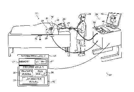
Fig. 1 is a schematic, pictorial illustration of a cardiac
3D navigation and electrophysiological signal analysis system
20, in accordance with an embodiment of the present invention.
System 20 may be configured to analyze substantially any
physiological parameter or combinations of such parameters. In
the description herein, by way of example, the signals analyzed
are assumed to be intra-cardiac (IC) and/or extra-cardiac (body
surface BS) electrocardiogram (ECG)
potential-time
relationships. In order to fully characterize such
relationships, the signals at various locations need to be
referenced in time to each other, such as is done during
generating a LAT map. The time referencing is accomplished by
measuring relative to a reference-time (e.g., instance), such
as the beginning of each QRS complex of an ECG reference signal
(i.e., the beginning of every heartbeat). The method for
generating a LAT map is described in U.S Patent 9,050,011,
cited above.
For simplicity and clarity, the following description,
except where otherwise stated, assumes an investigative
procedure wherein system 20 measures actual electrical activity
of a heart 34, using a probe 24. A distal end 32 of the probe
is assumed to have electrodes 22. The measured signals are
used, among other usages, for creating a LAT map of at least
part of wall tissue of heart 34 of a patient 26.
Typically, probe 24 comprises a catheter which is inserted
into the body of patient 26 during a mapping procedure
9
CA 3035472 2019-03-04
performed by a physician 28 using system 20. During the
procedure patient 26 is assumed to be attached to a grounding
electrode 23. In addition, electrodes 29 are assumed to be
attached to the skin of patient 26, in the region of heart 34.
System 20 may be controlled by a system processor 40,
comprising a processing unit 42 communicating with a memory 44.
In some embodiments, a memory 44, which is included in system
processor 40, stores a LAT and/or voltage map 62 of at least
part of wall tissue of heart 34 of patient 26. Additionally or
alternatively, memory 44 may store maps of other patients.
Moreover, any other processor (i.e., not necessarily part of
system 20) that comprises a memory may store one or more maps.
Processor 40 is typically mounted in a console 46, which
comprises operating controls 38, typically including a pointing
device 39 such as a mouse or trackball, that professional 28
uses to interact with the processor.
Processor 40 (specifically processing unit 42) runs
software, comprising a probe tracker module 30, an ECG module
36, and an arrhythmia simulation module comprising a LAT
analysis module 35, to operate system 20 and/or for LAT
analysis module 35 to run simulation (using LAT or adjusted LAT
maps 62 stored in memory 44) of heart pacing so as to model
arrhythmia. The simulated heart pacing might be achieved by the
physician 20 or an assistant operator clicking on the screen in
the desired location for simulated pacing or in any other
manner. Proposed areas for simulated pacing might also be
displayed by processor 40.
Results of the operations performed by processor 40 are
presented to physician 28 on a display 48, which typically
presents a graphic user interface to the physician, a visual
representation of the ECG signals sensed by electrodes 22,
CA 3035472 2019-03-04
and/or an image or map of heart 34 while it is being
investigated. In an embodiment, LAT analysis module 35 present
to the physician a LAT map updated with one or more locations
on the map where a simulated arrhythmia originated from. The
software may be downloaded to processor 40 in electronic form,
over a network, for example, or it may, alternatively or
additionally, be provided and/or stored on non-transitory
tangible media, such as magnetic, optical, or electronic
memory.
ECG module 36 is coupled to receive actual electrical
signals from electrodes 22 and electrodes 29. The module is
configured to analyze the actual signals and may present the
results of the analysis in a standard ECG format, typically a
graphical representation moving with time, on display 48.
Probe tracker module 30 typically tracks the location of
distal end 32 of probe 24, within the heart of patient 26. The
tracker module may use any method for location tracking probes
known in the art. For example, module 30 may operate a
magnetic-field based location tracking sub-system. (For
simplicity components of such sub-system are not shown in Fig.
1.)
Alternatively or additionally, tracker module 30 may track
probe 24 by measuring impedances between electrode 23,
electrodes 29 and electrodes 22, as well as the impedances to
other electrodes which may be located on the probe. (In this
case electrodes 22 and/or electrodes 29 may provide both ECG
and location tracking signals.) The Carto3 system produced by
Biosense Webster (Irvine, California) uses both magnetic field
location tracking and impedance measurements for location
tracking.
11
CA 3035472 2019-03-04
Using tracker module 30 processor 40 is able to measure
locations of distal end 32. In addition, using both tracker
module 30 and ECG module 36 the processor is able to measure
locations of the distal end, as well as LATs of the actual
electrical signals detected at these particular locations. For
clarity, in the present disclosure and in the claims, measured
locations of the distal end that do not have associated LAT
measurements are herein termed non-LAT-locations, and are used
only for generating the anatomical component of a three-
dimensional (3D) LAT map of interior walls tissue of heart 34.
Measured locations of the distal end having respective LAT
measurements are termed LAT-locations, and are subsequently
used for attempting simulating an arrhythmia.
SIMULATION OF HEART PACING FOR MODELING ARRHYTHMIA
Fig. 2 is a schematic, pictorial illustration of LAT map
62 of heart 34, in accordance with an embodiment of the present
invention. For simplicity, only a portion of a complete map of
interior walls tissue is shown in Fig. 2. LAT map 62 is
formulated as a mesh comprising a multitude of non-LAT-location
points 64, the positions of which have been evaluated by
tracker module 30 so as to create the anatomical component of
map 62. In an embodiment, processor 40 connects points 64 by
straight inter-point lines 66 so as to form a mesh of connected
planar triangles 70. Connected triangles 70 form a surface that
approximates the heart interior wall tissue surface. Other
methods of anatomical reconstruction may be applied, such as
CARTO SEG CT/MRI imports, and other modes of presentation of
the reconstruction may be used, such a mesh produced from fast-
anatomical-mapping.
12
CA 3035472 2019-03-04
Map 62 also shows LAT-locations 68, each LAT-location
having an associated LAT value (referred to simply as "LAT").
Typically, LAT-locations and their associated LATs are
evaluated at a different time period from the time used by
processor 40 to generate the anatomical component of map 62. As
for non-LAT-locations, LAT-locations are adjusted to the
reference-time, among other reasons so as to correct for heart
wall motion. In principle, LAT-locations 68 should be
registered with surfaces of triangles 70, since both types of
locations, LAT-locations and non-LAT-locations, should lie on
the heart tissue wall.
The electrical activity of the heart may be thought of as
a wave of electrical potential, which initiates at the
beginning of every heartbeat at the sinus node, and which
propagates through the cardiac muscle. At any point on a cavity
wall of the heart, a LAT at that point is caused by the
potential propagating past the point.
In LAT map 62, one or more LAT-locations 68A designate
actual signal pacing locations, i.e., locations at which an
actual electrical signal was injected by a catheter electrode
22 into the heart wall tissue in the process of creating the
map. LAT-locations 68B designate measured locations where the
resulting electrical activity (in response to the injected
actual signal) were sensed, so as to measure the respective LAT
values.
In an embodiment, LAT analysis module 35 applies
simulated electrical activity propagation in order to identify
by simulation of this electrical activity propagation,
virtually paced locations 68A, which provide best temporal fit,
between resulting (i.e., by the simulation) simulated LAT
patterns at different locations 68B, and a recorded clinical
13
CA 3035472 2019-03-04
arrhythmia. For example, a best fit may be obtained between a
virtual pacing resulting in virtual LAT map and virtual time
interval and time intervals characteristic of the recorded
arrhythmia.
In some embodiments, LAT analysis module 35 updates LAT
map 62 during simulated stimulation with one or more locations
estimated as potential sources of arrhythmia. LAT analysis
module 35 further assigns grades to LAT locations that quantify
a likelihood of these candidate locations being sources of the
arrhythmia. LAT analysis module 35 numerically and/or
graphically updates LAT map 62 with the grades attributed to
the one or more locations. Simulated pacing locations 68A that
receive highest grades may serve as priority locations for
attempts by the physician, during a catheterization, to
generate acquired signals that correspond to the recorded
arrhythmia. Subsequently, the physician may ablate tissue in
vicinity of clinically identified locations, so as to for
example isolate such.
Fig. 3 is a flow chart that schematically illustrates a
method for identifying on LAT map 62, locations that an
arrhythmia may initiate from, in accordance with an embodiment
of the invention. The locations are identified by creating
simulated activation generated by virtual pacing, which yield
results based on the pre-collected electro-anatomical signals.
The procedure may begin with, based on measured LAT map
62, building LAT map or adjusted LAT map, in which analysis
module 35 calculates all LAT data and places it on map 62
stored in memory 44, at an initial step 70. Next, at a step 72,
a virtual source 68A (i.e., an initial point of simulated
pacing) is chosen by the processor or the user. LAT analysis
14
CA 3035472 2019-03-04
module 35 considers the real propagation data and calculates
the propagation from the virtual source at step 74.
The method now proceeds to an analyzing step 76, in which
LAT analysis module 35 assign grades to a specific pacing
position 68A that quantify a likelihood of the candidate
location being source of the arrhythmia. In an embodiment, LAT
analysis module 35 adds an indication, such as the grade or a
graphical one, to LAT map 62, at an updating map step 78.
The procedure may be repeated by LAT analysis module 35
selecting another virtually paced location 68A, as the method
returns to selecting initial point step 72.
The example flow chart shown in Fig. 3 is chosen purely
for the sake of conceptual clarity. In alternative embodiments,
various steps may be performed to assess locations of
arrhythmia such as using alternative electrophysiological maps
and/or simulation steps as well as performing the above in a
different order.
Although the embodiments described herein mainly address
the treatment of ischemic ventricular tachycardia, the methods
and systems described herein can also be used in other
applications, such as in any focal or reentrant arrhythmias.
It will thus be appreciated that the embodiments described
above are cited by way of example, and that the present
invention is not limited to what has been particularly shown
and described hereinabove. Rather, the scope of the present
invention includes both combinations and sub-combinations of
the various features described hereinabove, as well as
variations and modifications thereof which would occur to
persons skilled in the art upon reading the foregoing
description and which are not disclosed in the prior art.
Documents incorporated by reference in the present patent
CA 3035472 2019-03-04
application are to be considered an integral part of the
application except that to the extent any terms are defined in
these incorporated documents in a manner that conflicts with
the definitions made explicitly or implicitly in the present
specification, only the definitions in the present
specification should be considered.
16
CA 3035472 2019-03-04