Note: Descriptions are shown in the official language in which they were submitted.
CA 03035610 2019-03-01
WO 2018/068849
PCT/EP2016/074497
1
ROTARY VALVE DEVICE AND LIQUID LIFTING DEVICE COMPRISING
THE SAME
Technical Field
The present disclosure generally relates to a rotary valve device. In
particular, a rotary valve device for sequentially connecting a first line to
a plurality of second lines, a rotary valve assembly comprising two such
rotary valve devices, a lifting device comprising the rotary valve device, a
lifting device comprising the rotary valve assembly and methods of
controlling the lifting devices, are provided.
Background
In a wide range of applications, it is desired to elevate a liquid from a
lower reservoir to a higher or upper reservoir which is vertically above
the lower reservoir. One example of such application is an elevated
reservoir for fish cultivation, where unused sea water is supplied from a
.. lower reservoir to the elevated reservoir and used sea water (e.g. with
less oxygen gas) is drained from the elevated reservoir back to the lower
reservoir. Further applications include cooling installations for power
production, process industry, oil rigs, ships and similar.
US 2002106291 Al discloses a pumping unit for water supply in remote
.. areas of the world. The pumping unit is used to pump water from a sump
to a storage tank above the pumping unit. The pumping unit comprises a
pump, a control valve and a tipping bucket mechanism.
PCT/EP2015/073298 filed by Energy Harvest AS discloses a lifting device
for vertically lifting liquids. The lifting device comprises a lifting line
arrangement for guiding a liquid from a lower reservoir to an upper
reservoir, a lowering line arrangement for guiding the liquid from the
upper reservoir to the lower reservoir, a pressure converter configured to
convert a liquid pressure in the lowering line arrangement into a liquid
pressure in the lifting line arrangement.
CA 03035610 2019-03-01
WO 2018/068849
PCT/EP2016/074497
2
Summary
Conventional three-way valves may be difficult to accurately control to
deliver a specific flow, such as a charge flow to the pressure converter in
PCT/EP2015/073298. For example, some valves lack proportionality
between valve position and flow rate. There is also a problem with
pressure pulses due to sudden bumping of the valve into its seat, and
due to a sudden release of the valve. The reasons for this include static
friction, the forces applied, suction effects, etc. Many conventional three-
way valves that are used to direct fluid to the chambers of a cylinder
.. comprising a reciprocating piston require a control system where control
signals to the valves are calculated based on measures states of the
system including the cylinder (e.g. instrumentation to read the piston
position).
In a lifting device for vertically lifting liquids from a lower reservoir to
an
upper reservoir, it is difficult to accurately distribute the charge flow
between the two chambers of a pressure converter cylinder comprising a
reciprocating piston with conventional three-way valves, in particular
during transitions between the strokes. Conventional three-way valves
are also often subjected to a relatively high wear.
One object of the present disclosure is to provide an accurate control of
one or more displaceable members (e.g. reciprocating pistons) driven by
a fluid, in particular of displaceable members of pressure converters in a
lifting device for vertically lifting liquids from a lower reservoir to an
upper reservoir or a lowering device for vertically lowering liquids from an
upper reservoir to a lower reservoir.
A further object of the present disclosure is to provide an accurate control
of the fluid volumes delivered by, and/or received from, one or more
displaceable members, in particular displaceable members of pressure
converters in a lifting device for vertically lifting liquids from a lower
.. reservoir to an upper reservoir.
CA 03035610 2019-03-01
WO 2018/068849
PCT/EP2016/074497
3
A still further object of the present disclosure is to provide a valve device
that can control one or more fluid driven displaceable members of several
cylinders to make a continuous directional change, i.e. a continuous or
smooth change between two strokes.
A still further object of the present disclosure is to provide a valve device
having a simple and reliable design.
A still further object of the present disclosure is to provide a lifting
device
for vertically lifting liquids from a lower reservoir to an upper reservoir
having a simple and reliable design.
A still further object of the present disclosure is to provide a method that
solves at least one of the above objects.
According to one aspect, there is provided a rotary valve device for
sequentially connecting a first line to a plurality of second lines, the
rotary valve device comprising:
- a stationary structure comprising a first port for connection to the first
line and at least two second ports for connection to a respective second
line; and
- a distribution rotor rotatably arranged within the stationary structure,
the distribution rotor comprising at least one rotor opening;
wherein the rotary valve device is configured such that the rotor opening
sequentially establishes a fluid communication between the first port and
the second ports as the distribution rotor rotates.
The rotary valve enables a design where accurate flow rates and/or
accurate fluid volumes are delivered to (i.e. a charge) and/or received
from (i.e. a return) a fluid driven cylinder comprising a displaceable
member. The rotary valve device according to the present disclosure is
an alternative to three-way valves. The rotary valve device may be used
to control a lifting device, such as the lifting device developed by Energy
Harvest AS and described in international application
CA 03035610 2019-03-01
WO 2018/068849
PCT/EP2016/074497
4
PCT/EP2015/073298. However, other applications for the rotary valve
device are possible.
The rotary valve device may be configured to sequentially connect an
inlet line to a plurality of outlet lines. In other words, the first line may
be
constituted by an inlet line and the second lines may be constituted by
outlet lines. Alternatively, the rotary valve device may be configured to
sequentially connect a plurality of inlet lines to an outlet line. In other
words, the first line may be constituted by an outlet line and the second
lines may be constituted by inlet lines.
A first chamber may be in immediate fluid communication with the first
port. In case the first port is coupled to an inlet line, the first chamber
may be arranged downstream of the first port and upstream of the
distribution rotor, i.e. the first chamber may be constituted by an inlet
chamber. In case the first port is coupled to an outlet line, the first
chamber may be arranged upstream of the first port and downstream of
the distribution rotor, i.e. the first chamber may be constituted by an
outlet chamber. The rotary valve device may comprise more than one
first port and a first chamber associated with each first port. For
example, the rotary valve device may comprise two first ports and two
.. first chambers.
The rotary valve device may further comprise a second chamber having a
plurality of compartments (e.g. four), each associated with a respective
second line. The compartments may be defined by one or several
compartment walls (also forming part of the stationary structure).
In case the second ports are coupled to outlet lines, the second chamber
may be arranged upstream of the second ports and downstream of the
distribution rotor, i.e. the second chamber may be constituted by an
outlet chamber and the compartments may constitute outlet
compartments. In case the second ports are coupled to inlet lines, the
second chamber may be arranged downstream of the second ports and
upstream of the distribution rotor, i.e. the second chamber may be
CA 03035610 2019-03-01
WO 2018/068849
PCT/EP2016/074497
constituted by an inlet chamber and the compartments may constitute
inlet compartments. The first chamber and the second chamber including
the compartments may constitute the stationary structure or a part of the
stationary structure.
5 The distribution rotor may be constituted by a disk, i.e. the
distribution
rotor may have a substantially flat appearance. The rotor opening of the
distribution rotor may adopt various different designs. According to one
variant, the distribution rotor comprises only one rotor opening.
According to a further variant, the distribution rotor comprises more than
one rotor opening. Thus, the definition in that the distribution rotor
comprises a rotor opening means that the distribution rotor comprises at
least one rotor opening. The one or more rotor openings may be
designed such that any volume or flow rate profile is delivered
therethrough over time, i.e. as the distribution rotor rotates.
According to one example, the rotor opening has an increasing radial
extension. A section of the rotor opening with lower radial extension may
be arranged "in front" and a section of the rotor opening with higher
radial extension may be arranged "behind" in the rotational direction of
the distribution rotor. For example, the rotor opening may have a
generally droplet shaped appearance where the tip of the droplet "comes
first" in the rotation. In case a stator member with stator openings is
employed, the section of the rotor opening with lower radial extension
may overlap with the stator opening before the section of the rotor
opening with higher radial extension overlaps with the stator opening, as
the distribution rotor rotates.
Due to its function, the rotary valve device may alternatively be referred
to as a rotary distribution valve, rotary diverter valve or rotary sequence
valve. The stationary structure may be constituted by, or comprise, a
housing.
The distribution rotor may or may not have a uniform cross-sectional
design along the rotational axis. One example of a distribution rotor
CA 03035610 2019-03-01
WO 2018/068849
PCT/EP2016/074497
6
having such uniform cross-sectional design is a distribution rotor having a
cylindrical appearance and a rotor opening in the form of a straight hole,
i.e. parallel with, and offset from, the rotational axis of the distribution
rotor.
The rotary valve device may be configured to establish a fluid
communication between the first port and one of the second ports before
closing an established fluid communication between the first port and
another of the second ports as the distribution rotor rotates. In this
manner, if the rotary valve device is used to alternatingly deliver a
charge fluid to cylinder chambers to drive a reciprocating piston, a small
flow can be guided to the front side (as seen in the movement direction)
of the piston before the piston reaches its end position in order to damp
the piston at the end positions of the strokes. The same also applies for
displaceable members other than pistons, such as diaphragms or
membranes.
In any angular position of the distribution rotor, the rotor opening may
provide a fluid communication between the first port and one or more of
the second ports. Alternatively, or in addition, the rotary valve device
may be configured such that fluid communication between the first port
and all second ports is prevented at one or more angular positions of the
distribution rotor. This may for example be accomplished by increasing
the thickness of the compartment walls, by decreasing the length of the
rotor opening along the rotational direction (i.e. in the plane of rotation of
the distribution rotor), and/or by decreasing the length of the stator
openings along the rotational direction.
The distribution rotor may be arranged to rotate continuously. In this
manner, the start/stop nature of a conventional valve can be avoided.
According to one variant, the distribution rotor is arranged to rotate
continuously at a substantially continuous speed (e.g. with less than 5%
deviation from an average speed). In this variant, the rotary valve device
may be operated completely without any control system other than
controlling the motor on and off.
CA 03035610 2019-03-01
WO 2018/068849
PCT/EP2016/074497
7
According to one variant, the rotary valve device is configured to control
the distribution rotor to rotate with a position dependent speed. For this
purpose, a position sensor for sensing the angular position of the
distribution rotor and a drive control unit for controlling the rotational
speed of the distribution rotor based on the signals from the position
sensor, may for example be provided.
The rotor opening may comprise a radially wide portion between two
radially narrow portions along a rotational direction of the distribution
rotor. A radially wide portion has a longer radial extension than a radially
narrow portion. In this manner, a smooth opening and a smooth closing
of the of the fluid communication between the first port and the second
ports can be realized. This design also enables a smooth operation of a
displaceable member such as a piston member.
The rotor opening may comprise a radially outer profile having a shape
based on a sine function. In addition, the rotor opening may comprise a
radially inner profile having an arc shape. In such a case, the outer
profile sine shape may be relative to the arc shape.
The rotary valve device according to the present disclosure may further
comprise a stator member fixedly arranged within the stationary
structure, downstream of the distribution rotor, wherein the stator
member comprises a stator opening associated with each second port.
The stator member may, in addition to the distribution rotor, be used to
entirely or partly limit the fluid communication between the first port and
the second ports. In other words, the stator member may, together with
the distribution rotor, determine the timing and properties of flow to the
second ports (or to the compartment associated with each second port).
The stator member may be constituted by a disk, i.e. the stator member
may have a substantially flat appearance.
The rotary valve device may be configured such that a fluid
communication between the first port and one or more of the second
ports is always established as the distribution rotor rotates. That is, a
CA 03035610 2019-03-01
WO 2018/068849
PCT/EP2016/074497
8
fluid communication is established between the first port and one or more
of the second ports at each angular position of the distribution rotor.
According to a further aspect, there is provided a rotary valve assembly
comprising two rotary valve devices according to the present disclosure,
wherein the distribution rotors of the rotary valve devices are arranged to
rotate synchronously. The rotary valve assembly may be used to control
a lifting device. However, other applications for the rotary valve assembly
are possible.
Depending on the implementation, a synchronous rotation may or may
not require that the distribution rotors are in phase. The two distribution
rotors may be offset in phase, i.e. one distribution rotor may be ahead of
the other. The phase offset may for example depend on the
characteristics of an intermediate volume between the rotary valve
devices. The designs and/or dimensions of the rotor openings in the two
.. distribution rotors may be different from each other.
The rotary valve assembly may further comprise a shaft, wherein the
distribution rotors of the rotary valve devices are connected via the shaft
to rotate synchronously. The shaft may be driven by a motor. The shaft
may be fixedly connected to the two distribution rotors (i.e. to rotate in
common).
The distribution rotors of the rotary valve devices may alternatively be
driven independently, for example by means of two motors. The
distribution rotors may be synchronized by means of a standard
advanced motor control with accurate position control of the distribution
rotors.
The rotary valve assembly may further comprise a hollow shaft motor
configured to rotationally drive the shaft. The hollow shaft motor may for
example be arranged between the two rotary valve devices.
CA 03035610 2019-03-01
WO 2018/068849
PCT/EP2016/074497
9
The rotary valve devices may be connected in fluid series, wherein the
second ports of the first rotary valve device are outlet ports and the
second ports of the second rotary valve device are inlet ports.
At least two of the second ports of the first rotary valve device may be in
fluid communication with a respective second port of the second ports of
the second rotary valve device. According to one variant, each second
port of the first rotary valve device is in fluid communication with a
respective second port of the second rotary valve device. According to
one variant, at least one of the second ports of the first rotary valve
device is not in fluid communication with a second port of the second
rotary valve device. Such second port may for example be guided to a
turbine for driving the rotation of one or both of the distribution rotors.
The rotary valve devices may be configured to simultaneously fill a first
intermediate volume, between a first of the second ports of the first
rotary valve device and a first of the second ports of the second rotary
valve device, and drain a second intermediate volume, between a second
of the second ports of the first rotary valve device and a second of the
second ports of the second rotary valve device, and vice versa.
The two rotary valve devices may be stacked. In case each distribution
rotor is driven by a shaft, the shaft may protrude axially out from the
stack and there be driven by a motor, for example by a hollow shaft
motor. Stacked in this regard means that the rotary valve devices are
compactly arranged, for example within a common housing.
According to a further aspect, there is provided a lifting device for
vertically lifting liquids, the lifting device comprising a lifting line
arrangement for guiding a liquid from a lower reservoir to an upper
reservoir; a lowering line arrangement for guiding the liquid from the
upper reservoir to the lower reservoir; a pressure converter configured to
convert a liquid pressure in the lowering line arrangement into a liquid
pressure in the lifting line arrangement, the pressure converter
comprising a hollow body and a displaceable member movable within the
CA 03035610 2019-03-01
WO 2018/068849
PCT/EP2016/074497
hollow body in order to substantially sealingly divide the hollow body into
two chambers of variable volumes; and a rotary valve device according
to the present disclosure; wherein the first port is in fluid communication
with the lowering line arrangement, upstream of the pressure converter,
5 and two of the second ports are in fluid communication with a respective
chamber of the pressure converter. Throughout the present disclosure, a
displaceable member may be constituted by a piston member. However,
a displaceable member may alternatively be constituted by a diaphragm
or a membrane.
10 .. The lifting device may be arranged such that during one rotation of the
distribution rotor, the displaceable member makes two strokes, one in
each direction, within the hollow body. Hence, the rotary valve device
may in this case comprise only two second ports.
The lifting device may allow liquid (e.g. water) to be circulated in a
continuous loop formed by the lower reservoir, the lifting line
arrangement, the upper reservoir and the lowering line arrangement. The
liquid thereby returns to the lower reservoir from which it has been
originally pumped. Thus, within the present disclosure, the lower
reservoir may be constituted by one single reservoir.
However, it is possible that the lower reservoir is constituted by two
reservoirs, e.g. a first lower reservoir and a second lower reservoir. The
second lower reservoir may be below the first lower reservoir. In this
case, the lifting line arrangement may be configured to guide a liquid
from the first lower reservoir to the upper reservoir and the lowering line
arrangement may be configured to guide the liquid from the upper
reservoir to the second lower reservoir. Both the first lower reservoir and
the second lower reservoir may be open to the surrounding atmosphere.
The weight of the liquid head inside the lowering line arrangement above
the pressure converter imposes a static force on the displaceable
member. Due to this gravital force, the displaceable member is forced to
move to impose a corresponding upwardly directed pressure on the liquid
CA 03035610 2019-03-01
WO 2018/068849
PCT/EP2016/074497
11
in the lifting line arrangement, for example by means of a further
displaceable member. Since potential energy of the liquid in the lowering
line arrangement is "collected" and used to pump the liquid in the lifting
line arrangement upwardly towards the upper reservoir, the lifting device
resembles a U-pipe even when being used with an open lower reservoir.
The lifting device thereby also functions as an energy recovery apparatus
or an energy harvester.
A pressure converter according to the present disclosure may comprise
two hollow bodies and a displaceable member (e.g. a reciprocating piston
member) arranged within each hollow body. The displaceable members
may for example be rigidly coupled by means of a piston rod for a
common reciprocation. The hollow body in fluid communication with the
rotary valve device may be a lowering hollow body (e.g. through which
fluid in the lowering line arrangement is guided) and the other hollow
body may be a lifting hollow body (e.g. through which in the lifting line
arrangement is pumped).
At each end position, where the displaceable members change directions,
the flow delivered by the displaceable member in the lifting hollow body
will be zero. When the coupled displaceable members start to accelerate
from an end position, the flow rate will increase until a stable flow rate is
reached. During the main stroke (e.g. during a major part of the distance
moved by the piston member, or by a central portion of a membrane or
diaphragm), the flow is stable. When the displaceable members start to
decelerate as they approach the opposite end position, the flow rate will
decrease until zero. Hence, this type of lifting device will have a variable
flow. If the lifting device comprises only one such pressure converter, the
speed of the displaceable members will unavoidably vary when
accelerating and decelerating to change stroke direction.
Instead of a lifting device according to the present disclosure, a lowering
device for vertically lowering liquids may be used. The lowering device
may be configured to vertically lower liquids from an upper volume or
reservoir where the liquid has a relatively low pressure to a lower volume
CA 03035610 2019-03-01
WO 2018/068849
PCT/EP2016/074497
12
or reservoir where the liquid has a relatively high pressure. The upper
volume and the lower volume may for example be constituted by
volumes at different depths.
In such lowering device, each pressure converter may be configured to
convert a liquid pressure in a lifting line arrangement into a liquid
pressure in a lowering line arrangement. Thus, instead of using the
gravital force of a liquid head inside the lowering line arrangement, as in
the lifting device, the lowering device can use of the higher pressure in
the lifting line arrangement. In other words, the lifting device lifts liquids
against the gravital force while the lowering device lowers liquids against
a counter force, e.g. a height difference between two liquid volumes.
A lifting device and a lowering device according to the present disclosure
may be collectively referred to as a device for vertically pumping liquids.
Unless otherwise indicated, a lowering device may have a reverse
configuration and operation with respect to a lifting device.
According to a further aspect, there is provided a lifting device for
vertically lifting liquids, the lifting device comprising a lifting line
arrangement for guiding a liquid from a lower reservoir to an upper
reservoir; a lowering line arrangement for guiding the liquid from the
upper reservoir to the lower reservoir; a plurality of pressure converters,
each configured to convert a liquid pressure in the lowering line
arrangement into a liquid pressure in the lifting line arrangement,
wherein each pressure converter comprises a hollow body and a
displaceable member movable within the hollow body in order to
substantially sealingly divide the hollow body into two chambers of
variable volumes; and a rotary valve device according to the present
disclosure; wherein the first port is in fluid communication with the
lowering line arrangement, upstream of the pressure converters, and two
of the second ports are in fluid communication with a respective chamber
of each pressure converter. The plurality of pressure converters may be
fluidically parallel.
CA 03035610 2019-03-01
WO 2018/068849
PCT/EP2016/074497
13
The definition in that two of the second ports are in fluid communication
with a respective chamber of each pressure converter means that a first
second port of a first pair of second ports is in fluid communication with a
first chamber of a first pressure converter, a second second port of the
first pair of second ports is in fluid communication with a second chamber
of the first pressure converter, a first second port of a second pair of
second ports is in fluid communication with a first chamber of a second
pressure converter, and a second second port of the second pair of
second ports is in fluid communication with a second chamber of the
second pressure converter etc.
In case a plurality of pressure converters are provided, the flow rate of
the liquid in the lifting line arrangement, pumped by the plurality of
pressure converters to the upper reservoir, can be made stable, i.e.
fluctuations in flow and pressure can be eliminated. In this lifting device,
the rotary valve device may be driven without control system.
According to one variant, the lifting device comprises two pressure
converters. According to a further variant, the lifting device comprises
more than two pressure converters, such as for example four, eight,
twelve or twentyfour pressure converters. If the lifting device comprises
more than two pressure converters, one or more pressure converters
may be taken out of service while maintaining a stable flow. One or more
of the pressure converters may serve as backup, either temporarily or
permanent.
A lifting device comprising a plurality of pressure converters might still
generate some pressure pulsations and flow variations. However, the
more pressure converters that are provided, the lesser the pulsations and
flow variations become. Additionally, one or more pressure dampeners
may be installed in the lifting device. These may be of any known type.
Throughout the present disclosure, a lifting device comprising only one
pressure converter may be referred to as a single energy harvest
CA 03035610 2019-03-01
WO 2018/068849
PCT/EP2016/074497
14
configuration and a lifting device comprising a two pressure converters
may be referred to as a dual energy harvest configuration.
According to a further aspect, there is provided a lifting device for
vertically lifting liquids, the lifting device comprising a lifting line
arrangement for guiding a liquid from a lower reservoir to an upper
reservoir; a lowering line arrangement for guiding the liquid from the
upper reservoir to the lower reservoir; a pressure converter configured to
convert a liquid pressure in the lowering line arrangement into a liquid
pressure in the lifting line arrangement, the pressure converter
comprising a hollow body and a displaceable member movable within the
hollow body in order to substantially sealingly divide the hollow body into
two chambers of variable volumes; and a rotary valve assembly
according to the present disclosure; wherein the first port of the first
rotary valve device is in fluid communication with the lowering line
arrangement, upstream of the pressure converter, two of the second
ports of the first rotary valve device are in fluid communication with a
respective chamber of the pressure converter, two of the second ports of
the second rotary valve device are in fluid communication with a
respective chamber of the pressure converter, and the first port of the
second rotary valve device is in fluid communication with the lowering
line arrangement, downstream of the pressure converter.
According to a further aspect, there is provided a lifting device for
vertically lifting liquids, the lifting device comprising a lifting line
arrangement for guiding a liquid from a lower reservoir to an upper
reservoir; a lowering line arrangement for guiding the liquid from the
upper reservoir to the lower reservoir; a plurality of pressure converters,
each configured to convert a liquid pressure in the lowering line
arrangement into a liquid pressure in the lifting line arrangement, each
pressure converter comprising a hollow body and a displaceable member
movable within the hollow body in order to substantially sealingly divide
the hollow body into two chambers of variable volumes; and a rotary
valve assembly according to the present disclosure; wherein the first port
CA 03035610 2019-03-01
WO 2018/068849
PCT/EP2016/074497
of the first rotary valve device is in fluid communication with the lowering
line arrangement, upstream of the pressure converters, two of the
second ports of the first rotary valve device are in fluid communication
with a respective chamber of each pressure converter, two of the second
5 ports of the second rotary valve device are in fluid communication with a
respective chamber of each pressure converter, and the first port of the
second rotary valve device is in fluid communication with the lowering
line arrangement, downstream of the pressure converters.
According to a further aspect, there is provided a method of controlling a
10 lifting device according to the present disclosure, the method
comprising
in a first sequence, sequentially establishing a fluid communication
between the first port and each of the second ports associated with the
first chamber of each pressure converter by rotating the distribution
rotor; and in a second sequence, following the first sequence,
15 sequentially establishing a fluid communication between the first port
and
each of the second ports associated with the second chamber of each
pressure converter by rotating the distribution rotor.
According to a further aspect, there is provided a method of controlling a
lifting device according to the present disclosure, the method comprising
in a first opening sequence, sequentially establishing a fluid
communication between the first port of the first rotary valve device and
each of the second ports of the first rotary valve device associated with
the first chamber of each pressure converter by rotating the distribution
rotor; and in a second opening sequence, following the first opening
sequence, sequentially establishing a fluid communication between the
first port of the first rotary valve device and each of the second ports of
the first rotary valve device associated with the second chamber of each
pressure converter by rotating the distribution rotor.
The method may further comprise in a first closing sequence,
sequentially closing a fluid communication between the second port of
the second rotary valve device associated with the first chamber of each
pressure converter by rotating the distribution rotor; and in a second
CA 03035610 2019-03-01
WO 2018/068849
PCT/EP2016/074497
16
closing sequence, following the first closing sequence, sequentially
closing a fluid communication between the second port of the second
rotary valve device associated with the second chamber of each pressure
converter by rotating the distribution rotor.
The first opening sequence and the first closing sequence may be carried
out simultaneously, and the second opening sequence and the second
closing sequence may be carried out simultaneously, such that a fluid
communication between the first port of the first rotary valve device and
the second port of the first rotary valve device associated with the first
chamber of one pressure converter is established substantially at the
same time as the fluid communication between the second port of the
second rotary valve device associated with the first chamber of the
pressure converter and the first port of the second rotary valve device is
closed.
Brief Description of the Drawings
Further details, advantages and aspects of the present disclosure will
become apparent from the following embodiments taken in conjunction
with the drawings, wherein:
Fig. 1: schematically represents front views of some components of a
rotary valve device;
Fig. 2: schematically represents a cross-sectional side view of the
rotary valve device;
Fig. 3: shows an example of flow pattern of the rotary valve device in
Fig. 2;
Fig. 4: schematically represents a shape of a rotor opening and a
stator opening;
Fig. 5 schematically represents different angular positions of the
rotor opening relative to the stator opening;
Fig. 6: schematically represents a rotary valve assembly comprising
two rotary valve devices;
Fig. 7: schematically represents an exploded perspective view of some
CA 03035610 2019-03-01
WO 2018/068849
PCT/EP2016/074497
17
components of a further rotary valve assembly comprising two
rotary valve devices;
Fig. 8: schematically represents a perspective view of some
components of the rotary valve assembly in Fig. 7 in an
assembled state;
Fig. 9: schematically represents a perspective and partially cut out
view of some components of the rotary valve assembly in Figs.
5 and 6;
Fig. 10: schematically represents a lifting device comprising two rotary
valve devices and one pressure converter;
Fig. 11: shows an example of flow pattern of the rotary valve devices in
Fig. 10;
Fig. 12: schematically represents a lifting device comprising two rotary
valve devices and two pressure converters; and
Fig. 13: shows an example of flow pattern of the rotary valve devices in
Fig. 12.
Detailed Description
In the following, a rotary valve device for sequentially connecting a first
line to a plurality of second lines, a rotary valve assembly comprising two
such rotary valve devices, a lifting device comprising the rotary valve
device, a lifting device comprising the rotary valve assembly and
methods of controlling the lifting devices, will be described. The same
reference numerals will be used to denote the same or similar structural
features.
Fig. 1 schematically represents front views of some components of a
rotary valve device 10. The rotary valve device 10 of this example
comprises a stationary structure 12, a distribution rotor 14 and a stator
member 16. A first part (the leftmost in Fig. 1) of the stationary structure
12 forms a first chamber and comprises a first port 18 for connection to a
first line or conduit for fluid communication into or out from the first
chamber.
CA 03035610 2019-03-01
WO 2018/068849
PCT/EP2016/074497
18
The distribution rotor 14 is here implemented as a substantially flat and
circular disk. A rotor opening 20 is provided in the distribution rotor 14
and extends fully therethrough. In this implementation, the rotor opening
20 has an elongated curved profile that extends approximately 700 along
the rotational direction 22.
The stator member 16 comprises a plurality of stator openings, generally
designated 24. In Fig. 1, the stator member 16 comprises four stator
openings 24a, 24b, 24c, 24d. In this implementation, the stator member
16 is a substantially flat disk and the stator openings 24 are circular
through holes. The stator member 16 may be fixedly attached to the
stationary structure 12 or may be integrally formed with the stationary
structure 12.
A second part (the rightmost in Fig. 1) of the stationary structure 12
forms a second chamber which is divided into four compartments 26a,
26b, 26c, 26d by means of compartment walls 28. The stationary
structure 12 comprises a plurality of second ports, generally designated
30. In this example, the stationary structure 12 comprises four second
ports 30a, 30b, 30c, 30d. Each stator opening 24a, 24b, 24c, 24d of the
stator member 16 is associated with a respective compartment 26a, 26b,
26c, 26d and a respective second port 30a, 30b, 30c, 30d.
The rotary valve device 10 may comprise additional components than
shown in Fig. 1. It should also be noted that the stator member 16 may
be omitted.
Fig. 2 schematically represents a cross-sectional side view of the rotary
valve device 10. In Fig. 2, it can be seen how the first part (the leftmost
in Fig. 2) of the stationary structure 12 forms the first chamber 32 and
how the second part (the rightmost in Fig. 2) of the stationary structure
12 forms the second chamber comprising the compartments 26a, 26b,
26c, 26d (only two are visible in Fig. 2) defined by the compartment
walls 28.
CA 03035610 2019-03-01
WO 2018/068849
PCT/EP2016/074497
19
The distribution rotor 14 is rotatably arranged within the stationary
structure 12. In this example, the stationary structure 12 is implemented
as a housing.
Fig. 2 further shows that the first port 18 can be coupled to a first line 34
and that each second port 30a, 30b, 30c, 30d (only two are visible in Fig.
2) can be coupled to a respective second line 36a, 36b, 36c, 36d (only
two are visible in Fig. 2). The second lines 36a, 36b, 36c, 36d are
generally designated 36. As illustrated with the arrows, the first line 34 is
an inlet line and the second lines 36a, 36b, 36c, 36d are outlet lines in
this implementation. However, the reverse configuration is possible which
will be described in the following.
The rotary valve device 10 further comprises shaft 38. The shaft 38 is
fixedly coupled to the distribution rotor 14 and the two parts rotate
together about a rotational axis 40. As the distribution rotor 14 rotates,
the rotor opening 20 becomes aligned with one of the stator openings
24a, 24b, 24c, 24d and thereby sequentially connects the first chamber
32 to one of the compartments 26a, 26b, 26c, 26d. As a consequence,
the rotary valve device 10 sequentially establishes a fluid communication
between the first port 18 and one of the second ports 30a, 30b, 30c, 30d.
Fig. 3 shows an example of flow pattern of the rotary valve device 10 in
Fig. 2. Four strokes are generated as the distribution rotor 14 rotates
360 . The flow rate is determined by the geometry of the rotor opening
20 of the distribution rotor 14. The example is not according to the
geometry in Fig. 1.
In the first stroke, the rotor opening 20 is aligned with the compartment
26a such that the fluid is allowed to flow from the first port 18 to the
second port 30a. In the second stroke, the rotor opening 20 is aligned
with the compartment 26b such that the fluid is allowed to flow from the
first port 18 to the second port 30b, the opening between the first port
18 and the second port 30a is closed and the fluid remaining inside the
compartment 26a may be drained. As an alternative to draining, the fluid
CA 03035610 2019-03-01
WO 2018/068849
PCT/EP2016/074497
may be kept within the compartment 26a for some time and a pressure
buildup may be established.
In the third stroke, the rotor opening 20 is aligned with the compartment
26c such that the fluid is allowed to flow from the first port 18 to the
5 second port 30c, the opening between the first port 18 and the second
port 30b is closed and the fluid remaining inside the compartment 26b is
drained. In the fourth stroke, the rotor opening 20 is aligned with the
compartment 26d such that the fluid is allowed to flow from the first port
18 to the second port 30d, the opening between the first port 18 and the
10 second port 30c is closed and the fluid remaining inside the compartment
26c is drained. When the first stroke is carried out anew, the rotor
opening 20 is aligned with the compartment 26a such that the fluid is
allowed to flow from the first port 18 to the second port 30a, the opening
between the first port 18 and the second port 30d is closed and the fluid
15 remaining inside the compartment 26d is drained.
Draining of the compartments 26a, 26b, 26c, 26d may be accomplished
by means of gravity. For this purpose, the rotary valve device 10 may be
oriented such that the rotational axis 40 comprises a directional
component in the vertical direction. The rotational axis 40 may for
20 example be substantially vertically oriented. Alternatively, the second
ports 30a, 30b, 30c, 30d may be arranged in a lower region of the
respective compartment 26a, 26b, 26c, 26d to effect the draining.
In the above flow pattern example, the rotor opening 20 is relatively
short and thereby directs a fluid flow from the first port 18 to one of the
second ports 30a, 30b, 30c, 30d. However, the rotor opening 20 may be
extended (and/or the compartment walls 28 may be made thinner and/or
the stator openings 24a, 24b, 24c, 24d may be made bigger) to cover
several compartments 26a, 26b, 26c, 26d, i.e. such that the rotor
opening 20 directs a fluid flow from the first port 18 to two adjacent
second ports 30a, 30b, 30c, 30d during transitions between one, some or
all of the strokes. Also in this variant, the rotor opening 20 sequentially
establishes a fluid communication between the first port 18 and the
CA 03035610 2019-03-01
WO 2018/068849
PCT/EP2016/074497
21
second ports 30a, 30b, 30c, 30d. The distribution rotor 14 and the stator
member 16 may be designed in various forms to create advanced flow
rate patterns between the first port 18 and the second ports 30a, 30b,
30c, 30d as the distribution rotor 14 rotates within the stationary
structure 12.
Fig. 4 schematically represents a shape of a rotor opening 20 for a
distribution rotor 14 (not shown in Fig. 4) according to the present
disclosure. With reference to Fig. 4, the shape of the rotor opening 20 will
be described. The illustrated shape of the rotor opening 20 may also be
used for the stator opening 24. In this case, also the size of the rotor
opening 20 and the size of the stator opening 24 may be the same.
The rotor opening 20 comprises a centre portion that is relatively long in
the radial direction and two outer portions that are relatively short in the
radial direction. The rotor opening 20 thus comprises a radially wide
portion between two radially narrow portions along a rotational direction
of the distribution rotor 14.
The rotor opening 20 comprises a radially outer profile having a shape
based on a sine function and a radially inner profile having an arc shape.
In this way, it is possible to generate a flow area with a sine shape as the
distribution rotor 14 rotates.
Figs. 5a to 5f schematically represents different angular positions of the
rotor opening 20 relative to the stator opening 24 during rotation of the
distribution rotor 14. In Fig. 5a, there is no overlap between the rotor
opening 20 and the stator opening 24. Consequently, no fluid
communication is established between the first port 18 and the second
port 30 associated with the stator opening 24.
In Fig. 5b, the rotor opening 20 has rotated into a position where a
radially narrow outer portion of the rotor opening 20 overlaps with a
radially narrow outer portion of the stator opening 24. As a consequence,
CA 03035610 2019-03-01
WO 2018/068849
PCT/EP2016/074497
22
a fluid communication between the first port 18 and the second port 30
associated with the stator opening 24 is established.
In Fig. 5c, the area of the overlap has increased until a full overlap is
reached, as illustrated in Fig. 5d, where the rotor opening 20 and the
.. stator opening 24 are aligned. In Figs. 5e and 5f, the area of the overlap
decreases due to the continuing rotation of the rotor opening 20 until the
fluid communication between the first port 18 and the second port 14
associated with the stator opening 24 is closed.
With this design of the rotor opening 20 and the stator opening 24, a
smooth opening and a smooth closing of the of the fluid communication
between the first port 18 and the second ports 30 can be realized. A
smooth flow is also generated during the period when the fluid
communication is established between the first port 18 and the second
port 30 associated with the stator opening 24. A relatively large
overlapping area between the rotor opening 14 and the stator opening 24
can also be maintained over a longer time. This design enables a smooth
operation of a displaceable member (shown in the following) and a more
accurate control of flows.
The distribution rotor 14 may comprise one or several, such as two or
three, rotor openings 20 shown in Fig. 4 and the stator member 16 may
comprise a corresponding amount of stator openings 24.
Fig. 6 schematically represents a rotary valve assembly 42 comprising
two rotary valve devices 10, 44. The rotary valve device 10 is of the
same type as in Fig. 2, i.e. the first port 18 is adapted for connection to a
first line 34 in the form of an inlet line and the second ports 30a, 30b,
30c, 30d are adapted for connection to second lines 36a, 36b, 36c, 36d in
the form of outlet lines. The rotary valve assembly 42 may be used to
control a lifting device comprising a plurality of pressure converters, as
will be described below.
CA 03035610 2019-03-01
WO 2018/068849
PCT/EP2016/074497
23
Similarly to the rotary valve device 10, the rotary valve device 44 also
comprises a stationary structure 46, a first port 48, second ports 50a,
50b, 50c, 50d, (generally designated 50), a distribution rotor 52 having a
rotor opening 54, a stator member 56 having stator openings 58a, 58b,
58c, 58d (generally designated 58), a first chamber 60, and a second
chamber having compartments 62a, 62b, 62c, 62d (generally designated
62).
In the rotary valve assembly 42 of Fig. 6, the rotary valve device 44 is
reversely configured with respect to the rotary valve device 10, i.e. the
first port 18 is adapted for connection to a first line 64 in the form of an
outlet line and the second ports 50a, 50b, 50c, 50d (only two are shown)
are adapted for connection to second lines 66a, 66b, 66c, 66d (only two
are shown) in the form of inlet lines. The second lines 66a, 66b, 66c, 66d
are generally designated 66. The area of each second line 66 should not
exceed the area of an associated second line 36. Preferably, the area of
each second line 66 is the same as the area of an associated second line
36.
In each rotary valve device 10, 44, the stator member 16, 56 is arranged
downstream of the distribution rotor 14, 52. However, in the rotary valve
device 10, the distribution rotor 14 is arranged between the first port 18
and the stator member 16 and in the rotary valve device 44, the stator
member 56 is arranged between the distribution rotor 52 and the first
port 48.
As shown in Fig. 6, the two distribution rotors 14, 52 are fixedly
connected to the shaft 38 and the three parts rotate together about the
rotational axis 40. The rotary valve assembly 42 further comprises a
hollow shaft motor 68 for rotationally driving the shaft 38. The hollow
shaft motor 68 is arranged between the two rotary valve devices 10, 44.
The rotational speed of the shaft 38 may be constant. However, there
might be situations where different speed settings at different angular
positions around the rotational axis 40 is beneficiary. This could be used
CA 03035610 2019-03-01
WO 2018/068849
PCT/EP2016/074497
24
as a measure to fine tune hydro-dynamic behaviour on a pressure
on
For example, if pressure pulsations occur in an installed pressure
converter, or if there are problems with the strokes due to overfilled or
underfilled chambers in the pressure converters, the rotational speed of
the shaft 38 can be adjusted (in theory to zero speed) to allow for
shorter or longer fluid communication periods for a connection between a
first port 18, 48 and a certain second port 30a, 30b, 30c, 30d, 50a, 50b,
50c, 50d. This control may be applied to only one of the rotary valve
devices 10, 44 or to both of the rotary valve devices 10, 44. According to
one variant, the control comprises one particular rotational speed target
value for each angular position around the full rotation.
This control may be implemented by known motor drive control systems
such as SCR (Silicon Controlled Rectifier) or VFD (Variable Frequency
Drive). As one example, a speed setting, e.g. for each degree around the
full rotation can be programmed and these settings can be derived from
mathematical calculations.
As a further example, an offset curve for speed settings around the full
rotation can be applied. This offset curve can be, or be derived from, a
log from operation of the system (e.g. a lifting device according to the
present disclosure). One way to establish such offset curve is to
permanently or temporarily install a flow meter in the fluid loop, and
record the flow values together with the position of the motor 68 and/or
the shaft 38. By subtracting the ideal flow rate around the rotation, the
resulting curve will be the offset curve. The same can be done with e.g.
pressure measurements instead of flow measurements, but this will
require more calculation steps to establish the offset curve.
As a further example, offset information can be fed directly to a rotational
control device. This is a real-time version of the previous method, where
measurements are used directly as a speed offset setting (raw or after
calculations).
CA 03035610 2019-03-01
WO 2018/068849
PCT/EP2016/074497
Fig. 7 schematically represents an exploded perspective view of some
components of a further rotary valve assembly 42 comprising two rotary
valve devices 10, 44. In Fig. 7, it can be gathered that the first chamber
32 of the rotary valve device 10 comprises four first chamber openings
5 70a, 70b, 70c, 70d (only two are shown). Each first chamber opening
70a, 70b, 70c, 70d is substantially aligned with a respective stator
opening 24a, 24b, 24c, 24d (only two are shown) of the stator member
16. The first chamber 60 of the rotary valve device 44 also comprises
four first chamber openings (not shown) associated with the stator
10 openings 58a, 58b, 58c, 58d of the stator member 56.
Fig. 7 further shows that the rotor openings 20, 54 of the rotary valve
devices 10, 44 have a generally droplet shaped appearance where the tip
of the droplet "comes first" in the rotation direction 22. Moreover, it can
be seen that each of the distribution rotors 14, 52 and the stator
15 .. members 16, 56 are disks having a substantially flat appearance. In this
example, each disk has a diameter that is approximately four times its
thickness (along the rotational axis 40). However, the thicknesses may
be varied depending on the implementation. The compartment walls 28
are substantially perpendicular to each other.
20 .. Fig. 8 schematically represents a perspective view of some components
of the rotary valve assembly 42 in Fig. 7 in an assembled state. In Fig. 8,
the rotary valve devices 10, 44 are stacked in a compact configuration.
The shaft 38 protrudes from one side of the stack, i.e. from the side
where the rotary valve device 10 is arranged. The distribution rotors 14,
25 .. 52 are fixedly connected to the shaft 38 for a common rotation around
the rotational axis 40. The shaft 38 may be driven by a motor (not
shown), such as the hollow shaft motor 68. The two rotary valve devices
10, 44 may be arranged within a common housing.
Fig. 9 schematically represents a perspective and partially cut out view of
some components of the rotary valve assembly 42 in Figs. 7 and 8. Each
of these rotary valve devices 10, 44 is similar to Fig. 2 in that the first
port 18 of the rotary valve device 10 is connected to a first line 34 in the
CA 03035610 2019-03-01
WO 2018/068849
PCT/EP2016/074497
26
form of an inlet line, the second ports 30a, 30b, 30c, 30d (only two are
shown) of the first rotary valve device 10 are connected to a respective
second line 36a, 36b, 36c, 36d in the form of outlet lines, the first port
48 of the rotary valve device 44 is connected to a first line 64 in the form
of an inlet line and the second ports 50a, 50b, 50c, 50d (only two are
shown) of the rotary valve device 44 is connected to a plurality of second
lines 66a, 66b, 66c, 66d (only two are shown) in the form of outlet lines.
The rotary valve device 10 in Fig. 9 is also similar to Fig. 2 in that it
comprises a second chamber having a plurality of compartments divided
by compartment walls 28. However, the rotary valve device 44 in Fig. 9
differs from the rotary valve device 10 in Fig. 2 in that it does not
comprise such second chamber. Instead, the second ports 50a, 50b, 50c,
50d are directly attached to a respective associated stator opening 58a,
58b, 58c, 58d of the stator member 56. Fig. 9 further shows four first
chamber openings 72a, 72b, 72c, 72d (only two are denoted) of the first
chamber 60 of the rotary valve device 44.
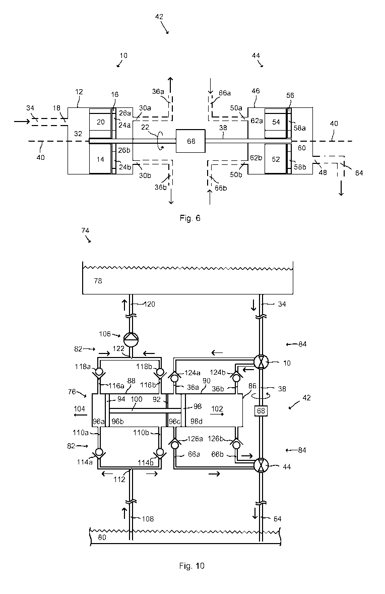
Fig. 10 schematically represents a lifting device 74 comprising a pressure
converter 76 and a rotary valve assembly 42 substantially in accordance
with Fig. 6 having two rotary valve devices 10, 44. The rotary valve
devices 10, 44 however differ by comprising only two second ports 30a,
30b, 50a, 50b (not shown). In Fig. 10, the lifting device 74 is in operation
with an upper reservoir 78 and a lower reservoir 80. Fig. 10 thus also
shows a system comprising the lifting device 74, the upper reservoir 78
and the lower reservoir 80.
The upper reservoir 78 is positioned at a higher elevation than the lower
reservoir 80, for example 20 meters above the lower reservoir 80. In this
implementation, both the upper reservoir 78 and the lower reservoir 80
are open to the surrounding atmosphere. In Fig. 10, the upper reservoir
78 is a tank and the lower reservoir 80 is a lake. However, the upper
reservoir 80 can be a closed vessel like a tank, and the upper reservoir
80 can also be pressurized.
CA 03035610 2019-03-01
WO 2018/068849
PCT/EP2016/074497
27
The lifting device 74 comprises a lifting line arrangement and a lowering
line arrangement, generally designated by reference numerals 82 and 84,
respectively. As can be seen in Fig. 1, the lifting line arrangement 82 is
configured to guide a liquid from the lower reservoir 80 to the pressure
converter 76 and to guide the liquid from the pressure converter 76 to
the upper reservoir 78. The lowering line arrangement 84 is configured to
guide a liquid from the upper reservoir 78 to the pressure converter 76
and to guide the liquid from the pressure converter 76 back to the lower
reservoir 80.
The pressure converter 76 in Fig. 1 comprises a tubular member 86 in
the form of a cylinder. The tubular member 86 is divided into two hollow
bodies 88, 90 by means of a partition wall 92. The two hollow bodies 88,
90 are integrally formed in Fig. 1. The hollow body 88 in connection with
the lifting line arrangement 82 is referred to as a lifting hollow body 88
and the hollow body 90 in connection with the lowering line arrangement
84 is referred to as a lowering hollow body 90.
A displaceable member 94, here implemented as a piston member, is
slidably arranged inside the lifting hollow body 88 and thereby divides the
lifting hollow body 88 into a left lifting chamber 96a and a right lifting
chamber 96b of variable volumes. Similarly, a displaceable member 98,
here implemented as a piston member, is slidably arranged inside the
lowering hollow body 90 and thereby divides the lowering hollow body 90
into a left lowering chamber 96c and a right lowering chamber 96d. The
left lowering chambers 96c and the right lowering chambers 96d
constitute one example of an intermediate volume according to the
present disclosure.
The displaceable members 94, 98 may be provided with sealing rings as
necessary in order to maintain a fluid tight seal, or at least a substantially
fluid tight seal, between the lifting chambers 96a, 96b and between the
lowering chambers 96c, 96d. In Fig. 1, the displaceable members 94, 98
are constituted by conventional pistons, i.e. rigid pistons slidably
CA 03035610 2019-03-01
WO 2018/068849
PCT/EP2016/074497
28
arranged with respect to the interior surfaces of the respective hollow
bodies 88, 90.
A piston rod 100 interconnects the displaceable members 94, 98. The
displaceable members 94, 98 are attached to the respective ends of the
piston rod 100. The piston rod 100 and the displaceable members 94, 98
are arranged to reciprocate as a unit with respect to the hollow bodies
88, 90 back and fourth as indicated by arrows 102 and 104. The tubular
member 86 constitutes a housing for the displaceable members 94, 98
and the piston rod 100.
The piston rod 100 is arranged to move substantially linearly through an
opening in the partition wall 92. A sealing is provided in this opening in
order to avoid fluid communication between the hollow bodies 88, 90.
The lifting device 74 further comprises a pump member 106. The pump
member 106 is arranged to assist in pumping liquid in the lifting line
arrangement 82 upwards towards the upper reservoir 78. The pump
member 106 is constituted by a conventional pump, preferably a
volumetric pump such as a lobe pump, and may be driven electrically.
In Fig. 1, the pump member 106 is positioned in the lifting line
arrangement 82 between the pressure converter 76 and the upper
reservoir 78. However, alternative positions of the pump member 106 are
possible.
The particular layouts of the lifting line arrangement 82 and the lowering
line arrangement 84 will now be described in more detail. The lifting line
arrangement 82 comprises a lower supply conduit 108 with a lower end
submerged in the lower reservoir 80. The lower supply conduit 108
branches into two inlets in the form of two inlet conduits 110a, 110b at a
junction 112. The left inlet conduit 110a is connected to (associated with)
the left lifting chamber 96a and the right inlet conduit 110b is connected
to the right lifting chamber 96b.
CA 03035610 2019-03-01
WO 2018/068849
PCT/EP2016/074497
29
A one-way valve 114a is provided on the left inlet conduit 110a and a
one-way valve 114b is provided on the right inlet conduit 110b. The one-
way valves 114a, 114b allow liquid to pass from the lower reservoir 80 to
the lifting hollow body 88 of the pressure converter 76, but prevents
.. liquid from passing in the opposite direction.
The lifting line arrangement 82 further comprises a left outlet in the form
of a left outlet conduit 116a connected to the left lifting chamber 96a and
a right outlet in the form of a right outlet conduit 116b connected to the
right lifting chamber 96b. A one-way valve 118a is provided on the left
outlet conduit 116a and a one-way valve 118b is provided on the right
outlet conduit 116b. The left outlet conduit 116a and the right outlet
conduit 116b branch together to an upper supply conduit 120 at junction
122. As can be seen in Fig. 1, the pump member 106 is provided on the
upper supply conduit 120. The upper supply conduit 120 is connected to
the upper reservoir 78 for releasing the lifted liquid thereinto.
The lifting line arrangement 82 thus provides two alternative flow paths
for the liquid from the lower reservoir 80 to the upper reservoir 78. The
first flow path is constituted by a conduit arrangement including the lower
supply conduit 108, the left inlet conduit 110a, the left lifting chamber
96a, the left outlet conduit 116a and the upper supply conduit 120. The
second flow path is constituted by a conduit arrangement including the
lower supply conduit 108, the right inlet conduit 110b, the right lifting
chamber 96b, the right outlet conduit 116b and the upper supply conduit
120.
__ The lowering line arrangement 84 comprises a first line 34 according to
the present disclosure in the form of an upper drain conduit. The first line
34 is connected to the upper reservoir 78 for receiving liquid therefrom.
The first port 18 (not shown) of the rotary valve device 10 is thus in fluid
communication with the lowering line arrangement 84 upstream of the
pressure converter 76.
CA 03035610 2019-03-01
WO 2018/068849
PCT/EP2016/074497
The lowering line arrangement 84 further comprises the rotary valve
device 10 for sequentially connecting the first line 34 to two second lines
36a, 36b. The first line 34 is connected to the first port 18 (not shown) of
the rotary valve device 10 and the second lines 36a, 36b are connected
5 to the second ports 30a, 30b (not shown) of the rotary valve device 10.
The left second line 36a is connected to the left lowering chamber 96c
and the right second line 36b is connected to the right lowering chamber
96d. The lowering line arrangement 84 further comprises a second line
66a connected to the left lowering chamber 96c and a second line 66b
10 connected to the right lowering chamber 96d.
As described above, the rotary valve device 10 can sequentially connect
the first line 34 to the second line 36a and to the second line 36b by
rotating the distribution rotor 14 (not shown). In this manner, fluid from
the first line 34 may be alternatingly distributed to the left lowering
15 chamber 96c and to the right lowering chamber 96d of the lowering
hollow body 90.
In Fig. 1, one-way valves 124a, 124b are provided on the left second line
36a and the right second line 36b, respectively, and one-way valves
126a, 126b are provided on the left second line 66a and the right second
20 line 66b, respectively. However, the one-way valves 124a, 124b, 126a,
126b may optionally be omitted.
The two second lines 66a, 66b from the lowering hollow body 90 are
connected to the two second ports 50a, 50b (not shown) of the rotary
valve device 44. The first port 48 (not shown) of the rotary valve device
25 44 is connected to a first line 64 according to the present disclosure
in
the form of a lower drain conduit.
The first line 64 in Fig. 1 comprises a lower end submerged in the lower
reservoir 80 for releasing the lowered liquid. However, the lower end of
the first line 64 may be positioned above the surface of the lower
CA 03035610 2019-03-01
WO 2018/068849
PCT/EP2016/074497
31
reservoir 80 and does not need to be submerged in the lower reservoir
80.
By driving the motor 68, the shaft 38 is rotated together with the
distribution rotors 14, 52 (not shown) of the respective rotary valve
device 10, 44. The rotation of the distribution rotor 14 causes the liquid
from the upper reservoir 78 led in the first line 34 to be alternatingly
distributed to the left second line 36a and to the right second line 36b
and consequently also alternatingly distributed to the left lowering
chamber 96c and to the right lowering chamber 96d.
The distribution rotors 14, 52 are synchronized such that when the rotary
valve device 10 establishes a fluid communication between the first line
34 and the left second line 36a to fill the left lowering chamber 96c, the
rotary valve device 44 establishes a fluid communication between the
right second line 66b and the first line 64 to drain the right lowering
.. chamber 96d, and vice versa.
As the lowering displaceable member 98 reciprocates within the lowering
hollow body 90, also the lifting displaceable member 94 reciprocates
within the lifting hollow body 88 to pump liquid from the lower reservoir
80 to the upper reservoir 78.
Fig. 11 shows an example of flow pattern of the rotary valve devices 10,
44 in Fig. 10. The flows through the second lines 36a, 36b, 66a, 66b
correspond to the respective flows through the second ports 30a, 30b,
50a, 50b. In this configuration, there are only two strokes per revolution
of the distribution rotors 14, 52.
In the first stroke, a fluid communication between the first line 34 and
the right second line 36b is successively established to provide a flow into
the right lowering chamber 96d. At the same time, a fluid communication
between the left second line 66a and the first line 64 is successively
established to drain the left lowering chamber 96c. The opening between
CA 03035610 2019-03-01
WO 2018/068849
PCT/EP2016/074497
32
the first line 34 and the right second line 36b is proportional to the
opening between the left second line 66a and the first line 64.
When the distribution rotors 14, 52 have rotated a certain amount, these
fluid communications are fully open to provide a maximum inflow to the
right lowering chamber 96d and a maximum outflow from the left
lowering chamber 96c. When the distribution rotors 14, 52 have rotated
further, the flow through the established fluid communications start to
decrease until they are closed. During the first stroke, the lowering
displaceable member 98 moves to the left (arrow 104).
In the second stroke, a fluid communication between the first line 34 and
the left second line 36a is successively established to provide a flow into
the left lowering chamber 96c. At the same time, a fluid communication
between the right second line 66b and the first line 64 is successively
established to drain the right lowering chamber 96d. When the
distribution rotors 14, 52 have rotated a certain amount, these fluid
communications are fully open to provide a maximum inflow to the left
lowering chamber 96c and a maximum outflow from the right lowering
chamber 96d. When the distribution rotors 14, 52 have rotated further,
the flow through the established fluid communications start to decrease
until they are closed. During the second stroke, the lowering displaceable
member 98 moves to the right (arrow 102). This process enables a
balanced filling and drainage on both sides of the displaceable member
98.
As described above, the rotary valve device 10 may additionally be
.. configured to establish a fluid communication between the first line 34
and the left second line 36a before closing an established fluid
communication between the first port 18 and the right second line 36b,
and vice versa, as the distribution rotor 14 rotates.
Fig. 12 schematically represents a lifting device 74 comprising two
pressure converters 76 and a rotary valve assembly 42 in accordance
CA 03035610 2019-03-01
WO 2018/068849
PCT/EP2016/074497
33
with Fig. 6 having two rotary valve devices 10, 44. The lifting device 74
may alternatively comprise more than two pressure converters 76.
The rotary valve devices 10, 44 of Fig. 12 comprises four second ports
30a, 30b, 30c, 30d, 66a, 66b, 66c, 66d (not shown). The lifting device 74
further comprises two lifting line arrangements 82 which are similar to
the lifting line arrangement 82 in Fig. 10 except that the lines from the
two junctions 122 are branched together downstream of the pump
member 106.
The section of the lowering line arrangement 84 between the upper
reservoir 78 and the pressure converters 76 may be referred to as a
charge side of the lifting device 74 and the section of the lowering line
arrangement 84 between the pressure converters 76 and the lower
reservoir 80 may be referred to as a return side of the lifting device 74.
The second port 30a (not shown) of the rotary valve device 10 is
connected to the second line 36a, the second port 30b (not shown) of the
rotary valve device 10 is connected to the second line 36b, the second
port 30c (not shown) of the rotary valve device 10 is connected to the
second line 36c, and the second port 30d (not shown) of the rotary valve
device 10 is connected to the second line 36d. Thus, two of the second
ports 30a, 30b (not shown) of the rotary valve device 10 is in fluid
communication with a respective chamber 96c, 96d of the left pressure
converter 76 and two of the second ports 30c, 30d (not shown) of the
rotary valve device 10 is in fluid communication with a respective
chamber 96c, 96d of the right pressure converter 76.
Similarly, the second port 50a (not shown) of the rotary valve device 44
is connected to the second line 66a, the second port 50b (not shown) of
the rotary valve device 44 is connected to the second line 66b, the
second port 50c (not shown) of the rotary valve device 44 is connected to
the second line 66c, and second port 50d (not shown) of the rotary valve
device 10 is connected to the second line 66d.
CA 03035610 2019-03-01
WO 2018/068849
PCT/EP2016/074497
34
Fig. 13 shows an example of flow pattern of the rotary valve devices 10,
44 in Fig. 12. In detail, Fig. 13 shows that the second lines 36a, 66b open
at the beginning of the first stoke, the second lines 36d, 66c close at the
end of the first stoke, the second lines 36c, 66d open at the beginning of
the second stroke, the second lines 36a, 66b close at the end of the
second stroke, the second lines 36b, 66a open at the beginning of the
third stroke, the second lines 36c, 66d close at the end of the third
stroke, the second lines 36d, 66c open at the beginning of the fourth
stroke, and the second lines 36b, 66a close at the end of the fourth
stroke. This is one type of synchronized control of the rotary valve
devices 10, 44.
The upper rotary valve device 10 (on the charge side) may thus work as
follows. In the first stroke, a fluid communication is established between
the first line 34 and the second line 36a to the left pressure converter 76.
In the second stroke, a fluid communication is established between the
first line 34 and the second line 36c of the right pressure converter 76. In
case further pressure converters 76 are used in the lifting device 74, fluid
communications may be established to one of the chambers 96c, 96d of
each further pressure converters 76 in following strokes. This
establishment of fluid communications therefore constitutes a first
opening sequence where fluid communications are sequentially
established between the first port 18 (not shown) and each of the second
ports 30 (not shown) associated with a first chamber 96c, 96d of each
pressure converter 76.
Furthermore, in the third stroke, after fluid communication between the
first line 34 and the second line 36a is closed, a fluid communication is
established between the first line 34 and the second line 36b to the left
pressure converter 76. In the fourth stroke, a fluid communication is
established between the first line 34 and the second line 36d of the right
pressure converter 76. In case further pressure converters 76 are used in
the lifting device 74, fluid communications may be established to the
"other" chamber 96c, 96d (i.e. not pressurized in the first opening
CA 03035610 2019-03-01
WO 2018/068849
PCT/EP2016/074497
sequence) of each further pressure converters 76 in following strokes.
This establishment of fluid communications therefore constitutes a
second opening sequence where fluid communications are sequentially
established between the first port 18 (not shown) and each of the second
5 ports 30 (not shown) associated with a second chamber 96c, 96d of each
pressure converter 76.
Fig. 13 further illustrates that the lower rotary valve device 44 may work
as follows. At the end of the fourth stroke (or at the beginning of the first
stroke), a fluid communication between the first line 64 and the second
10 line 66a from the left pressure converter 76 is closed. At the end of
the
first stroke (or at the beginning of the second stroke), a fluid
communication between the first line 34 and the second line 66c from the
right pressure converter 76 is closed. In case further pressure converters
76 are used in the lifting device 74, fluid communications from one of the
15 chambers 96c, 96d of each further pressure converter 76 may be closed
in following strokes. This closing of fluid communications therefore
constitutes a first closing sequence where fluid communications between
the first port 48 (not shown) and each of the second ports 50 (not
shown) associated with a first chamber 96c, 96d of each pressure
20 converter 76 are closed.
Furthermore, at the end of the second stroke (or at the beginning of the
third stroke), a fluid communication between the first line 64 and the
second line 66b from the left pressure converter 76 is closed. At the end
of the third stroke (or at the beginning of the fourth stroke), a fluid
25 communication between the first line 64 and the second line 66d from
the right pressure converter 76 is closed. In case further pressure
converters 76 are used in the lifting device 74, fluid communications from
the "other" chamber 96c, 96d (i.e. not closed in the first closing
sequence) of each further pressure converter 76 may be closed in
30 following strokes. This closing of fluid communications therefore
constitutes a second closing sequence where fluid communications
between the first port 48 (not shown) and each of the second ports 50
CA 03035610 2019-03-01
WO 2018/068849
PCT/EP2016/074497
36
(not shown) associated with a second chamber 96c, 96d of each pressure
converter 76 are closed.
While the present disclosure has been described with reference to
exemplary embodiments, it will be appreciated that the present invention
is not limited to what has been described above. For example, it will be
appreciated that the dimensions of the parts may be varied as needed.
Accordingly, it is intended that the present invention may be limited only
by the scope of the claims appended hereto.