Note: Descriptions are shown in the official language in which they were submitted.
CA 03035849 2019-03-05
2015P00474_EDC/FG
1
Facility, method for storing and liquefying a liquefied gas and
associated transport vehicle
The present invention relates to a facility for storing and cooling a
liquefied
gas, for example, a liquefied natural gas. Furthermore, the present invention
relates to
a storage method for storing a liquefied gas.
A facility for storing liquefied natural gas is known from document US
3302416 A that allows the liquefied natural gas to be stored while it is
transported to
another building. The cooling device disclosed in document US 3302416 A
comprises a
plurality of compressors, a plurality of engines, a plurality of heat
exchangers configured
to cool the liquefied gas coming from the tank and at least one refrigeration
source
outside the gas storage facility. The refrigeration source corresponds to an
item of
equipment that is independent relative to the compressors, exchangers, etc.
forming
the storage facility and allows limited amounts of stored liquefied gas to be
sub-cooled
in order to be able to avoid a heat gain in said facility and allows the sub-
cooled liquid
to be reinjected into various zones of the storage space so as to provide
relatively
uniform temperature conditions in the stored liquid gas with minimal
disruption from
vapors stratified on the liquid surface. This refrigeration source can be, for
example, a
container in the form of a cylinder of gas, called cycle gas.
However, the storage facility disclosed in this document comprises
numerous independent components, which require numerous mutual interconnection
interfaces. Furthermore, these numerous components form a large buffer volume
that
needs to be filled upon each start-up of each cycle. The use of an internal
system
enables the cycle gas that is used to operate the facility to be stored, said
cycle gas
being stored in another item of external equipment when it is hot and being
reintroduced into the circuit of the facility once it is cool.
Furthermore, in this document, only the transport function is highlighted,
there is no reference to the loading and unloading of the liquefied gas.
Indeed, this
document simply discloses that when the liquefied gas is transported they
ensure that
the pressure does not increase and therefore everything that evaporates is
reliquefied.
However, there is no mention of the unloading of said gas once it has reached
its
destination.
Liquefaction of natural gas makes its marine transportation conceivable
and viable. During shipping, under the effects of thermal ingress in the
storage units
and of buffeting phenomena, large amounts of gas are generated by evaporation.
In
2
order to control the resulting pressure fluctuations, this evaporated gas
either can be
used for propulsion or can be burnt by a flare or can be reliquefied. Any
transfer of
liquid to a storage unit in which the pressure and temperature conditions
differ from
those of the original storage unit leads to the evaporation of the liquefied
natural gas,
for temperature (hot tank) and/or pressure (flashing of the liquid) reasons.
This scenario
occurs in the following situations: transfer from a supply vessel to a client,
filling of a
methane carrier at the terminal, refrigeration of the storage units at the end
of the
unladen return voyage of a methane carrier.
In particular, the aim of the present invention is to fully or partly overcome
the aforementioned problems.
The present invention can involve using a facility that is particularly
disclosed in document WO 2009/066044. The facility can comprise at least: one
cryogenic device intended to transfer heat from a cold source to a hot source
via a
working fluid or a cycle gas circulating through a working circuit or through
a closed
cycle circuit, the working circuit comprising the following in series: a
portion for
isothermal, or substantially isothermal, compression of the fluid, a portion
for isobaric,
or substantially isobaric, cooling of the fluid, a portion for isothermal, or
substantially
isothermal, expansion of the fluid and a portion for isobaric, or
substantially isobaric,
reheating of the fluid. The compression portion comprises at least two
compressors
disposed in series, at least one exchanger for cooling compressed fluid
disposed at the
output of each compressor. The expansion portion comprises at least one
expansion
turbine and at least one exchanger for reheating expanded fluid, with the
compressors
and the one or more expansion turbine(s) being driven by at least one engine,
called
high-speed engine. The engine comprises an output shaft, one of the ends of
which
supports and sets into rotation a first compressor by direct coupling and the
other end
of which supports and sets into rotation a second compressor or an expansion
turbine
by direct coupling.
In the present invention, a "high-speed engine" is understood to be an
engine typically running at a rotation speed of 10,000 revolutions per minute
or several
tens of thousands of revolutions per minute. A low-speed engine instead runs
at a speed
of a few thousand revolutions per minute.
The aim of the invention is a facility for storing and cooling a liquefied
gas,
for example, a liquefied natural gas, the facility comprising:
Date recue / Date received 202 1-1 1-09
CA 03035849 2019-03-05
2015P00474_EDC/FG
3
- at least one tank configured to contain liquefied gas, said tank
comprising
at least one lower region intended to contain the liquefied gas in the liquid
state, and
at least one upper region intended to contain the vapors of the liquefied gas;
- at least one closed cooling circuit configured to be supplied with
liquefied
gas in the liquid state coming from the tank, the cooling circuit comprising
at least one
compressor configured to compress a cycle gas, at least one engine, at least
one
turbine, and at least one first heat exchanger configured to generate a heat
exchange
between the liquefied gas in the liquid state coming from the tank and the
cycle gas, for
example, nitrogen, so as to cool the liquefied gas coming from the tank when
the facility
is in operation; and
- at least one injection component fluidly connected to the cooling
circuit via an injection pipe fluidly connecting the cooling circuit and the
injection
component, the injection component being configured to reinject the cooled
liquefied
gas into the tank,
the engine being mechanically connected, on the one hand, to the compressor in
order
to drive the compressor and, on the other hand, to the turbine so that the
turbine drives
the engine,
the facility being characterized in that it comprises at least one connection
line configured to recover a liquefied gas to be cooled from at least one
remote
container, which is separate and independent from the facility, said
connection line
being fluidly connected to the tank of the facility.
By virtue of this configuration of the facility and particularly due to the
closed and autonomous cooling circuit, a buffer volume is not required for
storing cycle
gas, which reduces the total fluid capacity of the circuit. Indeed, in this
configuration,
cooling is performed initially: the cycle gas is already at a determined and
over-designed
pressure in all the items of equipment of the cooling circuit.
Furthermore, this configuration is compact and space-saving, as the
distance between the items of equipment of the cooling circuit is not
significant. This
reduced distance allows a reduced amount of cycle gas to be used and therefore
avoids
having to excessively increase the pressure in order to cool down to reach an
operating
pressure. Furthermore, as the turbine is mechanically connected to the
compressor by
means of the engine, the facility can operate with a single compressor, which
reduces
the size of the facility and the fluid connections between the various items
of equipment
of the cooling circuit.
CA 03035849 2019-03-05
2015P00474_EDC/FG
4
Furthermore, the connection line allows cooling of a liquefied gas to be
cooled that comes from a container, which is separate and independent from the
facility.
In the present application and according to the invention, the term
"container, which is separate and independent from the facility" will be
understood to
mean a container that does not form part of the facility or of the cooling
circuit, for
example, the container is on the same vessel, on another vessel or on land.
Moreover, the cooling device does not require valves between the
compressor and the turbine, since the speed of the engine simply needs to be
controlled
and commanded in order to regulate the flow of coolant circulating through the
first
heat exchanger. Thus, the facility is particularly quick to install and
commission, which
is particularly advantageous when the facility must be installed on a
liquefied gas
transport vehicle, for example, on a vessel such as a methane carrier.
When the facility is in operation, the first heat exchanger allows liquefied
gas coming from the tank to be cooled, via the cycle gas, to a temperature
that is below
the temperature of the liquefied gas contained in the tank. This cooling is
commonly
denoted "sub-cooling".
According to one feature of the invention, the facility comprises at least
one bypass pipe connected to the injection pipe, said bypass pipe being
configured to
transfer some of the cooled liquefied gas to a remote container, which is
separate and
independent from the facility.
This allows at least one container, which is separate and independent, to
be supplied for the use of cooled liquefied gas.
According to one feature of the invention, the supply line is at least partly
coincident with the bypass pipe. Alternatively, the supply line is separate
from the
bypass pipe.
According to another feature of the invention, the engine is directly
connected to the compressor.
According to another feature of the invention, the engine is directly
connected to the turbine.
According to one feature of the invention, the facility further comprises a
pump configured to supply the cooling device with liquefied gas in the liquid
state
coming from the tank. In other words, the cooling circuit is fluidly connected
to the
pump.
According to one feature of the invention, the pump is arranged in the
lower region of the tank.
CA 03035849 2019-03-05
2015P00474_EDC/FG
According to one feature of the invention, the output of the turbine is
directly fluidly connected to the first heat exchanger.
According to one feature of the invention, the output of the compressor is
indirectly fluidly connected to the first heat exchanger.
According to one feature of the invention, the cooling circuit further
comprises a second heat exchanger configured to generate a heat exchange
between
the compressed cycle gas coming from the compressor and the expanded cycle gas
coming from the turbine.
According to one feature of the invention, the input of the compressor is
fluidly connected to the output of the turbine without an intermediate
component
other than the first heat exchanger and the second heat exchanger.
According to another feature of the invention, the turbine is fluidly
connected to the first heat exchanger by a first connection pipe, without an
intermediate component.
According to another feature of the invention, the compressor is fluidly
connected to the first heat exchanger by a second connection pipe.
According to one feature of the invention, the cooling circuit comprises at
least one first connection component mechanically connecting the engine to the
compressor, and at least one second connection component mechanically
connecting
the engine to the turbine.
According to another feature of the invention, the first connection
component comprises a first rotary shaft.
According to another feature of the invention, the second connection
component comprises a second rotary shaft.
According to one feature of the invention, the cooling circuit is configured
to operate on the basis of a Brayton cycle. In the present application,
"Brayton cycle"
will be understood to mean a thermodynamic cycle developed by George Brayton
that
generates a gas, which in the present invention is called cycle gas.
According to one feature of the invention, the cooling circuit comprises a
third heat exchanger configured to generate a heat exchange between the cycle
gas
and a fluid at ambient temperature, for example, water or a coolant, which
allows the
heat from the cycle gas to be discharged outwards.
According to one feature of the invention, the injection component is
arranged in the upper region of the tank. In other words, the injection
component
injects the cooled liquefied gas in the vapor phase, i.e. above the level of
the liquefied
gas in the liquid state.
CA 03035849 2019-03-05
2015P00474_EDC/FG
6
By way of a variation, the injection component is arranged in the lower
region of the tank. In other words, the injection component injects the cooled
liquefied
gas in the liquid phase, i.e. below the level of the liquefied gas in the
liquid state.
According to one feature of the invention, the injection component
comprises a plurality of injection nozzles arranged in series and/or in
parallel.
According to one feature of the invention, the cooling circuit is configured
to cool liquefied gas coming from the tank to a temperature between 35 K and
150 K,
for example, equal to 110 K or 80 K.
According to another feature of the invention, the cooling circuit is
configured to cool liquefied gas coming from the tank at a flow rate between 5
m3/h
and 50 m3/h.
According to one feature of the invention, the tank contains a liquefied gas
selected from the group formed by a liquefied natural gas, or another methane-
rich gas
such as biomethane, nitrogen, oxygen, argon and mixtures thereof.
According to one feature of the invention, the cooling circuit contains a
coolant selected from the group comprising nitrogen, argon, neon, helium and
mixtures
thereof.
According to one feature of the invention, the bypass pipe comprises a
terminal end comprising a connector intended to be connected to a remote
container.
According to one feature of the invention, the bypass pipe preferably
comprises a valve, in particular an isolation valve.
A further aim of the invention is a method for using a facility according to
the invention for a liquefied gas, for example, a liquefied natural gas, the
method
comprising at least the following steps:
- at least partially receiving liquefied gas coming from a container, which
is separate
and independent from the facility according to the invention, via the
connection line
fluidly connecting the at least one tank to the remote container, which is
separate and
independent from the facility;
- supplying the cooling circuit with liquefied gas coming from the tank;
- cooling the liquefied gas coming from the tank by means of the cooling
circuit;
and
- injecting the cooled liquefied gas into the tank by means of the
injection
component.
According to one feature of the invention, the method comprises a
transfer step performed after the injection of the cooled liquefied gas, the
transfer step
comprising transferring at least some of the cooled liquefied gas to at least
one remote
CA 03035849 2019-03-05
2015 P00474_E DC/FG
7
container, which is separate and independent from said facility, by means of
the
injection pipe and the bypass pipe of the facility.
Advantageously, the transfer of the liquefied gas can be partial or total
depending on the number of tanks of the facility and depending on the
requested
amount of cooled liquefied gas.
According to one feature of the invention, the facility that is used
comprises at least two tanks configured to contain liquefied gas, said method
according
to the invention being implemented during a journey, in the course of which
the tanks
are full.
Following delivery, at least one tank can be empty (empty or practically
empty of liquid).
According to one feature of the invention, the method comprises an
additional step of refrigerating the at least one empty tank of the facility
or one or more
other empty container(s) of at least one other facility, the refrigeration
step comprising:
- transferring the cooled liquefied gas remaining in the at least one tank of
the facility to one or more empty container(s) of at least one other facility;
or
- transferring the cooled liquefied gas remaining in at least one container
of at least one other facility to the at least one empty tank of the facility;
or
-transferring, when the facility comprises at least two tanks, one of which
is empty and the other one of which is not empty, the cooled liquefied gas
remaining in
the non-empty tank to the empty tank.
This means that, particularly for the purposes of a journey of the facility
(on a ship), instead of keeping one or more tank(s) empty, liquefied gas is
transferred
from a non-empty tank to one or more other empty tank(s), particularly to keep
them
cool.
Advantageously, this refrigeration step is performed after unloading the
liquefied gas and before the subsequent filling of the one or more tank(s) of
the facility
or of the one or more container(s) of at least one other facility.
Advantageously, this refrigeration step is performed continuously to avoid
leaving the tanks empty and hot and to allow the thermal load to be equalized
in order
to limit any losses associated with the final vaporization peak of liquefied
gas.
The advantage is to thus only maintain liquid in the tanks of a ship that
enables the return voyage, without considering the cooling losses on arrival.
In the end, this allows the amount of liquid to be increased that is
transported to the destination in the same ship.
CA 03035849 2019-03-05
2015P00474_EDC/FG
8
According to one feature of the invention, the refrigeration step is
performed during a journey, in the course of which at least one of the tanks
is empty.
Furthermore, a further aim of the present invention is a transport vehicle,
for example, a transport vessel, for transporting a liquefied gas, for
example, a liquefied
natural gas, the transport vehicle being characterized in that it comprises a
facility
according to the invention.
The embodiments and the variations mentioned above can be taken
separately or according to any possible technical combination.
The invention will be better understood from the following description,
which relates to embodiments according to the present invention, which are
provided
by way of non-limiting examples and are explained with reference to the
accompanying
schematic drawings, in which:
- figure 1 is a schematic view of a facility according to a first
embodiment of the invention;
- figure 2 is a schematic view of a cooling device forming part of the
facility of figure 1;
- figure 3 is a schematic view of a facility according to a variation of
the first embodiment of the invention; and
- figure 4A is a simplified graphic representation showing the
distribution of the consumption of the natural gas vaporized on a
ship over time toward the engine, toward a flare and toward a
reliquefaction system according to the prior art;
- figure 4B is a simplified graphic representation similar to that of
figure 4A showing the distribution of the consumption of the natural
gas vaporized on a ship over time toward the engine, toward a flare
and toward a reliquefaction system according to an embodiment of
the invention.
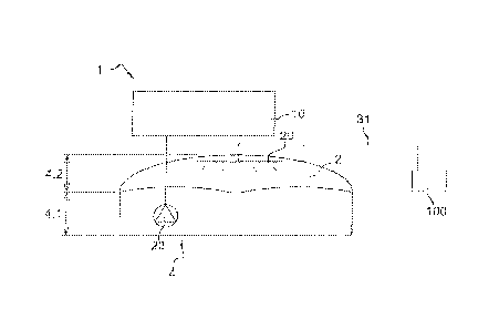
As shown in figure 1, the facility 1 according to a first embodiment
comprises a tank 4 comprising a lower region 4.1 intended to contain liquefied
gas 2 in
the liquid state and an upper region 4.2 intended to contain the vapors of the
liquefied
gas 2. Furthermore, the facility 1 comprises a cooling circuit 10,
particularly shown in
figure 2. Preferably, the cooling circuit 10 is located outside the tank, i.e.
the liquefied
gas is (only) cooled outside the tank. In other words, the liquefied gas is
taken from the
tank, is cooled outside the tank and is then reinjected into the tank in the
cooled state.
The cooling device 10 is connected to the fluid inside the tank 4 via a
sampling pipe that
penetrates the tank. The tank 4 is equipped with a pump 22 that allows the
liquefied
CA 03035849 2019-03-05
2015 P00474_EDC/FG
9
gas in the liquid state to be brought to the cooling circuit in order to be
cooled and with
at least one injection component 20 that allows the cooled liquefied gas to be
reinjected
into the tank 4. The injection component comprises a return pipe that connects
the
cooling device (outside the tank) to the inside of the tank 4 and comprises
the injection
component 20. Advantageously, the injection component 20 can comprise a
plurality
of nozzles.
Furthermore, and as shown in figure 1 according to a first embodiment of
the facility, the facility 1 comprises a connection line 31 configured to
route gas to be
liquefied from at least one remote container 100, which is separate and
independent
from the facility 1, to the tank of the facility.
According to a variation of the first embodiment shown in figure 3, the
facility 1 comprises an injection pipe 30 fluidly connecting the cooling
circuit and the
injection component 20, and at least one bypass pipe 32 connected to the
injection pipe
30 and intended to transfer some of the cooled liquefied gas 2 to a remote
container
(not shown), which is separate and independent from the facility 1.
For example, another tank 4 is shown as a dotted line in figure 3. This tank
4, of the same facility or of another facility, can be supplied with liquefied
gas via the
bypass pipe 32 and a respective injection component 20, where applicable.
Of course, in another variation (not shown), the bypass pipe 32 and the
connection line 31 can be installed on the same facility.
As shown in figure 2, and irrespective of the configuration of the facility 1,
the cooling circuit 10 is closed and autonomous and is configured to be
supplied with
liquefied gas 2 in the liquid state coming from the tank 4. The cooling
circuit 10
comprises at least one compressor 12 configured to compress a cycle gas 3, at
least one
engine 14, at least one turbine 18, and at least one first heat exchanger 16
configured
to generate a heat exchange between the liquefied gas 2 and the cycle gas.
As can be seen in figure 2, the engine 14 is mechanically connected, on the
one hand, to the compressor 12 in order to drive the compressor 12 and, on the
other
hand, to the turbine 18 so that the turbine 18 drives the engine 14.
The cooling circuit 10 further comprises a second heat exchanger 24
configured to generate a heat exchange between the compressed cycle gas 3 and
the
expanded cycle gas 3, as shown in figure 2.
The cooling circuit 10 further comprises a third heat exchanger 26
configured to generate a heat exchange between the compressed cycle gas 3 and
water
or air or any other coolant coming from an external source.
CA 03035849 2019-03-05
2015P00474_EDC/FG
In the event that one or more of the tank(s) 4 contain(s) liquefied natural
gas on a vehicle, in particular a ship, the natural gas that vaporizes can be
used as fuel
for an engine of the vehicle and any excess gas is burnt in a flare, for
example.
Figure 4A shows the distribution of the consumption (axis of ordinates yin
tons per day) of the natural gas vaporized on a ship over time (axis of
abscissae x)
toward the engine (C: section with horizontal shading), toward the flare (A:
section with
inclined shading) and toward the reliquefaction system (B: section without
shading) for
a known facility.
Figure 4B shows the distribution of the consumption in tons per day (y
axis) of the natural gas vaporized on a ship over time (x axis) toward the
engine (C),
toward the flare (A) and toward the reliquefaction system (B) for the facility
according
to the invention.
It can be seen that, according to the known facility (figure 4A), losses of
vaporized gas remain at the end of the journey since the engines and the
facility are not
designed to recover this gas. However, in figure 4B, by virtue of the facility
according
to the invention, there is no longer a peak at the end of the journey, the
losses are
minimal, particularly by virtue of the system for refrigerating the tanks.
Of course, the invention is not limited to the embodiments described and
shown in the accompanying figures. Modifications are still possible,
particularly in
terms of the constitution of the various elements or by substitution of
equivalent
techniques, yet without departing from the scope of protection of the
invention.