Note: Descriptions are shown in the official language in which they were submitted.
CA 03036073 2019-03-06
CA Application
Blakes Ref: 60233/00032
- 1 ¨
GASKET AND METHOD FOR MANUFACTURING SAME
Technical Field
[0001] The present invention relates to a gasket that includes seal parts on
both
sides of the gasket in a thickness direction and a method for manufacturing
the
same. For example, the gasket according to the present invention is used as a
gasket for a fuel cell or is used as other general gaskets.
Background Art
[0002] Conventionally, a rubber-only type gasket 101 as illustrated in FIG. 11
and
a separator-integrated gasket 111 in which a gasket body 113 is integrally
molded
with a separator 112 as illustrated in FIG. 12 have been known as a gasket
used
for a fuel cell.
Prior Art Document
Patent Document
[0003] Patent Document 1: Japanese Unexamined Patent Publication No. 2015-
106477
Patent Document 2: Japanese Unexamined Patent Publication No. 2016-
95961
Summary of Invention
Problem to be Solved by the Invention
[0004] However, because the rubber-only type gasket 101 is configured of only
rubber material, this gasket is too flexible and thus has trouble in handling
such as
carrying.
[0005] Moreover, the separator-integrated gasket 111 needs to previously apply
an adhesive 114 on the separator 112 and then integrally mold the gasket body
23594612.1
CA 03036073 2019-03-06
CA Application
Blakes Ref: 60233/00032
-2-
113 therewith or to mold the gasket body 113 from a self-adhesive material.
Therefore, there is a disadvantage that man-hours increase because an adhesive
applying process is performed, and also there is a disadvantage that the
option for
rubber material is limited to material with self-adhesiveness.
[0006] In view of the above points, an object of the present invention is to
provide
a gasket and a method for manufacturing the same, which can improve handling
as compared to the rubber-only type gasket.
Means for Solving the Problem
[0007] To solve the above problems, a gasket according to the present
invention
includes a reinforcing body that is made of a resin film, a one-side gasket
body that
is provided on one surface of the reinforcing body in a thickness direction
thereof,
and another-side gasket body that is provided on another surface of the
reinforcing
body in the thickness direction, wherein the reinforcing body has, in a
portion
sandwiched between both the gasket bodies, a three-dimensional shape in which
the resin film is bent in its thickness direction.
[0008] Moreover, in the gasket described above, the one-side gasket body
includes an inversely-tapered engaging convex portion that protrudes toward
the
other-side gasket body, the reinforcing body includes a deformation portion as
the
three-dimensional shape that is deformed along a shape of the engaging convex
portion, and the other-side gasket body includes an inversely-tapered engaging
concave portion that embeds therein the engaging convex portion and the
deformation portion.
[0009] Moreover, a method, for manufacturing the gasket described above,
includes: sequentially performing a process of molding the one-side gasket
body
on the one surface of the reinforcing body in the thickness direction by using
a first
metal mold and a process of molding the other-side gasket body on the other
surface of the reinforcing body in the thickness direction by using a second
metal
23594612,1
CA 03036073 2019-03-06
CA Application
Blakes Ref. 60233/00032
- 3 ¨
mold, wherein the first metal mold includes a first split mold and a second
split mold
and includes a structure sandwiching the reinforcing body between both the
split
molds, the first split mold includes a one-side gasket-body molding cavity to
mold
a portion other than the engaging convex portion within the one-side gasket
body,
and the second split mold includes an engaging-convex-portion molding cavity
to
mold the engaging convex portion within the one-side gasket body, the second
metal mold includes a first split mold and a second split mold and includes a
structure sandwiching the reinforcing body between both the split molds, the
first
split mold of the second metal mold includes an accommodating space to
accommodate the portion other than the engaging convex portion within the one-
side gasket body, and the second split mold of the second metal mold includes
another-side gasket-body molding cavity to accommodate the engaging convex
portion within the one-side gasket body and the deformation portion covering
the
engaging convex portion and to mold the other-side gasket body in a state
where
the portions are accommodated, and the deformation portion is formed by
deforming the reinforcing body along an inner surface of the engaging-convex-
portion molding cavity by using a molding pressure when molding the one-side
gasket body by using the first metal mold.
[0010] Moreover, in the gasket described above, at least one gasket body of
the
one-side gasket body and the other-side gasket body includes a flat surface-
shaped seal surface, and the reinforcing body has a convex shape as the three-
dimensional shape that protrudes toward the flat surface-shaped seal surface.
[0011] Moreover, in the gasket described above, the reinforcing body has a
bellows shape, and one of a peak and a valley in the bellows shape is defined
as
the convex shape.
[0012] Moreover, a method, for manufacturing the gasket described above,
includes: sequentially performing a process of molding the one-side gasket
body
on the one surface of the reinforcing body in the thickness direction by using
a first
23594612.1
CA 03036073 2019-03-06
CA Application
Blakes Ref. 60233/00032
- 4 ¨
metal mold and a process of molding the other-side gasket body on the other
surface of the reinforcing body in the thickness direction by using a second
metal
mold, wherein the first metal mold includes a first split mold and a second
split mold
and includes a structure sandwiching the reinforcing body between both the
split
molds, the first split mold includes a one-side gasket-body molding cavity to
mold
the one-side gasket body, and the second split mold includes a concave portion
to
form the convex shape on the reinforcing body, the second metal mold includes
a
first split mold and a second split mold and includes a structure sandwiching
the
reinforcing body between both the split molds, the first split mold of the
second
metal mold includes an accommodating space to accommodate the one-side
gasket body, and the second split mold of the second metal mold includes
another-
side gasket-body molding cavity to accommodate the convex shape and to mold
the other-side gasket body in a state where the convex shape is accommodated,
and the convex shape is formed by deforming the reinforcing body along an
inner
surface of the concave portion by using a molding pressure when molding the
one-
side gasket body by using the first metal mold.
[0013] Furthermore, a method, for manufacturing the gasket described above,
includes: sequentially performing a process of molding the one-side gasket
body
on the one surface of the reinforcing body in the thickness direction by using
a first
metal mold and a process of molding the other-side gasket body on the other
surface of the reinforcing body in the thickness direction by using a second
metal
mold, wherein the first metal mold includes a first split mold and a second
split mold
and includes a structure sandwiching the reinforcing body between both the
split
molds, the first split mold includes a one-side gasket-body molding cavity to
mold
the one-side gasket body, and the second split mold includes an uneven portion
to
form the bellows shape on the reinforcing body, the second metal mold includes
a
first split mold and a second split mold and includes a structure sandwiching
the
reinforcing body between both the split molds, the first split mold of the
second
23594612.1
CA 03036073 2019-03-06
CA Application
Blakes Ref: 60233/00032
- 5 ¨
metal mold includes an accommodating space to accommodate the one-side
gasket body, and the second split mold of the second metal mold includes
another-
side gasket-body molding cavity to accommodate the bellows shape and to mold
the other-side gasket body in a state where the bellows shape is accommodated,
and the bellows shape is formed by deforming the reinforcing body along a
surface
of the uneven portion by using a molding pressure when molding the one-side
gasket body by using the first metal mold.
Effect of the Invention
[0014] In the present invention that employs the above configuration, because
the
one-side gasket body and the other-side gasket body are reinforced by the
reinforcing body made of resin film, strength or shape retention of the gasket
as a
whole is raised compared to when there is not the reinforcing body. Therefore,
it
is possible to improve the handling of the gasket as compared to the rubber-
only
type gasket.
[0015] Moreover, because the reinforcing body has a three-dimensional shape in
which a resin film is bent in its thickness direction in a portion sandwiched
between
both the gasket bodies, the three-dimensional shape can be used for the
joining of
the components and the surface pressure adjustment of the seal parts.
Brief Description of Drawings
[0016] FIG. 1 is a cross-sectional diagram illustrating the main parts of a
gasket
according to a first embodiment of the present invention.
FIGS. 2(A) and 2(B) are diagrams explaining a manufacturing process of
the gasket.
FIG. 3 is a diagram explaining the manufacturing process of the gasket.
FIGS. 4 (A) and 4(B) are diagrams explaining the manufacturing process
of the gasket.
23594612.1
CA 03036073 2019-03-06
CA Application
Blakes Ref: 60233/00032
- 6 ¨
FIG. 5 is a cross-sectional diagram illustrating the main parts of a gasket
according to a second embodiment of the present invention.
FIGS. 6 (A) and 6(B) are diagrams explaining a manufacturing process of
the gasket.
FIGS. 7 (A) and 7(B) are diagrams explaining the manufacturing process
of the gasket.
FIG. 8 is a cross-sectional diagram illustrating the main parts of a gasket
according to a third embodiment of the present invention.
FIGS. 9 (A) and 9(B) are diagrams explaining a manufacturing process of
the gasket.
FIGS. 10 (A) and 10(B) are diagrams explaining the manufacturing
process of the gasket.
FIG. 11 is a cross-sectional diagram illustrating the main parts of a gasket
according to a conventional example.
FIG. 12 is a cross-sectional diagram illustrating the main parts of a gasket
according to another conventional example.
Description of Embodiments
[0017] Next, exemplary embodiments will be explained in accordance with the
accompanying drawings.
[0018] First Embodiment
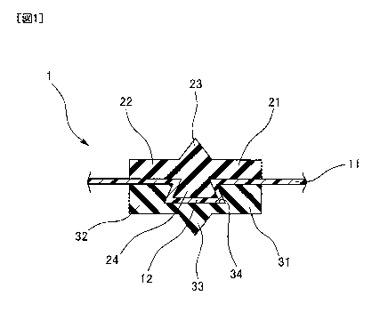
As illustrated in FIG. 1, a gasket indicated by the reference number 1 as a
whole is a double-sided gasket that includes seal parts on both sides in a
thickness
direction thereof, and is configured by a combination of a reinforcing body 11
made
of a resin film having a predetermined thickness, a one-side gasket body 21
provided on one surface (upper surface in the diagram) of the reinforcing body
11
in a thickness direction thereof, and another-side gasket body 31 provided on
another surface (lower surface in the diagram) of the reinforcing body 11 in
the
23594612.1
CA 03036073 2019-03-06
CA Application
Blakes Ref: 60233/00032
- 7 ¨
thickness direction. The one-side gasket body 21 and the other-side gasket
body
31 are arranged with their planar positions aligned and their gasket widths
are set
to be equal or substantially equal. The gasket 1 is used as a gasket for a
fuel cell.
[0019] The one-side gasket body 21 is molded of a predetermined rubber-like
elastic body (may not have self-adhesiveness), and includes a base 22 whose
cross section has a rectangular shape. A seal lip 23 is integrally provided on
the
upper surface of the base 22 and an inversely-tapered engaging convex portion
24 is integrally provided on the lower surface of the base 22 while protruding
toward
the other-side gasket body 31. Herein, the inversely-tapered shape means that
an angle between the lower surface of the base 22 and the side surface of the
engaging convex portion 24 is set to be smaller than a right angle, and both
side
surfaces of the engaging convex portion 24 are inversely tapered. Therefore,
the
cross section of the engaging convex portion 24 has a trapezoidal or
substantially
trapezoidal shape.
[0020] The reinforcing body 11 made of a resin film is planar. A zone in which
the reinforcing body overlaps with the engaging convex portion 24 is deformed
along the cross-sectional shape of the engaging convex portion 24, and
consequently the reinforcing body includes a deformation portion 12 (also
referred
to as covering portion or convex shape) as a three-dimensional shape that
covers
the engaging convex portion 24. Because the thickness of the resin film is
substantially constant, the engaging convex portion 24 maintains an inversely-
tapered shape even if it is coated by the resin film.
[0021] The other-side gasket body 31 is molded of a predetermined rubber-like
elastic body (may not have self-adhesiveness), and includes a base 32 whose
cross section has a rectangular shape. The other-side gasket body further
includes a seal lip 33 that is integrally provided on the lower surface of the
base 32
and an inversely-tapered engaging concave portion 34 that is provided on the
upper surface of the base 32 to embed therein the engaging convex portion 24
and
23594612.1
CA 03036073 2019-03-06
CA Application
Blakes Ref: 60233/00032
- 8 ¨
the deformation portion 12. Herein, the inversely-tapered shape means that an
angle between the bottom surface and the side surface among the inner surfaces
of the engaging concave portion 34 is set to be smaller than a right angle,
and both
side surfaces of the engaging concave portion 34 are inversely tapered.
Therefore, the cross section of the engaging concave portion 34 has a
trapezoidal
or substantially trapezoidal shape, and further the engaging concave portion
34
has such a size that the engaging concave portion can engage with the engaging
convex portion 24 to thus be retained.
[0022] The kind of the resin film for the reinforcing body 11 is not
particularly
limited if it is a film tolerating a molding temperature, including a general-
purpose
film such as polypropylene, polyethylene, and polystyrene, engineering plastic
such as nylon and polyphenylene sulfide, and the like, as specific examples.
It is
preferable that the thickness of the film is around 0.1 to 0.3 mm although the
thickness depends on the wire diameter and the cross-sectional shape of the
gasket. As a specific example, the material of the gasket bodies 21 and 31 can
include silicone rubber, fluorine-contained rubber, EPDM, P18, and the like.
[0023] In the gasket 1 that includes the above configuration, because the one-
side gasket body 21 and the other-side gasket body 31 made of the rubber-like
elastic body are reinforced by the reinforcing body 11 made of the resin film,
strength or shape retention of the gasket 1 as a whole is raised compared to
when
there is not the reinforcing body 11. Therefore, the handling of the gasket 1
can
be improved as compared to the conventional rubber-only type gasket.
[0024] Moreover, in the gasket 1 having the above configuration, a gasket
product
is manufactured by combining the one-side gasket body 21, the other-side
gasket
body 31, and the reinforcing body 11, and this gasket product is assembled to
a
partner component such as a separator as a single gasket product when
assembling a fuel cell stack similarly to the conventional rubber-only type
gasket.
Therefore, because the gasket is not a gasket that is molded integrally with
the
23594612.1
CA 03036073 2019-03-06
CA Application
Blakes Ref: 60233/00032
- 9 ¨
separator like the conventional separator-integrated gasket, the gasket does
not
require adhesive for integral molding and also does not require to be made of
a
self-adhesive material.
[0025] Moreover, in the gasket 1 having the above configuration, by mutually
engaging the inversely-tapered engaging convex portion 24 provided in the one-
side gasket body 21 with the inversely-tapered engaging concave portion 34
provided in the other-side gasket body 31 in the state where the deformation
portion 12 of the reinforcing body 11 is sandwiched therebetween, the one-side
gasket body 21, the other-side gasket body 31, and the reinforcing body 11 are
integrated with each other. Thus, this unification also does not require
adhesive
and the gasket does not require to be made of a self-adhesive material.
Therefore, the one-side gasket body 21 and the other-side gasket body 31 can
be
fixed to the reinforcing body 11 even if neither the adhesive nor the self-
adhesive
material is used, and the gasket 1 can be manufactured by the combination of
the
one-side gasket body 21, the other-side gasket body 31, and the reinforcing
body
11. The cross-sectional shape of the one-side gasket body 21 and the
other-side
gasket body 31 is not particularly limited. For example, the seal lips 23 and
33
may not be provided.
[0026] Next, a method for manufacturing the gasket 1 having the above
configuration will be explained.
[0027] The manufacturing is performed by an injection molding method. The
injection molding method uses two sets of metal molds consisting of a first
metal
mold and a second metal mold. First, by using the first metal mold, the method
performs a process (first molding process) for molding the one-side gasket
body
21 on one surface of the reinforcing body 11 in the thickness direction. Next,
by
using the second metal mold, the method performs a process (second molding
process) for molding the other-side gasket body 31 on the other surface of the
reinforcing body 11 in the thickness direction.
23594612.1
CA 03036073 2019-03-06
CA Application
Blakes Ref. 60233/00032
- 10 ¨
[0028] First Molding Process
As illustrated in FIG. 2(A), a first metal mold 51 is configured by the
combination of a first split mold (upper mold) 52 and a second split mold
(lower
mold) 53, and a sandwiching structure (sandwiching space) 54 to sandwich the
reinforcing body 11 is provided in the parting portion between both the split
molds
52 and 53. A one-side gasket-body molding cavity 55 to mold a portion (the
base
22 and the seal lip 23) other than the engaging convex portion 24 within the
one-
side gasket body 21 is provided on the parting surface of the first split mold
52.
An engaging-convex-portion molding cavity 56 to mold the engaging convex
portion 24 within the one-side gasket body 21 is provided on the parting
surface of
the second split mold 53. The latter engaging-convex-portion molding cavity 56
also forms an inversely-tapered shape to provide the shape of a reverse taper
to
the engaging convex portion 24.
[0029] As the procedure of the process, mold clamping is performed on the
planar
reinforcing body 11 in the state where the reinforcing body is sandwiched
between
both the split molds 52 and 53 as illustrated in FIG. 2(A), and then a molding
material is filled up into the cavities 55 and 56 from a gate not illustrated
to mold
the one-side gasket body 21 as illustrated in FIG. 2(B). At this time, the
portion
of the reinforcing body 11 is deformed along the inner surface of the engaging-
convex-portion molding cavity 56 due to its molding pressure (injection
pressure),
and thus the molding material is filled up into not only the one-side gasket-
body
molding cavity 55 but also the engaging-convex-portion molding cavity 56. As a
result, the engaging convex portion 24 is molded in the one-side gasket body
21
and the deformation portion 12 is formed in the reinforcing body 11.
[0030] Moreover, the adhesive is not used in this molding, but when the one-
side
gasket body 21 has an adherence property on its material, the one-side gasket
body 21 is regarded to adhere to the reinforcing body 11 due to the adherence
property.
23594612.1
CA 03036073 2019-03-06
CA Application
Blakes Ref: 60233/00032
- 11 ¨
[0031] Next, as illustrated in FIG. 3, mold opening is performed to detach
(release)
a molding product (the one-side gasket body 21 and the reinforcing body 11)
attached to the second split mold 53 from the second split mold 53.
[0032] When this mold opening is performed, it is concerned that the one-side
gasket body 21 and the reinforcing body 11 are separated from each other by
causing the one-side gasket body 21 to adhere to the first metal mold 51 and
the
reinforcing body 11 to be left on the second split mold 53. As described
above, in
the embodiment of the present invention, because the inversely-tapered
engaging
convex portion 24 engages with the engaging-convex-portion molding cavity 56
having the same inversely-tapered shape so as to be retained, the one-side
gasket
body 21 and the reinforcing body 11 are not separated.
Therefore, the
subsequent process is smoothly continued. The angle of the reverse taper is
sufficient if it is not less than 0.1 .
[0033] Second Molding Process
As illustrated in FIG. 4(A), a second metal mold 61 is configured by a
combination of a first split mold (lower mold) 62 and a second split mold
(upper
mold) 63, and a sandwiching structure 64 to sandwich the reinforcing body 11
is
provided in the parting portion between both the split molds 62 and 63. An
accommodating space 65 to accommodate a portion (the base 22 and the seal lip
23) other than the engaging convex portion 24 within the one-side gasket body
21
that is already molded in the first molding process is provided on the parting
surface
of the first split mold 62. Another-side gasket-body molding cavity 66 to
accommodate the engaging convex portion 24 within the one-side gasket body 21
and the deformation portion 12 covering the engaging convex portion 24 and to
mold the other-side gasket body 31 in the state where these are accommodated
is
provided on the parting surface of the second split mold 63.
[0034] As the procedure of the process, mold clamping is performed in the
state
where the reinforcing body 11 is sandwiched between both the split molds 62
and
23594612.1
CA 03036073 2019-03-06
CA Application
Blakes Ref: 60233/00032
- 12 ¨
63 and a portion other than the engaging convex portion 24 within the one-side
gasket body 21 is accommodated in the accommodating space 65 as illustrated in
FIG. 4(A), and a molding material is filled up into the other-side gasket-body
molding cavity 66 from a gate not illustrated to mold the other-side gasket
body 31
as illustrated in FIG. 4(B). At this time, because the engaging convex portion
24
within the one-side gasket body 21 and the deformation portion 12 covering the
engaging convex portion 24 are accommodated in the other-side gasket-body
molding cavity 66, the engaging concave portion 34 is molded in the other-side
gasket body 31 simultaneously with molding the other-side gasket body 31.
[0035] Moreover, the adhesive is not used even in this molding, but when the
other-side gasket body 31 has an adherence property on its material, the other-
side gasket body 31 is regarded to adhere to the reinforcing body 11 due to
this
adherence property.
[0036] Next, mold opening is performed to detach (release) the gasket 1 formed
by the combination of the reinforcing body 11, the one-side gasket body 21,
and
the other-side gasket body 31 from the second metal mold 61.
[0037] The molded gasket 1 is regarded as an integrated product that does not
use adhesive by causing the inversely-tapered engaging convex portion 24
provided in the one-side gasket body 21 and the inversely-tapered engaging
concave portion 34 provided in the other-side gasket body 31 to engage with
each
other in the state where the deformation portion 12 of the reinforcing body 11
is
sandwiched therebetween.
[0038] Second Embodiment
As illustrated in FIG. 5, a gasket indicated by the reference number 1 as
a whole is a double-sided gasket that includes seal parts on both sides in a
thickness direction thereof, and is configured by a combination of: the
reinforcing
body 11 made of a resin film having a predetermined thickness; the one-side
gasket body 21 provided on one surface (upper surface in the diagram) of the
23594612.1
CA 03036073 2019-03-06
CA Application
Blakes Ref. 60233/00032
- 13 ¨
reinforcing body 11 in the thickness direction; and the other-side gasket body
31
provided on another surface (lower surface in the diagram) of the reinforcing
body
11 in the thickness direction. The one-side gasket body 21 and the other-side
gasket body 31 are arranged with their planar positions aligned and their
gasket
widths are set to be equal or substantially equal. The gasket 1 is used as a
gasket
for a fuel cell.
[0039] The one-side gasket body 21 is molded of a predetermined rubber-like
elastic body (may not have self-adhesiveness), and includes the base 22 whose
cross section has a rectangular shape. A seal surface 25 having the seal lip
23
is provided on the upper surface of the base 22.
[0040] The other-side gasket body 31 is molded of a predetermined rubber-like
elastic body (may not have self-adhesiveness), and includes the base 32 whose
cross section has a rectangular shape. A flat surface-shaped seal surface 35
that
does not have a seal lip is provided on the lower surface of the base 32.
[0041] The reinforcing body 11 made of the resin film is planar. A sectional
arc-
like convex shape 13 as a three-dimensional shape that protrudes toward the
flat
surface-shaped seal surface 35 of the other-side gasket body 31 is provided in
a
portion of a region sandwiched by both the gasket bodies 21 and 31. Only the
portion has a three-dimensional shape.
[0042] The kind of the resin film for the reinforcing body 11 is not
particularly
limited if it is a film tolerating a molding temperature, but can include a
general-
purpose film such as polypropylene, polyethylene, and polystyrene, engineering
plastic such as nylon and polyphenylene sulfide, and the like, as specific
examples.
It is preferable that the thickness of the film is around 0.1 to 0.3 mm
although the
thickness depends on the wire diameter and the cross-sectional shape of the
gasket. As a specific example, the material of the gasket bodies 21 and 31 can
include silicone rubber, fluorine-contained rubber, EPDM, PIB, and the like.
[0043] In the gasket 1 that includes the above configuration, because the one-
23594612.1
CA 03036073 2019-03-06
CA Application
Blakes Ref: 60233/00032
- 14 ¨
side gasket body 21 and the other-side gasket body 31 made of the rubber-like
elastic body are reinforced by the reinforcing body 11 made of the resin film,
strength or shape retention of the gasket 1 as a whole is raised compared to
when
there is not the reinforcing body 11. Therefore, the handling of the gasket 1
can
be improved as compared to the conventional rubber-only type gasket.
[0044] Moreover, in the gasket 1 having the above configuration, a gasket
product is manufactured by combining the one-side gasket body 21, the other-
side
gasket body 31, and the reinforcing body 11, and this gasket product is
assembled
to a partner component such as a separator as a single gasket product when
assembling a fuel cell stack similarly to the conventional rubber-only type
gasket.
Therefore, because the gasket is not a gasket that is molded integrally with
the
separator like the conventional separator-integrated gasket, the gasket does
not
require adhesive for integral molding and also the gasket does not require to
be
made of a self-adhesive material.
[0045] Moreover, in the gasket 1 having the above configuration, because the
reinforcing body 11 made of the resin film has the convex shape 13 that
protrudes
toward the flat surface-shaped seal surface 35 of the other-side gasket body
31, a
seal surface pressure rises on the flat surface-shaped seal surface 35 and the
peak
value of the seal surface pressure rises by using the convex shape 13 as a
backup
part. Therefore, the seal surface pressure on the flat surface-shaped seal
surface
35 can be increased to improve sealability compared to when there is not the
convex shape.
[0046] Next, a method for manufacturing the gasket 1 having the above
configuration will be explained.
[0047] The manufacturing is performed by an injection molding method. The
injection molding method uses two sets of metal molds consisting of a first
metal
mold and a second metal mold. First, the method performs a process (first
molding process) for molding the one-side gasket body 21 on one surface of the
23594612.1
CA 03036073 2019-03-06
CA Application
Blakes Ref: 60233/00032
- 15 ¨
reinforcing body 11 in the thickness direction by using the first metal mold.
Next,
the method performs a process (second molding process) for molding the other-
side gasket body 31 on the other surface of the reinforcing body 11 in the
thickness
direction by using the second metal mold.
[0048] First Molding Process
As illustrated in FIG. 6(A), the first metal mold 51 is configured by a
combination of the first split mold (upper mold) 52 and the second split mold
(lower
mold) 53, and the sandwiching structure (sandwiching space) 54 to sandwich the
reinforcing body 11 is provided in the parting portion between both the split
molds
52 and 53. The one-side gasket-body molding cavity 55 to mold the one-side
gasket body 21 is provided on the parting surface of the first split mold 52,
and a
concave portion 57 to form the convex shape 13 of the reinforcing body 11 is
provided on the parting surface of the second split mold 53.
[0049] As the procedure of the process, mold clamping is performed in the
state
where the planar reinforcing body 11 is sandwiched between both the split
molds
52 and 53 as illustrated in FIG. 6(A), and a molding material is filled up
into the
cavity 55 from a gate 58 to mold the one-side gasket body 21 as illustrated in
FIG.
6(B). At this time, the portion of the reinforcing body 11 is deformed along
the
inner surface of the concave portion 57 due to its molding pressure (injection
pressure) to form the convex shape 13.
[0050] Moreover, because the adhesive is not used in this molding and the one-
side gasket body 21 has an adherence property on its material, the one-side
gasket
body 21 is regarded to adhere to the reinforcing body 11 due to the adherence
property.
[0051] Next, mold opening is performed to detach (release) a molding product
(the one-side gasket body 21 and the reinforcing body 11) attached to the
second
split mold 53 from the second split mold 53.
[0052] Second Molding Process
23594612.1
CA 03036073 2019-03-06
CA Application
Blakes Ref: 60233/00032
- 16 ¨
As illustrated in FIG. 7(A), the second metal mold 61 is configured by a
combination of the first split mold (lower mold) 62 and the second split mold
(upper
mold) 63, and the sandwiching structure 64 to sandwich the reinforcing body 11
is
provided in the parting portion between both the split molds 62 and 63. The
accommodating space 65 to accommodate the one-side gasket body 21 that is
already molded in the first molding process is provided on the parting surface
of
the first split mold 62, and the other-side gasket-body molding cavity 66 to
accommodate the convex shape 13 of the reinforcing body 11 and to mold the
other-side gasket body 31 in the state where the convex shape is accommodated
is provided on the parting surface of the second split mold 63.
[0053] As the procedure of the process, mold clamping is performed in the
state
where the reinforcing body 11 is sandwiched between both the split molds 62
and
63 and the one-side gasket body 21 is accommodated in the accommodating
space 65 as illustrated in FIG. 7(A), and a molding material is filled up into
the
other-side gasket-body molding cavity 66 from a gate 67 to mold the other-side
gasket body 31 as illustrated in FIG. 7(B). At this time, because the convex
shape
13 of the reinforcing body 11 is accommodated in the other-side gasket-body
molding cavity 66, the convex shape 13 is embedded by the other-side gasket
body
31 simultaneously with molding the other-side gasket body 31.
[0054] Moreover, because the adhesive is not used even in this molding and the
other-side gasket body 31 has an adherence property on its material, the other-
side gasket body 31 is regarded to adhere to the reinforcing body 11 due to
the
adherence property.
[0055] Next, mold opening is performed to detach (release) the gasket 1 formed
by the combination of the reinforcing body 11, the one-side gasket body 21,
and
the other-side gasket body 31 from the second metal mold 61.
[0056] Because the one-side gasket body 21 and the other-side gasket body 31
adhere to the reinforcing body 11, the molded gasket 1 is regarded as an
integrated
23594612.1
CA 03036073 2019-03-06
CA Application
Blakes Ref: 60233/00032
- 17 ¨
product that is molded without using adhesive. Moreover, any of the one-side
gasket body 21 and the other-side gasket body 31 may adhere to the reinforcing
body 11 by using the adhesive if needed.
[0057] Third Embodiment
As illustrated in FIG. 8, a double-sided gasket indicated by the reference
number 1 as a whole is configured by a combination of: the reinforcing body 11
made of a resin film having a predetermined thickness; the one-side gasket
body
21 provided on one surface (upper surface in the diagram) of the reinforcing
body
11 in a thickness direction thereof; and the other-side gasket body 31
provided on
another surface (lower surface in the diagram) of the reinforcing body 11 in
the
thickness direction. The one-side gasket body 21 and the other-side gasket
body
31 are arranged with their planar positions aligned and their gasket widths
are set
to be equal or substantially equal. The gasket 1 is used as a gasket for a
fuel cell.
[0058] The one-side gasket body 21 is molded of a predetermined rubber-like
elastic body (may not have self-adhesiveness), and includes the base 22 whose
cross section has a rectangular shape. The flat surface-shaped seal surface 25
that does not have a seal lip is provided on the upper surface of the base 22.
[0059] The other-side gasket body 31 is molded of a predetermined rubber-like
elastic body (may not have self-adhesiveness), and includes the base 32 whose
cross section has a rectangular shape. The flat surface-shaped seal surface 35
that does not have a seal lip is provided on the lower surface of the base 32.
[0060] The reinforcing body 11 made of the resin film is planar. A bellows
shape
14 as a three-dimensional shape is provided in a portion of a region
sandwiched
by both the gasket bodies 21 and 31 so that only the portion has a three-
dimensional shape. Herein, peaks 15 within the bellows shape 14 have a convex
shape protruding toward the flat surface-shaped seal surface 25 provided in
the
one-side gasket body 21, and valleys 16 within the bellows shape 14 have a
convex shape protruding toward the flat surface-shaped seal surface 35
provided
23594612.1
CA 03036073 2019-03-06
CA Application
Blakes Ref: 60233/00032
- 18 ¨
in the other-side gasket body 31. The number of each of the peaks 15 and the
valleys 16 is two or more (in the diagram, the peaks 15 are provided at three
places
and the valleys 16 are provided at four places).
[0061] The kind of the resin film for the reinforcing body 11 is not
particularly
limited if it is a film tolerating a molding temperature, including a general-
purpose
film such as polypropylene, polyethylene, and polystyrene, engineering plastic
such as nylon and polyphenylene sulfide, and the like, as specific examples.
It is
preferable that the thickness of the film is around 0.1 to 0.3 mm although the
thickness depends on the wire diameter and the cross-sectional shape of the
gasket. As a specific example, the material of the gasket bodies 21 and 31 can
include silicone rubber, fluorine-contained rubber, EPDM, PIB, and the like.
[0062] In the gasket 1 that includes the above configuration, because the one-
side gasket body 21 and the other-side gasket body 31 made of the rubber-like
elastic body are reinforced by the reinforcing body 11 made of the resin film,
strength or shape retention of the gasket 1 as a whole is raised compared to
when
there is not the reinforcing body 11. Therefore, the handling of the gasket 1
can
be improved as compared to the conventional rubber-only type gasket.
[0063] Moreover, in the gasket 1 having the above configuration, a gasket
product is manufactured by combining the one-side gasket body 21, the other-
side
gasket body 31, and the reinforcing body 11, and this gasket product is
assembled
to a partner component such as a separator as a single gasket product when
assembling a fuel cell stack similarly to the conventional rubber-only type
gasket.
Therefore, because the gasket is not a gasket that is molded integrally with
the
separator like the conventional separator-integrated gasket, the gasket does
not
require adhesive for integral molding and also the gasket does not require to
be
made of a self-adhesiveness material.
[0064] Moreover, in the gasket 1 having the above configuration, the bellows
shape 14 is provided in the reinforcing body 11 made of the resin film.
Herein, the
23594612.1
CA 03036073 2019-03-06
CA Application
Blakes Ref: 60233/00032
- 19 ¨
peaks 15 within the bellows shape 14 have a convex shape protruding toward the
flat surface-shaped seal surface 25 provided in the one-side gasket body 21
and
the valleys 16 within the bellows shape 14 have a convex shape protruding
toward
the flat surface-shaped seal surface 35 provided in the other-side gasket body
31.
Thus, seal surface pressures respectively rise on the flat surface-shaped seal
surfaces 25 and 35 and the peak values of the seal surface pressures rise by
using
these convex shapes as a backup part. Therefore, the seal surface pressures on
the flat surface-shaped seal surfaces 25 and 35 can be increased to improve
sealability compared to when there is not the convex shape.
[0065] Next, a method for manufacturing the gasket 1 having the above
configuration will be explained.
[0066] The manufacturing is performed by an injection molding method. The
injection molding method uses two sets of metal molds made of a first metal
mold
and a second metal mold. First, the method performs a process (first molding
process) for molding the one-side gasket body 21 on one surface of the
reinforcing
body 11 in the thickness direction by using the first metal mold. Next, the
method
performs a process (second molding process) for molding the other-side gasket
body 31 on the other surface of the reinforcing body 11 in the thickness
direction
by using the second metal mold.
[0067] First Molding Process
As illustrated in FIG. 9(A), the first metal mold 51 is configured by a
combination of the first split mold (upper mold) 52 and the second split mold
(lower
mold) 53, and the sandwiching structure (sandwiching space) 54 to sandwich the
reinforcing body 11 is provided in the parting portion between both the split
molds
52 and 53. The one-side gasket-body molding cavity 55 to mold the one-side
gasket body 21 is provided on the parting surface of the first split mold 52,
and an
uneven portion 59 to form the bellows shape 14 of the reinforcing body 11 is
provided on the parting surface of the second split mold 53.
23594612.1
CA 03036073 2019-03-06
CA Application
Blakes Ref: 60233/00032
- 20 ¨
[0068] As the procedure of the process, mold clamping is performed in the
state
where the planar reinforcing body 11 is sandwiched between both the split
molds
52 and 53 as illustrated in FIG. 9(A), and a molding material is fill up into
the cavity
55 from a gate not illustrated to mold the one-side gasket body 21 as
illustrated in
FIG. 9(B). At this time, the portion of the reinforcing body 11 is deformed
along
the surface of the uneven portion 59 to form the bellows shape 14 due to its
molding
pressure (injection pressure).
[0069] Moreover, because the adhesive is not used in this molding and the one-
side gasket body 21 has an adherence property on its material, the one-side
gasket
body 21 is regarded to adhere to the reinforcing body 11 due to this adherence
property.
[0070] Next, mold opening is performed to detach (release) a molding product
(the one-side gasket body 21 and the reinforcing body 11) attached to the
second
split mold 53 from the second split mold 53.
[0071] Second Molding Process
As illustrated in FIG. 9(A), the second metal mold 61 is configured by a
combination of the first split mold (lower mold) 62 and the second split mold
(upper
mold) 63, and the sandwiching structure 64 to sandwich the reinforcing body 11
is
provided in the parting portion between both the split molds 62 and 63. The
accommodating space 65 to accommodate the one-side gasket body 21 that is
already molded in the first molding process is provided on the parting surface
of
the first split mold 62. The other-side gasket-body molding cavity 66 to
accommodate the bellows shape 14 of the reinforcing body 11 and to mold the
other-side gasket body 31 in the state where the bellows shape is accommodated
is provided on the parting surface of the second split mold 63.
[0072] As the procedure of the process, mold clamping is performed in the
state
where the reinforcing body 11 is sandwiched between both the split molds 62
and
63 and the one-side gasket body 21 is accommodated in the accommodating
23594612.1
CA 03036073 2019-03-06
CA Application
Blakes Ref: 60233/00032
- 21 ¨
space 65 as illustrated in FIG. 9(A), and a molding material is filled up into
the
other-side gasket-body molding cavity 66 from a gate not illustrated to mold
the
other-side gasket body 31 as illustrated in FIG. 9(B). At this time, because
the
bellows shape 14 of the reinforcing body 11 is accommodated in the other-side
gasket-body molding cavity 66, the bellows shape 14 is embedded by the other-
side gasket body 31 simultaneously with molding the other-side gasket body 31.
[0073] Moreover, because the adhesive is not used even in this molding and the
other-side gasket body 31 has an adherence property on its material, the other-
side gasket body 31 is regarded to adhere to the reinforcing body 11 due to
this
adherence property.
[0074] Next, mold opening is performed to detach (release) the gasket 1 formed
by the combination of the reinforcing body 11, the one-side gasket body 21,
and
the other-side gasket body 31 from the second metal mold 61.
[0075] Because the one-side gasket body 21 and the other-side gasket body 31
adhere to the reinforcing body 11, the molded gasket 1 is regarded as an
integrated
product that is molded without using adhesive. Moreover, any of the one-side
gasket body 21 and the other-side gasket body 31 may adhere to the reinforcing
body 11 by using the adhesive if needed. Moreover, insert molding may be
performed by preparing and using the reinforcing body 11 in which the bellows
shape 14 is previously formed.
Description of Reference Numerals
[0076] 1 gasket
11 reinforcing body
12 deformation portion
13 convex shape
14 bellows shape
15 peaks
23594612.1
CA 03036073 2019-03-06
CA Application
Blakes Ref: 60233/00032
- 22 ¨
16 valleys
21 one-side gasket body
22, 32 base
23, 33 seal lip
24 engaging convex portion
25, 35 seal surface
31 other-side gasket body
34 engaging concave portion
51 first metal mold
52 first split mold (upper mold)
53 second split mold (lower mold)
54, 64 sandwiching structure
55 one-side gasket-body molding cavity
56 engaging-convex-portion molding cavity
57 concave portion
58, 67 gate
59 uneven portion
61 second metal mold
62 first split mold (lower mold)
63 second split mold (upper mold)
65 accommodating space
66 other-side gasket-body molding cavity
23594612.1