Note: Descriptions are shown in the official language in which they were submitted.
CA 03036344 2019-03-08
SPECIFICATION
TITLE OF INVENTION: REFRIGERATION SYSTEM AND CONTROL DEVICE
Cross Reference To Related Applications
[0001]
This application is based on Japanese Patent Application No.
2016-182461 filed on September 19, 2016, the disclosure of which is
incorporated
herein by reference.
Technical Field
[0002]
The present disclosure relates to a refrigeration system applied to a
moving object and a control device for the refrigeration system.
Background Art
[0003]
Conventionally, as a refrigeration system applied to a moving object, there
has been known a trailer refrigeration device which cools an storage space of
a
trailer of a refrigeration vehicle (for example, refer to Patent Literature
1). The
trailer refrigeration apparatus disclosed in Patent Literature 1 has a
configuration
in which an air cooled by a refrigerator is supplied to a storage space. The
refrigerator is configured to be driven by an electric power from a generator
driven
by a power generation engine.
Prior Art Literatures
Patent Literature
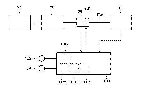
[0004]
Patent Literature 1: JP 2011-11643 A
Summary of Invention
[0005]
1 / 25
CA 03036344 2019-03-08
In the refrigeration system described above, a constant speed diesel
engine which is maintained at a predetermined rotation speed is generally
employed as a power generation engine. If the power generation engine is
provided by the constant speed engine, the power generation engine operates at
a high rotation speed even when a load of the refrigerator is small. This is
not
preferable because the above configuration causes an energy efficiency of the
entire system to deteriorate.
[0006]
On the other hand, it is conceivable to improve the energy efficiency of the
entire system by configuring the power generation engine so as to be able to
change the rotation speed in accordance with the load of the refrigerator.
[0007]
However, when the power generation engine is configured to be capable
of changing the rotation speed in accordance with the load of the
refrigerator,
there is a need to add a configuration for changing the rotation speed to the
power
generation engine, and there is a conflict that the system configuration
becomes
remarkably complicated.
[0008]
It is an object of the present disclosure to provide a refrigeration system
capable of improving an energy efficiency of an entire system while reducing
complexity of a system configuration, and a control device for the
refrigeration
system.
[0009]
According to one aspect of the present disclosure, a refrigeration system
includes
a generator,
a power generation engine that drives the generator,
a refrigerator that adjusts a temperature of a cooling target space,
an electric power converter that converts an electric power generated by
the generator into a drive output for the refrigerator and supplies the drive
output
to the refrigerator,
an output control unit that controls the drive output from the electric power
2 / 25
CA 03036344 2019-03-08
converter to the refrigerator to adjust an operation state of the
refrigerator,
a characteristic estimation unit that estimates a refrigerator characteristic
of the refrigerator according to an outside air temperature and a temperature
of
the cooling target space, and
an output calculation unit that calculates the drive output as a target drive
output that optimizes an energy efficiency of the entire system based on the
refrigerator characteristic estimated by the characteristic estimation unit, a
preset
engine characteristic of the power generation engine, and a preset generator
characteristic of the generator. Further, the output control unit controls the
drive
output to approach the target drive output calculated by the output
calculation unit.
[0010]
In this manner, since the refrigerator is operated such that the drive output
at which the energy efficiency of the entire system is optimized is set as the
target
drive output, the energy efficiency of the entire system can be optimized
without
adding means for changing the rotation speed of the power generation engine.
In
other words, in the refrigeration system according to the present disclosure,
the
energy efficiency of the entire system can be improved while reducing the
complexity of the system configuration.
[0011]
According to another aspect of the present disclosure, a control device is
provided for a refrigeration system that includes a generator, a power
generation
engine that drives the generator, a refrigerator that adjusts a temperature of
a
cooling target space, and an electric power converter that converts an
electric
power generated by the generator into a drive output for the refrigerator.
[0012]
The control device includes
an output control unit that controls the drive output from the electric power
converter to the refrigerator to adjust an operation state of the
refrigerator,
a characteristic estimation unit that estimates a refrigerator characteristic
of the refrigerator according to an outside air temperature and a temperature
of
the cooling target space, and
an output calculation unit that calculates the drive output as a target drive
3 / 25
CA 03036344 2019-03-08
output that optimizes an energy efficiency of the entire system based on the
refrigerator characteristic estimated by the characteristic estimation unit, a
preset
engine characteristic of the power generation engine, and a preset generator
characteristic of the generator.
[0013]
The output control unit controls the drive output to approach the target
drive output calculated by the output calculation unit.
[0014]
According to the above configuration, the energy efficiency of the entire
system can be optimized without adding means for changing the rotation speed
of
the power generation engine, and therefore the energy efficiency of the entire
system can be improved while reducing the complexity of the system
configuration.
Brief Description of Drawings
[0015]
FIG. 1 is a schematic configuration diagram of a refrigeration vehicle
equipped with a refrigeration system according to a first embodiment.
FIG. 2 is a schematic configuration diagram of a refrigeration system
according to the first embodiment.
FIG. 3 is a block diagram of a refrigeration system according to the first
embodiment.
FIG. 4 is a characteristic diagram showing refrigerator characteristics
defining a correspondence relationship between a refrigerator load and a
refrigeration efficiency of a refrigerator.
FIG. 5 is a characteristic diagram showing engine characteristics defining
a correspondence relationship between an engine load and a drive efficiency of
a
power generation engine.
FIG. 6 is a characteristic diagram showing generator characteristics
defining a correspondence relationship between a generator load and a power
generation efficiency of a generator.
FIG. 7 is a flowchart showing a flow of control processing to be executed
4 / 25
CA 03036344 2019-03-08
by a control device of the refrigeration system according to the first
embodiment.
FIG. 8 is an illustrative diagram illustrating multiple refrigerator
characteristics set for each of an outside air temperature and a temperature
of a
storage space.
FIG. 9 is an illustrative diagram illustrating a method of calculating a
target
drive output in the refrigeration system according to the first embodiment.
FIG. 10 is a flowchart showing a flow of control processing to be executed
by a control device of a refrigeration system according to a second
embodiment.
FIG. 11 is an illustrative diagram illustrating a method of calculating a
target drive output in the refrigeration system according to the second
embodiment.
DETAILED DESCRIPTION OF THE EMBODIMENTS
[0016]
Hereinafter, embodiments of the present disclosure will be described with
reference to the drawings. In the following embodiments, portions that are the
same as or equivalent to those described in the preceding embodiments are
denoted by the same reference numerals, and a description of those portions
may
be omitted. In addition, when only a part of components is described in the
embodiment, the components described in the preceding embodiment can be
applied to other parts of the components. In the following embodiments, the
embodiments can be partially combined with each other as long as there is
particularly no trouble in combination, even if the combinations are not
specified in
particular.
.. [0017]
(First Embodiment)
The present embodiment will be described with reference to FIGS. 1 to 9.
In the present embodiment, an example in which a refrigeration system 20
according to the present disclosure is applied to a refrigeration vehicle 1
that
transports frozen foods and the like will be described. In the present
embodiment,
the refrigeration vehicle configures a moving object to which the
refrigeration
system 20 is applied.
5 / 25
CA 03036344 2019-03-08
[0018]
As shown in FIG. 1, the refrigeration vehicle 1 includes a tractor 12 and a
trailer 14 in which a cargo such as frozen foods is stored. The tractor 12 is
a
towing vehicle that tows the trailer 14. The tractor 12 incorporates an engine
EG
for vehicle travel.
[0019]
The trailer 14 is formed with a storage space 140 in which a cargo such as
frozen foods is stored. The trailer 14 is provided with an apparatus in which
components of the refrigeration system 20 are unitized at a position facing
the
tractor 12.
[0020]
The refrigeration system 20 includes a refrigerator 22 that adjusts a
temperature of the storage space 140, a power generation engine 24, and a
generator 26 that is driven by the power generation engine 24 and outputs an
electric power to be supplied to the refrigerator 22.
[0021]
As shown in FIG. 2, the refrigerator 22 according to the present
embodiment is provided by a vapor compression type refrigeration cycle 220.
The
refrigeration cycle 220 adjusts a temperature of an air for cooling the
storage
space 140. According to the present embodiment, the storage space 140
configures a cooling target space. In the refrigeration cycle 220, a
compressor 222,
a radiator 224, an expansion valve 226, and an evaporator 228 are connected to
each other through a refrigerant pipe.
[0022]
Among the components of the refrigeration cycle 220, the compressor 222
compresses and discharges a refrigerant. The compressor 222 is an electric
compressor that rotationally drives a fixed capacity type compression
mechanism
having a fixed discharge capacity by an electric motor. A rotation speed of
the
electric motor of the compressor 222 is controlled in accordance with a
control
signal output from the control device 100, which will be described later.
[0023]
A refrigerant discharge side of the compressor 222 is connected to a
6 / 25
CA 03036344 2019-03-08
refrigerant inlet side of the radiator 224. The radiator 224 is a heat
exchanger that
exchanges a heat between an outside air blown from a first blower 225 and the
refrigerant discharged from the compressor 222 to radiate the heat of the
refrigerant. The first blower 225 is driven by the electric power supplied
from the
generator 26.
[0024]
A refrigerant outlet side of the radiator 224 is connected with a refrigerant
inlet side of an expansion valve 226. The expansion valve 226 is a pressure
reducing device for decompressing and expanding the refrigerant that has
flowed
out of the radiator 224. The expansion valve 226 includes an electric
expansion
valve having a valve body configured to be able to change a throttle opening
degree and an electric actuator for changing the throttle opening degree of
the
valve body. The throttle opening degree of the expansion valve 226 is
controlled in
accordance with a control signal output from the control device 100, which
will be
described later.
[0025]
A refrigerant inlet side of the evaporator 228 is connected to a refrigerant
outlet side of the expansion valve 226. The evaporator 228 is a heat exchanger
that exchanges a heat between the air circulated and blown in the storage
space
140 by a second blower 229 to evaporate the refrigerant. The air blown from
the
second blower 229 to the evaporator 228 is cooled by a heat absorbing action
due
to a latent heat of evaporation of the refrigerant in the evaporator 228. The
second
blower 229 is driven by an electric power supplied from the generator 26.
[0026]
The power generation engine 24 is an engine provided separately from
the engine EG for vehicle travel. The power generation engine 24 is a constant
speed engine whose rotation speed is maintained at a predetermined reference
rotation speed. The power generation engine 24 according to the present
embodiment is a constant speed engine whose rotation speed is maintained at a
constant rotation speed (for example, 1800 rpm).
[0027]
The generator 26 is directly connected to an output shaft of the power
7 / 25
CA 03036344 2019-03-08
generation engine 24. The generator 26 generates a power by the power of the
power generation engine 24. The generator 26 is connected to the compressor
222 of the refrigerator 22 through an electric power converter 28 through an
electric wiring Ew. The first blower 225 and the second blower 229 of the
refrigerator 22 are configured to be supplied with the electric power from the
generator 26 without passing through the electric power converter 28.
[0028]
The electric power converter 28 is a device that converts the electric
power output from the generator 26 into a predetermined electric power. The
electric power converter 28 includes an inverter 281 that converts the
electric
power output from the generator 26 into an AC voltage of a predetermined
frequency and outputs the AC voltage to the compressor 222 of the
refrigeration
cycle 220.
[0029]
Next, an electronic control unit of the refrigeration system 20 according to
the present embodiment will be described with reference to FIG. 3. As shown in
FIG. 3, the refrigeration system 20 includes a control device 100 as an
electronic
control unit. The control device 100 includes a processor for performing
control
processing and calculation processing, a microcomputer including a storage
unit
100a such as a ROM and a RAM for storing programs, data, and the like, and
peripheral circuits of the microcomputer (for example, auxiliary storage
devices).
The storage unit 100a of the control device 100 is a non-transitory tangible
storage medium. The control device 100 performs various types of control
processing and calculation processing based on a program stored in the storage
unit 100a, and controls the operation of various types of control devices
connected
to the output side.
[0030]
The electric power converter 28 is connected to an output side of the
control device 100. The control device 100 outputs a control signal to the
electric
power converter 28 to supply a desired electric power to the compressor 222,
to
thereby control the compressor 222.
[0031]
8 / 25
CA 03036344 2019-03-08
An input side of the control device 100 is connected with an outside air
temperature sensor 101 for detecting the outside air temperature and a storage
interior temperature sensor 102 for detecting the temperature of the storage
space
140. Although not shown, a control panel including an operation setting unit
for
operating the refrigerator 22, a temperature setting unit for setting the
temperature
of the storage space 140, and the like is connected to the control device 100.
[0032]
In this example, the control device 100 according to the present
embodiment performs various calculations in accordance with sensor signals
from
various sensors connected to the input side of the control device 100, and
controls
various control devices connected to the output side of the control device
100. The
control device 100 is a device in which multiple control units including
hardware
and software are integrated together.
[0033]
In the control device 100, an output control unit 100b for adjusting an
operation state of the refrigerator 22, a characteristic estimation unit 100c
for
estimating the refrigerator characteristics of the refrigerator 22, an output
calculation unit 100d for calculating a target drive output which is a control
target
value of the drive output of the refrigerator 22, and the like are integrated
together.
[0034]
The output control unit 100b is a control unit that adjusts the operation
state of the refrigerator 22 by controlling the drive output which is output
from the
electric power converter 28 to the compressor 222 of the refrigerator 22. The
output control unit 100b is configured to control the drive output so as to
approach
the target drive output calculated by the output calculation unit 100d.
[0035]
The characteristic estimation unit 100c is a control unit that estimates
refrigerator characteristics of the refrigerator 22 according to the outside
air
temperature and the temperature of the storage space 140. The characteristic
estimation unit 100c estimates the refrigerator characteristics corresponding
to a
detection value of the outside air temperature sensor 101 and a detection
value of
the storage interior temperature sensor 102 as the current refrigerator
9 / 25
CA 03036344 2019-03-08
characteristics with reference to multiple refrigerator characteristics set in
advance
for each of the outside air temperature and the temperature of the storage
space
140. In other words, the characteristic estimation unit 100c according to the
present embodiment is configured to determine the current refrigerator
characteristics, which are the refrigerator characteristics of the
refrigerator 22 in
the current state, according to the multiple refrigerator characteristics
stored in the
storage unit 100a based on the outside air temperature and the temperature of
the
storage space 140.
[0036]
For example, as shown in FIG. 4, the refrigerator characteristics are
control characteristics in which a correspondence relationship between a
refrigerator load that changes in correlation with the drive output of the
refrigerator
22 and the refrigeration efficiency of the refrigerator 22 is defined. The
refrigerator
load is a work amount required to drive the devices such as the compressor
222,
the first blower 225, and the second blower 229. A load of the compressor 222
fluctuates in accordance with an output from the electric power converter 28.
On
the other hand, the first blower 225 and the second blower 229 are not
connected
to the electric power converter 28, and therefore have a substantially
constant
load. For that reason, the refrigerator load varies substantially depending on
the
load of the compressor 222.
[0037]
In the present embodiment, the refrigerator load is defined as the drive
output of the refrigerator 22, and a correspondence relationship between the
drive
output of the refrigerator 22 and the refrigeration efficiency of the
refrigerator 22 is
defined as the refrigerator characteristics. In the storage unit 100a of the
present
embodiment, multiple refrigerator characteristics set for each of the outside
air
temperature and the temperature of the storage space 140 are stored as data.
[0038]
The output calculation unit 100d calculates a target drive output, which is
a control target value of the drive output of the refrigerator 22, based on
the
refrigerator characteristics estimated by the characteristic estimation unit
100c
(that is, the current refrigerator characteristics), the engine
characteristics of the
10 / 25
CA 03036344 2019-03-08
electric power generation engine 24, and the generator characteristics of the
generator 26.
[0039]
The engine characteristics are, for example, as shown in FIG. 5, control
characteristics in which a correspondence relationship between an engine load
that changes in correlation with the drive output of the generator 26 and the
drive
efficiency of the power generation engine 24 are defined. The engine load is
an
amount of work required to maintain the rotation speed of the power generation
engine 24 at a reference rotation speed. The engine load increases as the
drive
output of the generator 26 increases. The drive efficiency increases as the
engine
load increases. For that reason, according to the present embodiment, the
engine
load is defined as the drive output of the refrigerator 22 having a
correlation with
the drive output of the generator 26, and a correspondence relationship
between
the drive output of the refrigerator 22 and the drive efficiency of the power
generation engine 24 is defined as the engine characteristics. In the storage
unit
100a of the present embodiment, engine characteristics are stored as data.
[0040]
The generator characteristics are, for example, as shown in FIG. 6, control
characteristics in which a correspondence relationship between a generator
load
that changes in correlation with the drive output of the refrigerator 22 and
the
power generation efficiency of the generator 26 are defined. The generator
load is
the amount of work required to drive the refrigerator 22. In the present
embodiment, the generator load is defined as the drive output of the
refrigerator
22, and the correspondence relationship between the drive output of the
refrigerator 22 and the drive efficiency of the generator 26 is defined as the
generator characteristic. The storage unit 100a according to the present
embodiment stores the generator characteristics as data. The generator load is
affected by the conversion efficiency of the electric power converter 28. For
that
reason, it is desirable to set the generator load in consideration of the
conversion
efficiency in the electric power converter 28.
[0041]
Next, the operation of the refrigeration system 20 in the above
11 / 25
CA 03036344 2019-03-08
configuration will be described. In the refrigeration system 20 of the present
embodiment, when the operation of the refrigerator 22 is set by the operation
setting unit of the control panel, the refrigerator 22 is operated to start
the
temperature adjustment of the storage space 140. The temperature of the
storage
space 140 is adjusted by the control device 100 executing a control program
stored in the storage unit 100a.
[0042]
Hereinafter, the temperature adjustment processing of the storage space
140 executed by the control device 100 will be described with reference to a
flowchart of FIG. 7. FIG. 7 is a flowchart showing a flow of control
processing to be
executed by the control device 100. A control routine shown in FIG. 7 is
executed
in a predetermined control cycle. Each control step shown in FIG. 7 configures
a
function realization unit for realizing various functions to be executed by
the
control device 100. This also applies to each control step of FIG. 10, which
will be
described later.
[0043]
As shown in FIG. 7, in Step S100, the control device 100 reads the engine
characteristics, the generator characteristics, and the multiple refrigerator
characteristics stored in the storage unit 100a. In Step 5110, the control
device
100 reads sensor signals of various sensors such as the outside air
temperature
sensor 101 and the storage interior temperature sensor 102.
[0044]
Subsequently, in Step S120, the control device 100 estimates the current
refrigerator characteristics. Specifically, in a process of Step S120, the
control
device 100 estimates the refrigerator characteristics corresponding to the
current
outside air temperature and the temperature of the storage space 140 as the
current refrigerator characteristics with reference to a control map in which
a
correspondence relationship with the outside air temperature, the temperature
of
the storage space 140, and the refrigerator characteristics shown in FIG. 8 is
defined. The control map shown in FIG. 8 is provided by data stored in advance
in
the storage unit 100a.
[0045]
12 / 25
CA 03036344 2019-03-08
Returning to FIG. 7, in Step S130, the control device 100 calculates a
target drive output which is a target control value of the drive output of the
refrigerator 22. In a process of Step S130, the control device 100 calculates
the
target drive output based on the engine characteristics and the generator
characteristics stored in the storage unit 100a and the current refrigerator
characteristics estimated in Step S120.
[0046]
Specifically, in the process of Step 3130, as shown in FIG. 9, the control
device 100 multiplies the efficiencies corresponding to various loads in the
engine
characteristics, the generator characteristics, and the current refrigerator
characteristics by each other to calculate the system efficiency
characteristics
indicating the correspondence relationship between the refrigerator load and
the
energy efficiency of the entire system. Then, in the process of Step S130, the
control device 100 identifies the refrigerator load for which the efficiency
of the
entire system is optimal according to the system efficiency characteristic,
and
calculates the drive output corresponding to the refrigerator load as the
target
drive output.
[0047]
Returning to FIG. 7, in Step S140, the control device 100 controls the
drive output of the refrigerator 22 so as to approach the target drive output.
Specifically, the control device 100 supplies a desired power to the
compressor
222 of the refrigerator 22 through the electric power converter 28 so that the
drive
output of the refrigerator 22 approaches the target drive output, to thereby
control
the compressor 222 in the refrigerator 22. As a result, in the refrigeration
system
20, the refrigerator 22 operates in a state in which the energy efficiency of
the
entire system is optimized.
[0048]
The refrigeration system 20 according to the present embodiment
described above is configured to control the operation of the refrigerator 22
with
the drive output that optimizes the energy efficiency of the entire system as
the
target drive output.
[0049]
13 / 25
CA 03036344 2019-03-08
In the refrigeration system 20 configured as described above, the energy
efficiency of the entire system can be optimized without adding functional
components for changing the rotation speed of the power generation engine 24.
In
other words, in the refrigeration system 20 according to the present
embodiment,
the energy efficiency of the entire system can be improved while reducing the
complexity of the system configuration.
[0050]
Specifically, the refrigeration system 20 according to the present
embodiment is configured to calculate the target drive output based on the
engine
characteristics, the generator characteristics, and the current refrigerator
characteristics. In the refrigeration system 20 configured as described above,
the
energy efficiency of the entire system can be optimized without changing the
rotation speed of the power generation engine 24.
[0051]
The refrigeration system 20 according to the present embodiment
includes the vapor compression type refrigeration cycle 220 in which the
refrigerator 22 includes the electric compressor 222. The electric power
converter
28 includes an inverter 281 that converts the electric power generated by the
generator 26 into a drive output of the compressor 222 and controls the
rotation
speed of the compressor 222. In the configuration described above, the
rotation
speed of the compressor 222 is controlled by the inverter 281 so that the
target
drive output can be obtained, thereby being capable of optimizing the energy
efficiency in the entire system.
[0052]
Further, in the refrigeration system 20 according to the present
embodiment, the power generation engine 24 is a constant speed type engine in
which the rotation speed is maintained at a predetermined reference rotation
speed. In the refrigeration system 20 according to the present embodiment,
even
if the power generation engine 24 is a constant-speed type engine, the energy
efficiency of the entire system can be improved.
[0053]
(Second Embodiment)
14 / 25
CA 03036344 2019-03-08
Next, a second embodiment will be described with reference to FIGS. 10
and 11. In the present embodiment, the content of a control process to be
executed by a control device 100 is different from that of the first
embodiment.
[0054]
Hereinafter, a temperature adjustment processing of a storage space 140
to be performed by the control device 100 according to the present embodiment
will be described with reference to a flowchart of FIG. 10. FIG. 10 is a
flowchart
showing a flow of control processing to be executed by the control device 100.
A
control routine shown in FIG. 10 is executed in a predetermined control cycle.
The
processing of Steps 5100 to S140 shown in FIG. 10 is the same as the
processing
of Steps S100 to S140 shown in FIG. 7. For that reason, according to the
present
embodiment, a description of the processes of Steps S100 to S140 shown in FIG.
10 will be omitted or simplified.
[0055]
As shown in FIG. 10, after calculating a target drive output in Step S130,
in Step S150, the control device 100 according to the present embodiment
determines whether or not a target drive output is lower than a required drive
output of a refrigerator 22 required for temperature adjustment of a storage
space
140.
[0056]
In this example, the required drive output is set so as to increase as a
temperature difference between an outside air temperature and a temperature of
the storage space 140 increases, and to decrease as the temperature difference
between the outside air temperature and the temperature of the storage space
140 decreases, for example. The required drive output may be set to a fixed
value.
[0057]
When it is determined in a determination process of Step S150 that the
target drive output is lower than the required drive output, the control
device 100
sets the required drive output to the target drive output in Step S160.
Thereafter,
the control device 100 shifts to Step S140 to control the drive output.
[0058]
Specifically, in a process of Step S160, when the target drive output
15 / 25
CA 03036344 2019-03-08
shown in FIG. 11 is lower than the required drive output, the required drive
output
is set to the target drive output.
[0059]
On the other hand, if it is determined in the determination process of Step
S150 that the target drive output is equal to or greater than the required
drive
output, the control device 100 skips Step S160 and shifts to Step S140 to
control
the drive output.
[0060]
The other configuration is the same as that of the first embodiment. A
refrigeration system 20 according to the present embodiment having the common
configuration to that in the first embodiment can obtain the same operation
and
effects as those of the refrigeration system 20 of the first embodiment.
[0061]
The refrigeration system 20 according to the present embodiment is
configured to control the drive output so as to approach the required drive
output
when the target drive output calculated from the system efficiency
characteristics
is lower than the required drive output. Since the refrigeration system 20
according to the present embodiment can secure at least the required drive
output,
the energy efficiency of the entire system can be improved while avoiding the
shortage of the capacity of the refrigerator 22.
[0062]
(Other Embodiments)
Although representative embodiments of the present disclosure have
been described above, the present disclosure is not limited to the embodiments
described above, and various modifications can be made, for example, as
follows.
[0063]
In each of the embodiments described above, an example in which the
refrigerator 22 is provided by the vapor compression type refrigeration cycle
220
has been described, but the present disclosure is not limited to the above
configuration. The refrigerator 22 is not limited to the refrigeration cycle
220, and
may be another type of refrigerator.
[0064]
16 / 25
CA 03036344 2019-03-08
In each of the embodiments described above, an example in which the
outside air temperature is detected by the outside air temperature sensor 101
has
been described, but the present disclosure is not limited to the above
configuration.
For example, the refrigeration system 20 may be configured to estimate the
outside air temperature from the detection value of the pressure sensor that
detects the refrigerant pressure on the refrigerant discharge side of the
compressor 222.
[0065]
In each of the embodiments described above, an example in which the
temperature of the storage space 140 is detected by the storage interior
temperature sensor 102 has been described, but the present disclosure is not
limited to the above configuration. For example, the refrigeration system 20
may
be configured to estimate the temperature of the storage space 140 from the
detection value of the pressure sensor that detects the refrigerant pressure
on the
refrigerant intake side of the compressor 222.
[0066]
In each of the embodiments described above, an example in which the
generator 26 is directly connected to the output shaft of the power generation
engine 24 has been described, but the present disclosure is not limited to the
above configuration. The generator 26 may be configured to be connected to the
power generation engine 24 through a power transmission mechanism such as a
pulley and a belt, for example.
[0067]
In each of the embodiments described above, a constant speed type
engine is exemplified as the power generation engine 24, but the present
disclosure is not limited to the above configuration. The power generation
engine
24 may be, for example, a constant-speed type engine whose rotation speed is
maintained at a reference rotation speed of multiple stages, such as a low-
speed
rotation speed and a high-speed rotation speed. In that case, the engine
characteristics and the generator characteristics corresponding to each
reference
rotation speed may be stored in the storage unit 100a.
[0068]
17 / 25
CA 03036344 2019-03-08
In each of the embodiments described above, an example in which the
refrigeration system 20 of the present disclosure is applied to a
refrigeration
vehicle 1 that transports frozen foods and the like has been described, but
the
present disclosure is not limited to the above configuration. The
refrigeration
system 20 according to the present disclosure is not limited to a
refrigeration
vehicle, and can be applied to other moving objects.
[0069]
In the embodiments described above, it is needless to say that the
elements configuring the embodiments are not necessarily essential except in
the
case where the elements are clearly indicated to be essential in particular,
the
case where the elements are considered to be obviously essential in principle,
and
the like.
[0070]
In the embodiments described above, the present disclosure is not limited
to the specific number of components of the embodiments, except when
numerical values such as the number, numerical values, quantities, ranges, and
the like are referred to, particularly when the numerical values are expressly
indispensable, and when the numerical values are obviously limited to the
specific
numbers in principle, and the like.
[0071]
In the embodiments described above, when referring to the shape,
positional relationship, and the like of a component and the like, the present
disclosure is not limited to the shape, positional relationship, and the like,
except
for the case of being specifically specified, the case of being fundamentally
limited
to a specific shape, positional relationship, and the like, and the like.
[0072]
(Conclusion)
According to a first aspect corresponding to a portion or all of the above
described embodiments, a refrigeration system includes a characteristic
estimation unit that estimates a refrigerator characteristic of a refrigerator
according to an outside air temperature and a temperature of a cooling target
space. Further, the refrigeration system includes an output calculation unit
that
18 / 25
CA 03036344 2019-03-08
calculates the drive output as a target drive output that optimizes an energy
efficiency of the entire system based on the refrigerator characteristic
estimated
by the characteristic estimation unit, a preset engine characteristic of a
power
generation engine, and a preset generator characteristic of a generator. In
addition, an output control unit controls the drive output to approach the
target
drive output calculated by the output calculation unit.
[0073]
Further, according to a second aspect, the refrigeration system includes a
storage unit in which the engine characteristic, the generator characteristic,
and a
plurality of sets of refrigerator characteristics for each outside air
temperature and
cooling target space temperature are stored as data.
[0074]
The refrigerator characteristic defines a correspondence relationship
between a refrigerator load which changes in correlation with the drive output
and
a refrigeration efficiency of the refrigerator. The engine characteristic
defines a
correspondence relationship between the engine load which changes in
correlation with the drive output and a drive efficiency of the power
generator
engine. The generator characteristic defines a correspondence relationship
between a generator load which changes in correlation with the drive output
and a
power generation efficiency of the generator.
[0075]
The characteristic estimation unit is configured to estimate a current
refrigerator characteristic which is the refrigerator characteristic of the
refrigerator
in the current state from the plurality of sets of refrigerator
characteristics stored in
the storage unit based on the outside air temperature and the temperature of
the
cooling target space. Further, the output calculation unit is configured to
calculate
the target drive output based on the engine characteristic, the generator
characteristic, and the current refrigerator characteristic.
[0076]
In this regard, with a configuration in which the target drive output is
calculated based on the engine characteristic, the generator characteristic,
and
the current refrigerator characteristic, it is possible to optimize the energy
19 / 25
CA 03036344 2019-03-08
efficiency of the entire system without using a configuration in which the
rotation
speed of the power generation engine is variable.
[0077]
Further, according to a third aspect, the output control unit of the
refrigeration system is configured to, when the target drive output calculated
by
the output calculation unit is lower than a required drive output of the
refrigerator
required for temperature adjustment of the cooling target space, control the
drive
output to approach the required drive output. Due to this, it is possible to
ensure
that at least the required drive output is provided. Accordingly, it is
possible to
improve the energy efficiency of the entire system while avoiding an
insufficient
amount of cooling from the refrigerator.
[0078]
Further, according to a fourth aspect, the refrigerator of the refrigeration
system includes a vapor compression type refrigeration cycle including an
electric
compressor which compresses and discharges a refrigerant. Further, the
electric
power converter includes an inverter which converts an electric power
generated
by the generator into a drive output for the electric compressor to control a
rotation
speed of the electric compressor. Due to such a configuration, it is possible
to
optimize the energy efficiency of the entire system by controlling the
rotation
speed of the compressor with the inverter such that the target drive output is
provided.
[0079]
Further, according to a fifth aspect, the power generation engine of the
refrigeration system is provided by a constant speed engine whose rotation
speed
is maintained at a predetermined reference rotation speed. Thus, according to
the
refrigeration system of the present disclosure, it is possible to improve the
energy
efficiency of the entire system even when a constant speed engine is provided
as
the power generation engine.
[0080]
Further, according to a sixth aspect, a refrigeration system control device
includes an output control unit that controls the drive output from the
electric
power converter to the refrigerator to adjust an operation state of the
refrigerator.
20 / 25
CA 03036344 2019-03-08
Further, the refrigeration system control device includes a characteristic
estimation unit that estimates a refrigerator characteristic of the
refrigerator
according to an outside air temperature and a temperature of the cooling
target
space. Further, refrigeration system control device includes an output
calculation
unit that calculates the drive output as a target drive output that optimizes
an
energy efficiency of the entire system based on the refrigerator
characteristic
estimated by the characteristic estimation unit, a particular engine
characteristic of
the power generation engine, and a particular generator characteristic of the
generator. Further, the output control unit controls the drive output to
approach the
target drive output calculated by the output calculation unit.
21 / 25