Note: Descriptions are shown in the official language in which they were submitted.
A SECURE USB SIGNAL EXTENSION AND A SECURE WIRELESS
NETWORKING SYSTEM USING THE SECURE USB SIGNAL
EXTENSION AND SMART ANTENNA
BACKGROUND
TECHNICAL FIELD
Embodiments of the invention relate to wireless data networks. In
particular, the invention provides for connections to wireless data networks
from
routers within secured facilities, e.g., TEMPEST certified facilities.
DISCUSSION OF ART
Certain organizations (e.g., financial institutions, electrical transmission
operators, law firms, industrial research organizations, and the like) have
multiple
geographically dispersed locations where in the normal course of operations
data
must be securely stored and among which data must be securely communicated.
Such organizations will be referred to hereafter as "data reliant
organizations."
Data communication conventionally has been accomplished using landline
(either copper or fiber cable) as well as wireless connectivity. Landlines are
expensive to install and are relatively vulnerable to compromise whereas
wireless connections can be established and modified relatively conveniently
(therefore, cheaply); can provide mode redundancy (e.g. by multichannel
transmission and reception, as disclosed in companion "ROUTER" application);
and are perhaps less vulnerable to compromise (by spectrum-spreading or other
intercept-resistant protocols, which also can enhance data throughput, again
as
disclosed in companion "ROUTER" application). Accordingly, it has become
CA 3036651 2019-03-14
popular to provide for wireless data transmission among the dispersed
locations
of data reliant organizations.
For enterprise level and M2M use cases, cellular data connectivity at the
endpoint is frequently implemented via a wireless router. Referring to FIG. 1,
in a
typical installation, a cellular-wireless router 10 forms a bridge between a
commercial or proprietary wide-area network (WAN) and a TCP/IP compatible
port or ports or other application specific I/O facilities. Typically, the
cellular-
wireless router includes a CPU, at least one cellular transceiver, an Ethernet
PHY and either an integrated cellular antenna or connection facilities for an
external cellular antenna 12. Connectivity between the router and associated /
supported peripheral equipment 14 may be via metallic circuit, optical fiber,
optical broadcast or wireless methods. All of these components are maintained
within a secured location such as a datacenter 50.
However, in many installation scenarios where a router is to be co-located
with other equipment in a secure location, it is impossible to achieve /
maintain
adequate wireless signal strength at the router to support reliable cellular
router
operation. Router installation in a subterranean datacenter facility may serve
as
one example, while an automated teller machine installed deep inside a
building
structure is another. In either case, a co-located antenna (as shown in FIG.
1)
may provide inadequate signal access or none at all.
A logical and existing solution, as shown in FIG. 2, may be to move the
router's separate antenna 12 to a location outside the datacenter 50, where
there
is improved wireless signal access, and to extend the RF signal over a
sufficiently long network cable 30 from the antenna back to the router 10. In
certain instances this approach is possible, but typically, the maximum
distance
between the router and antenna is severely limited by cable attenuation. Thin
coax cables (eg: RG-178) can attenuate the signal of interest (1900MHz for 3G
service) by as much a ldB per foot of length. At this rate of attenuation, the
energy loss doubles for every 3 feet of additional cable length and with
typical
cellular transceivers. Though signal distances can be improved by virtue of
2
CA 3036651 2019-03-14
specialized, esoteric cable types, cable runs of more than about ten feet (3
m)
can prove impractical in many real-world installations.
Another solution may be to move the router and antenna to a location with
favorable signal access and accomplish the extended connection between router
and connected equipment via TCP/IP (or LAN) baseband signal domain. This
approach can serve well in some instances where the router's remote location
is
acceptable from a security and physical accommodation standpoint. However, in
this configuration, the router generally will be placed in a non-secure or
possibly
public location and the LAN connectivity can be vulnerable to interception,
interrogation or tampering. Additionally, the operating environment may be
poorly, if at all controlled. Thus, this "solution" actually is just a
restatement of
the problems that can be resolved by putting the router in a controlled
location.
Such a restatement of the original problem is of particular concern given
recent discoveries about capabilities for remote infiltration of electronic
devices,
either for surveillance or sabotage. For example, common hardware
components (e.g., cable connectors, memory chips) can be compromised by
insertion of transponders that permit unauthorized wireless access to digital
instructions or data, possibly from any location within more than fifty square
miles
surrounding the compromised component. Thus, such components can permit
essentially undetectable server-side access to "clear" data, that is, data not
protected by any encryption technology. This newly-public technology thereby
enables covert monitoring and modification of critical data streams (e.g.,
financial
account data and transfer instructions; electrical network load data and
distribution breaker position commands).
Although only governmental possession of remote transponders has been
publicized, it is highly likely that illicit actors also have obtained
possession of
similar technology, either by outright purchase, by subversion of government
officers, or by reverse engineering. Accordingly, data reliant organizations
are
subject to a server-side risk of data interception or manipulation by bad
actors.
This is and will increasingly become a business-critical concern for data
reliant
organizations, particularly financial institutions.
3
CA 3036651 2019-03-14
Accordingly, it would be desirable for data reliant organizations to maintain
critical data servers within a facility resistant to wireless penetration,
e.g., a
TEMPEST certified facility, while still retaining an ability to provide for
wireless
broadband communication among the critical data servers at the geographically
dispersed locations.
Use of TEMPEST precautions raises and amplifies all of the issues
discussed above with reference to router installation within a merely
inconvenient
location, as opposed to an intentionally shielded location.
BRIEF DESCRIPTION
Accordingly, the present invention provides a secure USB signal extension
apparatus, which includes a first format converter and booster device disposed
within a secure facility, and a second format converter and booster device
disposed outside the secure facility. Each of the format converter and booster
devices includes a plurality of USB ports, a network port, a multiplexer/de-
multiplexer circuit for encoding signals from the plurality of USB ports to
the
network port, and for decoding signals from the network port to the plurality
of
USB ports, and a network cable connecting through a boundary of the secure
facility the respective network ports of the first and second format converter
and
booster devices.
In certain embodiments, the invention provides a smart antenna apparatus
within a casing, which supports an omnidirectional antenna array, a plurality
of
transceivers electrically connected with the antenna array, and a format
converter and booster device electrically connected between the plurality of
transceivers and a network port. The format converter and booster device
includes a multiplexer/de-multiplexer circuit for encoding plural USB signals
from
the plurality of transceivers to the network port and for decoding plural USB
signals from the network port to the plurality of transceivers.
In one aspect of the invention, it is installed as part of a secure wireless
networking system, which includes a local router configured to establish a
virtual
private network with a remote router. The local router is disposed within a
secure
4
CA 3036651 2019-03-14
facility and includes a first format converter and booster device, which in
turn
includes a plurality of USB ports connected in communication with the router
processor, a network port, and a multiplexer/de-multiplexer circuit for
encoding
plural USB signals from the USB ports to the network port, and for decoding
plural USB signals from the network port to the plurality of USB ports. The
system further includes a smart antenna disposed outside the secure facility
and
including a second format converter and booster device, a plurality of
transceivers, and at least one antenna per transceiver. The second format
converter and booster device includes a second plurality of USB ports each
connected in communication with one of the transceivers, a second network
port,
and a second multiplexer/de-multiplexer circuit for encoding plural USB
signals
from the USB ports to the second network port, and for decoding plural USB
signals from the second network port to the plurality of USB ports. The system
further includes a network cable connected through a boundary of the secure
facility between the network port of the first format converter and booster
device
within the local router and the second network port of the second format
converter and booster device within the smart antenna.
These and other objects, features and advantages of the present invention
will become apparent in light of the detailed description thereof, as
illustrated in
the accompanying drawings.
DRAWINGS
FIG. 1 shows in schematic view a conventional wireless broadband router
system installed in a secure facility.
FIG. 2 shows in schematic view a wireless broadband router with remote
antenna.
FIG. 3 shows in schematic view a broadband router and smart antenna
according to an embodiment of the invention.
FIG. 4 shows in perspective view an assembly of a smart antenna
according to an embodiment of the invention.
CA 3036651 2019-03-14
FIG. 5 shows in perspective view an installation of a broadband router and
smart antenna according to an aspect of the invention.
FIG. 6 shows in schematic view a smart antenna according to another
embodiment of the invention.
DETAILED DESCRIPTION OF THE DRAWINGS
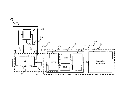
Referring to FIG. 3, an embodiment of the invention co-locates at least
one off-the-shelf RF transceiver(s) 20 together with at least one antenna(s)
22
per transceiver, and together with a signal extension apparatus 24, to form a
smart antenna assembly 26 that can be located remotely from a companion
router assembly 28. In certain embodiments of the invention, such as shown,
the
antennas 22 may be arranged in an omnidirectional array for diversity of
signal
direction and polarization. Meanwhile, plural transceivers 20 may be provided
for
diversity of signal frequency.
Co-location of transceivers 20 and antennas 22, as shown in FIG. 3,
eliminates the conventional problems with RF signal loss in long cable runs.
Instead, communications occur in the baseband domain along the long cable 30
between the router 28 and its remotely located transceiver/antenna assembly
26.
Typically, the cable 30 is unshielded twisted pair (UTP). However, coaxial
cable
is one of several conventional cable formats that also could be used.
Thus, a communication link according to an embodiment of the invention
adapts industry standard, cellular RF transceivers to "category" network
cable.
USB 2.0 is an interface protocol that is native to commercial transceivers
and routers, which in typical wireless router assemblies will be mounted in
close
proximity on a common printed wiring assembly (PWA) or motherboard. Thus,
USB connectivity is a natural choice for communication between co-located
routers and transceivers.
However, it turns out that USB suffers signal loss and packet drop at
distances in excess of 16 ft (about 5 m), so that USB connectivity between a
router and a remote transceiver presents substantially the same problems as
occur with an RF cable connection between a transceiver and a remote antenna.
6
CA 3036651 2019-03-14
Accordingly, in one aspect of the invention, the signal extension apparatus 24
reformats USB signals between the smart antenna 26 and the router 28 to a
proprietary protocol, which utilizes phase and amplitude modulation and
amplification to accomplish long range transmission of data over the network
cable 30. For example, the signal extension apparatus 24 permits
communication at distances in excess of 10 m.
The signal extension apparatus 24 also permits transmission of power and
mode-of-control signals between the transceivers 20 and the router 28, in
parallel
to the signal that encodes the USB packets, e.g., using Power over Ethernet
(PoE) or the like technology. Advantageously, this co-transmission may mask
the encoded USB packets. For example, the proprietary protocol implemented
by the signal extension apparatus 24 may provide a relatively high voltage DC
carrier signal (e.g., a constant center voltage within a range of 20 V ¨60 V),
as
well as a multi-level (i.e., more than binary) data protocol using amplitude,
phase,
and/or frequency shift keying. For example the data protocol may encode data
by selecting among three, four, or six values of carrier voltage, along with
shifting
among eight different values of frequency, thereby encoding at least a byte of
data in each time interval.
The signal extension apparatus 24 includes, in this embodiment, a pair of
custom processors 25 that are configured as format converters / boosters
("FC/Bs"). The FC/Bs 25 bi-directionally convert and multiplex/de-multiplex
between commercial USB 2.0 compliant signaling and the proprietary signaling
protocol, which in certain embodiments is a single-channel protocol, although
multi-channel signaling can also be accomplished on UTP. One of the FC/Bs 25
is disposed inside the case of the smart antenna assembly 26, and is connected
between the transceivers 20 and the network cable 30, which may be unshielded
twisted pair ("UTP") or similar commercial cable. The other of the FC/Bs 25 is
disposed inside the case of the router assembly 28, and is connected between
the network cable 30 and a router board 32.
Thus, one aspect of the invention is that the signal extension apparatus 24
enables transparent signaling between USB components, over a longer cable
7
CA 3036651 2019-03-14
distance than is possible with the native USB signal's electrical
characteristics
and communication protocol.
Another aspect of the invention is that the signal extension apparatus 24
multiplexes the USB data packets with additional auxiliary signals that are
necessary to support market available USB interfaced cellular transceiver
modules. For example, the multiplexing can be accomplished by phantom circuit
signaling in the common mode among alternate pairs of the UTP cable 30.
These auxiliary signals provide operating mode control and internal system
signaling. In typical router system implementations where remote antenna
operation is not implemented, these baseband signals simply connect between
the transceiver and the local processor.
In the inventive solution, these system signaling channels are multiplexed,
along with the operating power for the remote antenna, together on the same
cable 30 that carries the proprietary USB extension signal. In certain
embodiments the operating power channel may provide a carrier for the
baseband signal. in any case, the baseband system signal channels are not
embedded in the USB packet domain, thus, do not represent any data security
risk, since none of the USB data payload is accessible from the baseband
channels. Therefore, integrity of a secure VPN channel can be maintained via
USB.
For example, each FC/B 25 can be configured to de-multiplex multiple
data streams from the single-channel proprietary signaling protocol, and to
transmit digital signals to first and second USB connections. For example, in
the
smart antenna 26, the USB connections are direct to the transceivers 20;
whereas in the local router 28, the USB connections are between the FC/B 25
and the router processor 32. Each FC/B 25 also can be configured to multiplex
digital signals received via the first and second USB connections, and to
transmit
the multiplexed signals via network cable using the proprietary signaling
protocol.
In the other direction, the FC/B can be configured to receive a single stream
of
data from the network cable 30, and to split the stream of data into at least
two
8
CA 3036651 2019-03-14
interleaving substreams, each substream going to a different one of two or
more
RF transceivers 20 via corresponding USB connections.
In some embodiments, the paired FC/Bs can be configured to encode and
decode in such a manner as to maintain one-to-one signal correspondence
between the plurality of USB ports at the local router and the plurality of
transceivers 20 at the smart antenna. However, it is equally possible to
configure
the paired FC/Bs to shuffle the signal packets, such that there is no
reproducible
correspondence between, e.g., the signal packets at the USB ports and the
signal packets at the transceivers 20. In-the latter case, the router
processor 32
can be configured to tag each packet ¨ prior to encoding by the local router
FC/B
25¨ so that at the very far end of the wireless transmission from the smart
antenna 26, after decoding by the smart antenna FC/B 25 and after VPN
transmission via the cellular broadband network ¨ a similarly-configured
router
processor (not shown) can reconstruct the shuffled packets to obtain the same
data stream that was shuffled by the FC/Bs. It should be noted that packet
shuffling can be accomplished both among the transceivers 20 (simple
interleaving) and also timewise (limited random buffering).
In another embodiment (not shown), the connecting cable can be one or
more standard 60 Hz AC power lines connected by plugs or splices, with
powerline network adapters connecting the cable to the FC/Bs 25 in the smart
antenna 26 and at the router 28. In such an embodiment, the boost function may
be optional.
Referring to FIG. 4, working parts of the smart antenna assembly 26 are
housed in a casing that comprises a tray 34 and a lid 36. The antennas 22 are
mounted on their own PWA 38, and are connected by flex leads to the RF
transceivers 20, which are mounted on a transceiver module motherboard 40
below the antenna PWA. The RF transceivers 20 are connected via the
motherboard to the FC/B 25, also mounted on the motherboard. The FC/B 25
sends and receives USB 2.0 signals to the RF transceivers 20 while sending and
receiving the proprietary baseband signal via a network port (e.g. a standard
jack
connection 42, such as an RJ-45 plug) to the UTP cabling 30. The tray 34 may
9
CA 3036651 2019-03-14
include magnetic feet 44 for removably securing the assembly to building
structure. The motherboard 40 may include slots for receiving SIM cards 46 to
program the RF transceivers 20; alternatively, the RF transceivers may be
dedicated to pre-determined channels and modes.
Independent of the baseband protocol that is used, the router 28 and
smart antenna 26 are only a middle portion of a communications link between a
local server and a remote server, which can be established within a secured
environment such as 1Psec or VPN. In case both the local server and the remote
server are maintained in secure environments (e.g., TEMPEST certified
facilities)
then a risk of wireless penetration is substantially mitigated.
By way of example, FIG. 5 shows an enterprise scenario in which the
router 28 is securely located within a datacenter rack space 50, where it
benefits
from a well controlled environment and where network connectivity can occur in
an area with limited / controlled access. The smart antenna assembly 26 is
mounted in a location 60 where wireless signal strength will support reliable
and
predictable communications with a wireless broadband provider's base station.
In such an embodiment, it may be useful to provide within the smart
antenna assembly 26 an autonomous microprocessor 62 (e.g., an ASIC, FPGA,
RISC), as shown schematically in FIG. 6. The microprocessor within the smart
antenna should be sufficient to support autonomous event triggered reporting ¨
he. in response to a change in an operating condition of the smart antenna 26,
such as a change in the GPS signal received at a GPS antenna and chip module
64, and/or in response to a loss of power or input data signal at the FCB 25,
to
detect unapproved equipment relocation and/or to provide (via at least one
Sthe
transceivers 20) periodic alerts such as pings of positional reporting. Such
periodic pings will require onboard the smart antenna 26 an energy storage
device 66 (e.g. a battery, ultracapacitor, or the like).
Additionally, it may be desirable to provide onboard the smart antenna 26
a wireless (e.g., IEEE 802.11) hotspot 68 for open data (i.e. use by customers
or
general public), unrelated to the companion router 28 that transmits secured
data. Provision of the duplicate transceivers 20, transmitting on different
CA 3036651 2019-03-14
channels and possibly to different providers, can permit total separation of
open
data from secured data.
Following from the idea of the wireless hotspot 68, it also may be useful
(as further shown in FIG. 6) to substitute for the connecting cable 30 a
wireless
connection 70, using, e.g., a proprietary encrypted packeting scheme
transmitted
on 802.11-compliant frames. In such case, the signal extension apparatus 24
then will incorporate, in place of the FC/Bs 25, wireless modules 75 that
implement a proprietary multi-band protocol for multiplexing the auxiliary
signals
and the USB data packets mentioned above. For example, each of the wireless
modules may be compliant with IEEE 802.11. Further, the smart antenna 26
then will require local power (not shown) in place of power previously
provided
via the now-absent connecting cable. At the other end of wireless connection
70
(router 28, not shown in FIG. 7), a similar wireless module 75 will be
provided.
Thus, relying on the security of the proprietary protocol implemented by
the wireless modules 75, the secure wireless connection 70 can be used in
place
of the network ports 42 and connecting cable 30 that were discussed above with
reference to FIG, 3.
Although exemplary embodiments of the invention have been described
with reference to drawings, those skilled in the art will apprehend various
changes in form and detail consistent with the scope of the invention as
defined
by the appended claims. For example, although a jack connection and UTP
cabling are conventional for local area networks, it is equally feasible to
provide
screw terminal connections or coaxial cable or the like alternatives.
11
CA 3036651 2019-03-14