Language selection

Search

Patent 3036793 Summary

Third-party information liability

Some of the information on this Web page has been provided by external sources. The Government of Canada is not responsible for the accuracy, reliability or currency of the information supplied by external sources. Users wishing to rely upon this information should consult directly with the source of the information. Content provided by external sources is not subject to official languages, privacy and accessibility requirements.

Claims and Abstract availability

Any discrepancies in the text and image of the Claims and Abstract are due to differing posting times. Text of the Claims and Abstract are posted:

  • At the time the application is open to public inspection;
  • At the time of issue of the patent (grant).
(12) Patent Application: (11) CA 3036793
(54) English Title: OFFICE CHAIR WITH SYNCHRONOUSLY MOVABLE BACKREST AND SEAT
(54) French Title: CHAISE DE BUREAU EQUIPEE D`UN DOSSIER ET D`UN SIEGE DEPLACABLES DE MANIERE SYNCHRONISEE
Status: Examination
Bibliographic Data
(51) International Patent Classification (IPC):
  • A47C 03/026 (2006.01)
  • A47C 01/032 (2006.01)
  • A47C 07/14 (2006.01)
(72) Inventors :
  • COSTAGLIA, MASSIMO (Italy)
(73) Owners :
  • REXSITT ITALIA S.R.L.
(71) Applicants :
  • REXSITT ITALIA S.R.L. (Italy)
(74) Agent: ROBIC AGENCE PI S.E.C./ROBIC IP AGENCY LP
(74) Associate agent:
(45) Issued:
(22) Filed Date: 2019-03-13
(41) Open to Public Inspection: 2019-12-14
Examination requested: 2024-03-07
Availability of licence: N/A
Dedicated to the Public: N/A
(25) Language of filing: English

Patent Cooperation Treaty (PCT): No

(30) Application Priority Data:
Application No. Country/Territory Date
202018000002761 (Italy) 2018-06-14

Abstracts

English Abstract


A chair in which a synchronized mechanism, fixed on a telescopic
post of a base, supports and renders interdependent rigid elements and
which, define respectively the backrest and the seat of the chair and are
mutually hinged at a first point, i.e. along a horizontal axis perpendicular
to
the longitudinal centerline plane of the seating space, which is entirely
defined by a single curved line obtained by joining the rigid elements and
which are adapted for this purpose.


Claims

Note: Claims are shown in the official language in which they were submitted.

5
CLAIMS:
1. An office chair with synchronously movable backrest and seat, of
the type that has a backrest and a seat which are supported and rendered
interdependent by a synchronized mechanism fixed on a telescopic post of a
base, wherein said backrest and said seat are rigid elements and the seating
space is entirely defined by a single curved line which is obtained by joining
said rigid elements, and said rigid elements being coupled mutually with a
hinge, along a horizontal axis perpendicular to the longitudinal centerline
plane of the seating space.
2. The office chair with synchronously movable backrest and seat
according to claim 1, wherein two mirror-symmetrical portions protrude
forward, in a front region, from the rigid element that defines the backrest,
which is pivoted on a rotatable joint in the synchronized mechanism and
elastically countered at a point, and said two mirror-symmetrical portions
are contoured and adapted for hinging by way of the hinge of the rigid
element that defines the seat.
3. The office chair with synchronously movable backrest and seat
according to claim 1, wherein the rigid element that defines the seat, which
is coupled in a front region to the underlying synchronized mechanism by
two first bushings which are hinged in the rigid element that defines the
seat and by two second bushings which are integral with the first bushings
and are hinged to the sides of the synchronized mechanism, has two mirror-
symmetrical arms which protrude rearward, in a rear region, for a rotatable
coupling thereof to the two mirror-symmetrical portions of the rigid
structure by way of the hinges, thus completing the curved line of the
seating space.
4. The office chair with synchronously movable backrest and seat
according to claim 1, wherein a seating surface of the seating space is
obtained from a single flexible element, made from net, from fabric or other
suitable material and optionally padded, which is affixed to said curved line

6
and which extends from the backrest to the seat without discontinuities.
5. The office chair with synchronously movable backrest and seat
according to claim 3, wherein the backrest, the seat, and the synchronized
mechanism are connected to each other by a pair of articulated
quadrilaterals that are mutually mirror-symmetrical and are defined by the
horizontal hinging axes of the rotatable joint, of the hinge, of the two first
bushings and of the two second bushings so that a rearward rotation of the
backrest about the pin of the mechanism determines the entrainment of the
seat which, pivoted at a first point, by translating rearward forces the two
first bushings, which is pivoted in the seat, to follow it, thus rotating the
two
second bushings, which are integral with the two first bushings and are
pivoted in the synchronized mechanism.

Description

Note: Descriptions are shown in the official language in which they were submitted.


OFFICE CHAIR WITH SYNCHRONOUSLY MOVABLE BACKREST
AND SEAT
The present invention relates to an office chair with synchronously
movable backrest and seat.
It is always desirable that an office chair, in addition to being
rotatable and height-adjustable, can also be capable of adapting,
automatically and ergonomically, to the various different positions assumed
by the user during the various phases of work: intense, normal and relaxed.
For this to happen, it is necessary first of all that the backrest and the
seat of a chair incline simultaneously but describing different angular
rotations.
To this end, operators in the sector have for some time availed of a
specially-designed synchronized mechanism, available on the market in the
same way as castor wheels and other accessories.
Such mechanism is placed on the telescopic post of the base, with or
without wheels, in order to support the backrest and the seat and make them
interdependent so that their movements, simultaneous but different, are
mutually linked on the basis of the specific connection of the synchronized
mechanism used to connect them.
Unfortunately most office chairs, with or without the above
mentioned mechanism, are penalized by the fact that the backrest and the
seat only partially support the movements of the body of the user, as they
are not capable of exactly reproducing the fulcrums of the human body.
This is demonstrated by the fact that, when varying the configuration
of the chair, the user perceives the unpleasant sensation of being not
properly and constantly supported during the full travel of the mechanism,
and feels that the back and the lumbar region enjoy proper support only
when the configuration of the backrest is proximate to the vertical.
This can be ascribed especially to the fact that the seat and the
backrest, which are both connected to the same synchronized mechanism
CA 3036793 2019-03-13

2
but not to each other, are designed to move further apart from each other
during the transition of the backrest from the erect configuration to an
increasingly reclined one.
It should be noted that, to date, the only office chairs that have the
seat and the backrest directly connected to each other are monocoque chairs
which, as such, do not allow the use of the above mentioned synchronized
mechanism, since it is not conceivable that two parts, rigidly connected to
each other, could be moved in a mutually different manner.
The aim of the present invention is to devise an office chair that has a
to backrest and a seat which, by moving synchronously, best support the
movements of the body of the user.
Within this aim, an object of the present invention is to devise an
office chair that provides a backrest and a seat that are linked by a
synchronized mechanism and are shaped and connected to each other in an
unusual manner.
This aim and this object and others that will become better apparent
hereinafter are achieved by a chair as defined in claim 1.
Further characteristics and advantages of the chair according to the
invention will be more evident by the description of a preferred embodiment
of the chair, illustrated by way of example in the following drawings,
wherein:
- Figure 1 is a perspective exploded view of a chair according to an
embodiment of the present invention;
- Figures 2 and 3 are side views of the same side of the assembled
chair of the invention, in two limit configurations of its use.
With reference to the figures it is possible to see that the principal
characteristic of the invention consists of having the seat and the backrest
stably and directly connected to each other, notwithstanding the different
and linked movement of the two elements in the passage of the chair from
one limit configuration to the other, i.e. from the configuration in Figure 2
CA 3036793 2019-03-13

3
to the configuration in Figure 3 and viceversa.
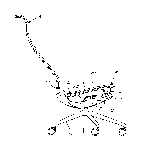
In fact, the seating space of the chair according to the invention is
entirely defined by a single curved line obtained by joining rigid elements A
and B which define respectively the backrest and the seat of the chair and
are mutually hinged at a first point 2, i.e. along a horizontal axis
perpendicular to the longitudinal centerline plane of the seating space.
In any case the invention consists of an adapted hinging, adjacent to
an overlying flexible covering element in order to contain the stretching
thereof when reclining the backrest.
In fact the covering element, which consists of a net, a sheet or other
adapted material and is optionally padded, is in any case fixed to the curved
line that defines and delimits the seating space, extending from the backrest
A to the seat B without discontinuities.
As previously mentioned, the chair according to the present invention,
like other conventional chairs, is provided with a synchronized mechanism
C which, mounted on a telescopic post D1 of a base D, supports the rigid
structure A of the backrest and the rigid structure B of the seat while also
rendering their different and linked movements interdependent.
The rigid element or structure A, which acts as the backrest in a
region above two mirror-symmetrical portions Al which protrude toward
the rigid structure B that defines the seat to be hinged at the first point or
hinge 2, continues under the above mentioned seat, which comes around
from the rear, in order to straddle the mechanism C with two mirror-
symmetrical portions A2 that are hinged horizontally at a rotatable joint 1
and contrasted elastically at a second point 5 by a system of springs present
inside the mechanism for springing the backrest.
The rigid element or structure B that defines the seat, which is
coupled in a front region to the underlying mechanism C by two bushings 3
which are hinged in the seat and by two bushings 4 which are integral with
the first bushings and are hinged to the sides of the mechanism, has two
CA 3036793 2019-03-13

4
mirror-symmetrical arms B1 which protrude rearward in order to be hinged
at the first point 2 to the portions Al of the rigid structure A and thus
complete the curved line of the seating space.
As a consequence, every movement of the backrest A produces a
simultaneous but different movement of the seat B, both being connected,
together with the synchronized mechanism C, by a pair of articulated
quadrilaterals that are mutually mirror-symmetrical and are defined by the
horizontal hinging axes that pass through the points respectively defined by
a pin 1 of the mechanism C, the first point 2, the bushings 3 and the
bushings 4.
In fact, the rearward rotation of the backrest A about the pin point 1
of the mechanism C determines the entrainment of the seat B which, pivoted
at the first point or hinge 2, by translating rearward forces the bushing 3,
which is pivoted in the seat, to follow it, thus rotating the bushing 4, which
is is integral with the bushing 3 and is pivoted in the synchronized mechanism
C.
While all this goes on, the rearward rotation of the backrest A and the
movements that depend on this are contrasted at the second point 5 by the
system of springs with which the synchronized mechanism C is provided in
order to automatically support the movements of the body of the user,
moreover guaranteeing the user, by virtue of the constant connection of the
seat to the backrest, the broadest possible resting surface, which is
essential
in order to prevent areas of excessive pressure from blocking and reducing
the flow of blood and causing muscle pains.
The armrests, if any, howsoever shaped, will be fixed to the rigid
structure of the backrest A, it being necessary that they accompany any
variation in trim thereof with respect to the seat B.
CA 3036793 2019-03-13

Representative Drawing
A single figure which represents the drawing illustrating the invention.
Administrative Status

2024-08-01:As part of the Next Generation Patents (NGP) transition, the Canadian Patents Database (CPD) now contains a more detailed Event History, which replicates the Event Log of our new back-office solution.

Please note that "Inactive:" events refers to events no longer in use in our new back-office solution.

For a clearer understanding of the status of the application/patent presented on this page, the site Disclaimer , as well as the definitions for Patent , Event History , Maintenance Fee  and Payment History  should be consulted.

Event History

Description Date
Letter Sent 2024-03-11
Request for Examination Received 2024-03-07
Request for Examination Requirements Determined Compliant 2024-03-07
All Requirements for Examination Determined Compliant 2024-03-07
Small Entity Declaration Determined Compliant 2024-03-07
Small Entity Declaration Request Received 2024-03-07
Common Representative Appointed 2020-11-07
Application Published (Open to Public Inspection) 2019-12-14
Inactive: Cover page published 2019-12-13
Common Representative Appointed 2019-10-30
Inactive: First IPC assigned 2019-03-26
Inactive: IPC assigned 2019-03-26
Inactive: Filing certificate - No RFE (bilingual) 2019-03-26
Inactive: IPC assigned 2019-03-26
Inactive: Applicant deleted 2019-03-21
Application Received - Regular National 2019-03-19

Abandonment History

There is no abandonment history.

Maintenance Fee

The last payment was received on 2024-03-04

Note : If the full payment has not been received on or before the date indicated, a further fee may be required which may be one of the following

  • the reinstatement fee;
  • the late payment fee; or
  • additional fee to reverse deemed expiry.

Patent fees are adjusted on the 1st of January every year. The amounts above are the current amounts if received by December 31 of the current year.
Please refer to the CIPO Patent Fees web page to see all current fee amounts.

Fee History

Fee Type Anniversary Year Due Date Paid Date
Application fee - standard 2019-03-13
MF (application, 2nd anniv.) - standard 02 2021-03-15 2021-03-01
MF (application, 3rd anniv.) - standard 03 2022-03-14 2022-02-28
MF (application, 4th anniv.) - standard 04 2023-03-13 2023-02-27
MF (application, 5th anniv.) - standard 05 2024-03-13 2024-03-04
Request for examination - small 2024-03-13 2024-03-07
Owners on Record

Note: Records showing the ownership history in alphabetical order.

Current Owners on Record
REXSITT ITALIA S.R.L.
Past Owners on Record
MASSIMO COSTAGLIA
Past Owners that do not appear in the "Owners on Record" listing will appear in other documentation within the application.
Documents

To view selected files, please enter reCAPTCHA code :


To view images, click a link in the Document Description column (Temporarily unavailable). To download the documents, select one or more checkboxes in the first column and then click the "Download Selected in PDF format (Zip Archive)" or the "Download Selected as Single PDF" button.

List of published and non-published patent-specific documents on the CPD .

If you have any difficulty accessing content, you can call the Client Service Centre at 1-866-997-1936 or send them an e-mail at CIPO Client Service Centre.

({010=All Documents, 020=As Filed, 030=As Open to Public Inspection, 040=At Issuance, 050=Examination, 060=Incoming Correspondence, 070=Miscellaneous, 080=Outgoing Correspondence, 090=Payment})


Document
Description 
Date
(yyyy-mm-dd) 
Number of pages   Size of Image (KB) 
Abstract 2019-03-12 1 13
Description 2019-03-12 4 182
Claims 2019-03-12 2 69
Drawings 2019-03-12 3 57
Representative drawing 2019-11-06 1 7
Maintenance fee payment 2024-03-03 43 1,773
Request for examination 2024-03-06 5 160
Small entity declaration 2024-03-06 6 265
Filing Certificate 2019-03-25 1 204
Courtesy - Acknowledgement of Request for Examination 2024-03-10 1 424