Language selection

Search

Patent 3037084 Summary

Third-party information liability

Some of the information on this Web page has been provided by external sources. The Government of Canada is not responsible for the accuracy, reliability or currency of the information supplied by external sources. Users wishing to rely upon this information should consult directly with the source of the information. Content provided by external sources is not subject to official languages, privacy and accessibility requirements.

Claims and Abstract availability

Any discrepancies in the text and image of the Claims and Abstract are due to differing posting times. Text of the Claims and Abstract are posted:

  • At the time the application is open to public inspection;
  • At the time of issue of the patent (grant).
(12) Patent Application: (11) CA 3037084
(54) English Title: FILL PROBE ATTACHMENT HAVING ELONGATE GAS-GUIDING ELEMENT
(54) French Title: ELEMENT RAPPORTE DE SONDE A REMPLISSAGE COMPORTANT UN ELEMENT ALLONGE DE GUIDAGE DE GAZ
Status: Examination
Bibliographic Data
(51) International Patent Classification (IPC):
  • G01M 03/20 (2006.01)
(72) Inventors :
  • DECKER, SILVIO (Germany)
(73) Owners :
  • INFICON GMBH
(71) Applicants :
  • INFICON GMBH (Germany)
(74) Agent: PERRY + CURRIER
(74) Associate agent:
(45) Issued:
(86) PCT Filing Date: 2017-09-18
(87) Open to Public Inspection: 2018-03-22
Examination requested: 2022-06-23
Availability of licence: N/A
Dedicated to the Public: N/A
(25) Language of filing: English

Patent Cooperation Treaty (PCT): Yes
(86) PCT Filing Number: PCT/EP2017/073404
(87) International Publication Number: EP2017073404
(85) National Entry: 2019-03-15

(30) Application Priority Data:
Application No. Country/Territory Date
10 2016 217 891.1 (Germany) 2016-09-19

Abstracts

English Abstract

The invention relates to a sniffer probe (22) for a gas analyzer, wherein the sniffer probe (22) is designed to suction gas and can be connected to the gas analyzer and wherein the sniffer probe (22) has a sniffer tip (20) provided with a suction opening, such that gas is suctioned through the suction opening along a central perpendicular (28) to the suction opening, characterized in that the sniffer tip (20) has at least one elongate gas-guiding element (30), which is arranged substantially parallel to the central perpendicular (28) and distally protrudes beyond the suction opening.


French Abstract

L'invention concerne une sonde de reniflage (22) d'un analyseur de gaz, conçue pour aspirer du gaz et pouvant être reliée à l'analyseur de gaz. La sonde de reniflage (22) présente une pointe de reniflage (20) pourvue d'une ouverture d'aspiration de telle manière que du gaz est aspiré le long d'une médiatrice (28) de l'ouverture d'aspiration, à travers l'ouverture d'aspiration. L'invention est caractérisée en ce que la pointe de reniflage (20) présente au moins un élément (30) allongé guidant les gaz, disposé sensiblement parallèlement à la médiatrice (28) et faisant saillie de façon distale par rapport à l'ouverture d'aspiration.

Claims

Note: Claims are shown in the official language in which they were submitted.

6
Claims
1. Sniffer probe (22) of a gas analyzer, wherein the sniffer probe (22) is
con-
figured to draw in gas and is adapted to be connected to the gas analyzer,
and wherein the sniffer probe (22) comprises a sniffer tip (20) having with
an intake opening, such that gas is drawn in through the intake opening
along a perpendicular bisector (28) of the intake opening,
characterized in that
the sniffer tip (20) comprises at least one elongated gas-guiding element
(30) arranged substantially parallel to the perpendicular bisector (28) and
protruding distally beyond the intake opening.
2. Sniffer attachment (12) to be mounted to the sniffer tip (20) of a
sniffer
probe (22) of a gas analyzer, wherein the sniffer probe is configured to draw
in gas, wherein the sniffer attachment (12) comprises an intake opening
adapted to be aligned with the intake opening of the sniffer tip (20), such
that gas can be drawn in along a perpendicular bisector (28) of both intake
openings,
characterized in that
the sniffer attachment (12) comprises at least one elongated gas-guiding
element (30) arranged substantially parallel to the perpendicular bisector
(28) and protruding distally beyond the intake opening (26).
3. Sniffer probe (22) of claim 1 or 2, characterized in that the elongated
ele-
ment (30) is elastic.
4. Sniffer probe (22) of one of claims 1 to 3, characterized in that the
elongated
element (30) comprises a gas-permeable material covering the intake open-
ing or arranged adjacent the intake opening.

7
5. Sniffer probe (22) of one of claims 1 to 4, characterized in that a
plurality
of elongated elements (30) is arranged annularly around the intake opening.
6. Sniffer probe (22) of claim 5, characterized in that a plurality of
elongated
elements (30) in the form of thin fibers are provided in the manner of a
paintbrush.

Description

Note: Descriptions are shown in the official language in which they were submitted.


CA 03037084 2019-03-15
Fill probe attachment having elongate gas-guiding element
The invention relates to a sniffer probe of a gas analyzer configured to draw
gas,
as well as to a sniffer attachment for such a sniffer probe.
For generating a vacuum, a gas analyzer is provided with a vacuum pump to draw
gas into the vacuum. The gas drawn in is analyzed in order to identify at
least one
component of the gas drawn in. The vacuum pump of the gas analyzer is
connected
with the sniffer probe, typically via an elongated flexible hose, so as to be
able to
guide the sniffer probe in the target region. The gas is drawn in through the
intake
opening of the sniffer tip along a perpendicular bisector of the intake
opening, the
intake opening being provided distally on the sniffer probe. Such gas
analyzers are
typically used for leak detection, wherein the sniffer probe is most often
guided
manually over a region to be tested for a possible leak. The sniffer probe
may, for
example, be guided over a test object in which a test gas is used to
pressurize the
object with respect to the surrounding atmosphere, so as to detect test gas
escap-
ing through a possible leak.
It is a basic difficulty in the detection of leaks that, for detecting a leak,
it is con-
ventionally desired that a strong flow of the gas flow drawn in through the
sniffer
probe is obtained already at a great distance. However, the greater the gas
flow
drawn in, the lower is the concentration of the detected test gas in the gas
flow
drawn in and the lower is the detection limit for the test gas. In addition,
air flows
transversal to the intake direction of the sniffer probe may have the effect
that a
part of the test gas escaping from a leak is carried away from the sniffer tip
and is
not detected by the gas analyzer. This effect reduces the detection limit for
the
test gas the more, the greater the distance is between a leak and the sniffer
tip.

CA 03037084 2019-03-15
2
It is an object of the present invention to provide an improved sniffer probe
and
an improved sniffer attachment.
The object is achieved with the features of claims 1 and 2.
The sniffer probe is provided with at least one elongated gas-guiding element.
As
an alternative, a sniffer attachment is provided which is adapted to be
mounted
on the sniffer probe and is provided with the at least one elongated element.
With
respect to the elongated element, gas-guiding means that air or gas flows
trans-
versal to the opening area of the intake opening, i.e. perpendicular to the
perpen-
dicular bisector of the intake opening, are affected by the elongated element.
This
is to avoid that such transversal flows carry test gas away from the intake
opening
or prevent the same from being drawn into the intake opening. Here, the
elongated
element is arranged substantially in parallel with the perpendicular bisector
of the
intake opening along which the gas is drawn in, so that the intake of the gas
through the intake opening along the perpendicular bisector is compromised as
little as possible. As used herein, substantially refers to an inclined
arrangement
in an angular range of up to 20 degrees, preferably up to 10 degrees and
particu-
larly preferred up to 5 degrees with respect to the parallel line. It is
preferred that
the elongated element affects transversal flows more than gas flows along the
perpendicular bisector. The elongated element may also serve to reduce gas tur-
bulences. This results in the advantage that the proportion of test gas in the
gas
flow drawn in is increased due to the reduced transversal flows and that the
de-
tection limit for the detection of test gas in the gas flow drawn in is
lowered.
The elongated element is an element whose longitudinal dimension along the per-
pendicular bisector is larger than its width or depth transverse to the
perpendicular
bisector. The elongated element may be a two-dimensional sheet-like element
whose depth is significantly smaller than its width, the width being smaller
than
its length. As an alternative, the element may be a fiber-like cylindrical
element.
This may, for example, be a fiber with a round cross section. Preferably, a
plurality
of elongated elements of the above described kind is arranged adjacent the
intake
opening so as to form a barrier to transversal flows. Advantageously, the
elongated

CA 03037084 2019-03-15
,
3
elements are distributed around the intake opening, e.g. in an annular manner.
Thus, transversal flows from any possible direction transverse to the
perpendicular
bisector of the plane of the intake opening are affected, while the gas flow
in the
longitudinal direction along the perpendicular bisector is affected only
slightly. The
elongated elements are preferably designed to be elastically resilient. In the
case
of elongated fibers, this results a paintbrush-like structure for preventing
trans-
versal flows and for direction the gas flow along the fibers.
The elongated element extends distally beyond the intake opening, so that the
gas
drawn in flows past the elongated element before it reaches the intake
opening.
In the case of elastically resilient elongated elements or a resilient elastic
element,
the same may also serve as an indicator for adjusting and maintaining a
suitable
distance from the surface of the test object being sniffed. The length of the
elon-
gated element protruding distally beyond the intake opening should correspond
to
the optimal distance between the intake opening and the surface to be sniffed.
Upon contact between the distal ends of the elongated elements and the surface
sniffed, the elongated elements provide a haptically noticeable resistance.
It is conceivable to provide the distal end of at least one elongated element
with a
touch-sensitive sensor which, upon contact with the surface to be sniffed,
gener-
ates a signal that indicates that the sniffer tip maintains the correct
distance from
the test object. The signal may be generated in a manner known per se, e.g.
electronically, and be transmitted to the gas analyzer.
In another embodiment it is conceivable that the elongated gas-guiding element
is made of a gas-permeable, e.g. sponge-like material. Advantageously, the gas
permeability is greater in the longitudinal direction of the elongated
element, i.e.
in the gas intake direction parallel to the perpendicular bisector of the
intake open-
ing plane, than it is in the direction transversal to the longitudinal
direction, so as
to affect transversal flows of the gas more than longitudinal flows. The gas-
per-
meable material of the elongated element may cover the intake opening so that
the drawn gas is drawn in through the material. In this case, it is
particularly
advantageous if the gas permeability is greater in the longitudinal direction
than

CA 03037084 2019-03-15
4
in the transversal direction. As an alternative, the elongated element may
also be
arranged adjacent the intake opening, e.g. in form of a shield shielding off
trans-
versal flows in the manner of a windshield. An arrangement of a plurality of
elon-
gated elements of a gas-permeable material of the above described type is also
conceivable.
The following is a detailed explanation of embodiments of the invention with
ref-
erence to the Figures. In the Figures:
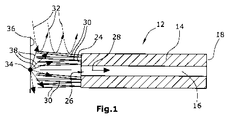
Fig. 1 is a longitudinal section through a sniffer attachment (first
embodi-
ment),
Fig. 2 an illustration of a sniffer probe with the sniffer attachment of
Fig. 1,
Fig. 3 a longitudinal section through a sniffer probe (second embodiment),
and
Fig. 4 an illustration of the sniffer probe of Fig. 3.
The sniffer attachment 12 of the first embodiment has a cylindrical housing 14
provided with a flow channel for the gas flow drawn in, the flow channel
extending
centrally through the housing 14. At the proximal, i.e. the downstream end 18,
seen in the gas flow direction of the gas flow drawn in, the sniffer
attachment 12
may be set on the sniffer tip 20 of a sniffer probe 22, as illustrated in Fig.
2. For
this purpose, the sniffer attachment 12 and the sniffer probe 22 can be
provided
with complementary interlocking connector elements not illustrated in the
Figures.
At the distal end 24 opposite the proximal end 18, the sniffer attachment 12
is
provided with an intake opening 26 opening into the gas flow channel 16. At
least
for the greater part, the gas is drawn in through the intake opening 26 along
the
perpendicular bisector 28, i.e. in an intake direction parallel to a straight
line ar-
ranged perpendicular to the surface of the intake opening 26 and extending
through the centre of the intake opening 26.

CA 03037084 2019-03-15
, 5 .
The distal end 24 is provided with a plurality of fiber-like elongated
elements 30
which protrude as thin fibers in a paintbrush-like manner from the distal end
24
and extend distally.
While the first embodiment in Figures 1 and 2 is characterized by providing
the
sniffer tip 20 of a sniffer probe 22 with a sniffer attachment 12 having the
elon-
gated elements, the second embodiment in Figures 3 and 4 is based on the idea
to attach the elongated elements directly to the sniffer tip 20. In the first
embod-
iment a plurality of elongated elements is arranged in the region of the
intake
opening 26 of the sniffer attachment 12 and extends beyond this intake opening
24. In the second embodiment the elongated elements are arranged in the region
of the intake opening 25 of the sniffer tip 20 and extend distally beyond the
same.
The elongated elements 30 form a barrier to transversal flows 32 directed
trans-
versally or almost transversally to the perpendicular bisector 28, the barrier
being
distributed annularly around the intake opening 26 and 25, respectively. The
gas
permeability of this barrier is significantly higher, and preferably maximal,
in the
longitudinal direction along the perpendicular bisector 28 and is
significantly lower,
and preferably negligibly low, for transversal flows 32 directed transversally
to the
perpendicular bisector 28.
Figures 1 and 3 schematically illustrate a leak 34 in the surface 36 to be
sniffed,
the star-shaped arrangement of arrows 38 indicating the test gas flowing from
the
leak 34. The elongated elements 30 avoid that transversal gas flows 32 carry
the
escaping test gas 38 away from the intake opening 26. When the elongated ele-
ments 30 contact the surface 36 to be sniffed in the region of the leak 34,
the gas
38 escaping from the leak 34 is directed in the longitudinal direction along
the
perpendicular bisector 28 to the intake opening 26 or 25 and flows from there
through the gas flow channel 16 to the gas analyzer for evaluation, the gas
ana-
lyzer not being illustrated in the Figures.

Representative Drawing
A single figure which represents the drawing illustrating the invention.
Administrative Status

2024-08-01:As part of the Next Generation Patents (NGP) transition, the Canadian Patents Database (CPD) now contains a more detailed Event History, which replicates the Event Log of our new back-office solution.

Please note that "Inactive:" events refers to events no longer in use in our new back-office solution.

For a clearer understanding of the status of the application/patent presented on this page, the site Disclaimer , as well as the definitions for Patent , Event History , Maintenance Fee  and Payment History  should be consulted.

Event History

Description Date
Amendment Received - Response to Examiner's Requisition 2024-01-08
Amendment Received - Voluntary Amendment 2024-01-08
Examiner's Report 2023-09-19
Inactive: Report - No QC 2023-09-01
Amendment Received - Voluntary Amendment 2022-07-19
Letter Sent 2022-07-19
All Requirements for Examination Determined Compliant 2022-06-23
Request for Examination Requirements Determined Compliant 2022-06-23
Request for Examination Received 2022-06-23
Common Representative Appointed 2020-11-07
Common Representative Appointed 2019-10-30
Inactive: Notice - National entry - No RFE 2019-03-28
Inactive: Cover page published 2019-03-25
Application Received - PCT 2019-03-21
Inactive: IPC assigned 2019-03-21
Inactive: First IPC assigned 2019-03-21
National Entry Requirements Determined Compliant 2019-03-15
Amendment Received - Voluntary Amendment 2019-03-15
Application Published (Open to Public Inspection) 2018-03-22

Abandonment History

There is no abandonment history.

Maintenance Fee

The last payment was received on 2023-08-16

Note : If the full payment has not been received on or before the date indicated, a further fee may be required which may be one of the following

  • the reinstatement fee;
  • the late payment fee; or
  • additional fee to reverse deemed expiry.

Patent fees are adjusted on the 1st of January every year. The amounts above are the current amounts if received by December 31 of the current year.
Please refer to the CIPO Patent Fees web page to see all current fee amounts.

Fee History

Fee Type Anniversary Year Due Date Paid Date
Basic national fee - standard 2019-03-15
MF (application, 2nd anniv.) - standard 02 2019-09-18 2019-08-28
MF (application, 3rd anniv.) - standard 03 2020-09-18 2020-09-01
MF (application, 4th anniv.) - standard 04 2021-09-20 2021-08-26
Request for examination - standard 2022-09-19 2022-06-23
MF (application, 5th anniv.) - standard 05 2022-09-19 2022-08-16
MF (application, 6th anniv.) - standard 06 2023-09-18 2023-08-16
Owners on Record

Note: Records showing the ownership history in alphabetical order.

Current Owners on Record
INFICON GMBH
Past Owners on Record
SILVIO DECKER
Past Owners that do not appear in the "Owners on Record" listing will appear in other documentation within the application.
Documents

To view selected files, please enter reCAPTCHA code :


To view images, click a link in the Document Description column. To download the documents, select one or more checkboxes in the first column and then click the "Download Selected in PDF format (Zip Archive)" or the "Download Selected as Single PDF" button.

List of published and non-published patent-specific documents on the CPD .

If you have any difficulty accessing content, you can call the Client Service Centre at 1-866-997-1936 or send them an e-mail at CIPO Client Service Centre.


Document
Description 
Date
(yyyy-mm-dd) 
Number of pages   Size of Image (KB) 
Description 2024-01-07 5 331
Claims 2024-01-07 4 217
Description 2019-03-14 5 223
Claims 2019-03-14 2 40
Abstract 2019-03-14 1 14
Representative drawing 2019-03-14 1 8
Drawings 2019-03-14 2 23
Claims 2019-03-15 3 115
Amendment / response to report 2024-01-07 17 717
Notice of National Entry 2019-03-27 1 192
Reminder of maintenance fee due 2019-05-21 1 111
Courtesy - Acknowledgement of Request for Examination 2022-07-18 1 423
PCT Correspondence 2023-05-16 3 146
PCT Correspondence 2023-06-18 3 146
PCT Correspondence 2023-07-17 3 145
PCT Correspondence 2023-08-16 3 146
PCT Correspondence 2023-09-15 3 146
Examiner requisition 2023-09-18 5 289
International search report 2019-03-14 2 53
National entry request 2019-03-14 4 95
Amendment - Abstract 2019-03-14 2 80
Prosecution/Amendment 2019-03-14 2 36
Voluntary amendment 2019-03-14 5 118
Request for examination 2022-06-22 3 118
PCT Correspondence 2023-01-19 3 147
PCT Correspondence 2023-02-18 3 146
PCT Correspondence 2023-03-18 3 146
PCT Correspondence 2023-04-17 3 146