Note: Descriptions are shown in the official language in which they were submitted.
- 1 -
WIRELESS CONNECTIVITY IN A RADAR DETECTOR
[0001] This application is a division of Canadian Patent Application No.
2,753,309
filed, February 22, 2010.
Field of the Invention
[0002] The present invention relates to radar detectors.
Background of the Invention
[0003] Radar detectors warn drivers of the use of police radar, and the
potential for
traffic law citations if the driver exceeds the speed limit. The FCC has
allocated several
regions of the electromagnetic spectrum for police radar use. The bands used
by police radar
are generally known as the X, K and Ka bands. Each relates to a different part
of the
spectrum. The X and K bands are relatively narrow frequency ranges, whereas
the Ka band
is a relatively wide range of frequencies. By the early 1990's, police radar
evolved to the
point that it could operate almost anywhere in the 1600-megahertz wide Ka
band. During
that time radar detectors kept pace with models that included descriptive
names like "Ultra
Wide" and "Super Wide." More recently, police have begun to use laser
(optical) systems for
detecting speed. This technology was termed LIDAR for "LIght Detection And
Ranging."
[0004] Radar detectors typically comprise a microwave receiver and
detection
circuitry that is typically realized with a microprocessor or digital signal
processor (DSP).
Microwave receivers are generally capable of detecting microwave components in
the X, K,
and very broad Ka band. In various solutions, either a microprocessor or DSP
is used to make
decisions about the signal content from the microwave receiver. Systems
including a digital
signal processor have been shown to provide superior performance over
solutions based on
conventional microprocessors due to the DSP's ability to find and distinguish
signals that are
buried in noise. Various methods of applying DSP's were disclosed in U.S.
Patent Nos.
4,954,828, 5,079,553, 5,049,885, and 5,134,406.
CA 3037278 2019-03-20
- 2 -
[0005] Police use of laser has also been countered with laser detectors,
such as described in
U.S. Patent Nos. 5,206,500, 5,347,120 and 5,365,055. Products are now
available that combined
laser detection into a single product with a microwave receiver, to provide
comprehensive protection.
[0006] The DSP or microprocessor in a modern radar detector is
programmable.
Accordingly, it can be instructed to manage all of the user interface features
such as input switches,
lights, sounds, as well as generate control and timing signals for the
microwave receiver and/or laser
detector. Early in the evolution of the radar detector, consumers sought
products that offered a better
way to manage the audible volume and duration of warning signals. Good
examples of these
solutions are found in U.S. Patent Nos. 4,631,542, 5,164,729, 5,250,951, and
5,300,932, which
provide methods for conditioning the response generated by the radar detector.
[0007] Methods for conditioning detector response are gaining importance,
because there are
an increasing number of signals present in the X, K, and Ka bands from
products that are completely
unrelated to police radar. These products share the same regions of the
spectrum and are also
licensed by the FCC. The growing number of such signals is rapidly undermining
the credibility of
radar detector performance. Radar detectors cannot tell the difference between
emissions from many
of these devices and true police radar systems. As a result, radar detectors
are increasingly generating
false alarms, effectively "crying wolf', reducing the significance of warnings
from radar detectors.
Among the possible sources of false alarms are microwave door openers, public
safety systems such
as ARTEMIS, and other radar detectors. At this time, there are very few signal
sources that can cause
false laser detections in comparison to the substantial list of false
microwave signals just described.
However certain locations near airports have been demonstrated to cause such
problems for various
laser detector products. The issue of false signals and ways of addressing
geographically fixed false
sources, is addressed in the above-referenced U.S. patent 6,670,905, in which
the characteristics of
false sources are stored with reference to the GPS-based location of the
source, so that in subsequent
encounters the false source may be ignored or the response to that source
conditioned.
[0008] Vehicle electronics continue to increase in sophistication; GPS
receivers and satellite
receivers are now commonplace. Furthermore, wireless (typically Bluetooth)
connectivity to cellular
telephones and cellular networks has become commonplace, permitting hands free
operation and in
some circumstances, Internet or text messaging (SMS) connectivity within the
vehicle electronic
systems. As these vehicle electronic systems continue to propagate and
increase in complexity,
increasingly sophisticated functionality will be available to drivers from
their vehicle electronics.
[0009] For example, a common problem with navigation devices with GPS
capability is that
data on the device may not updated. As such, when a user inputs into his or
her navigation device
CA 3037278 2019-03-20
- 3 -
the location that he or she wishes to go to, the navigation device will
typically calculate the route or
routes to the location using the data that is not updated stored on the
device. The data may have been
input into the navigation device when the navigation device was first
purchased, sometimes months
or years beforehand, and as such, the route or routes are calculated with data
that is not updated. But
to improve the calculation of routes, some navigation devices may request that
a server calculate the
route or routes. For instance, the server may include traffic data and
therefore the route(s) the server
calculates may take into account the traffic data. The server then may
transmit back to the
navigation device a route that does not appear to have any traffic jams. Thus,
some navigation
devices with GPS capability have modems built into the devices to receive the
route or routes from
the server.
[00010] Furthermore, sonic navigation devices download traffic data from
servers. The device
typically needs to initiate the contact with the server by requesting the
traffic data, otherwise, the
server does not communicate with the device. Thus, some navigation devices
with GPS capability
have modems built into the devices to receive updated traffic data.
[00011] Data may also be transmitted, typically one way, from a sub-carrier
or stations to a
navigation device to display the name of the song and artist for a song
playing in the vehicle. This
data may be transmitted by FM broadcast and/or received by a modem of the
navigation device.
[00012] Moreover, an application from Trapster is available for iPhone
devices, BlackBerry
devices, some Android devices, some Nokia devices, and other devices, which
follows a driver's
location as a dot on a map via GPS capability, and when the driver passes a
police officer lurking by
the side of the road with a radar gun, the driver may tap on his or her
iPhone, for example, to mark
the location as a speed trap point. That data point may then be sent to a
server so that other drivers
using Trapster can then be alerted of that speed trap when they approach that
point on the map. The
driver may report the location of live police traps (e.g. police with radar or
laser guns set up), red
light cameras, speed cameras, or usual police hiding spots, using the shortcut
keys or menu items on
the mobile phone. Thus, via the application, the iPhone may transmit to and
receive data from
Trapster's server.
[00013] In particular, the driver may view on his or her iPhone screen a
list of the traps near
the driver and the distance to each one, with the data received from the
server. The application gives
the driver data about when the trap was reported, the confidence level, and
who reported it, and
allows the driver to rate traps that were reported by other users based on
whether the driver agrees or
disagrees with a trap. Colors are used to indicate the "confidence" of the
trap, and the confidence is
incremented when different users report the same trap at the same location
from their mobile device
or when users rate traps via the Trapster website. Further, if a driver
reports a trap, and others
corroborate that report, then that driver's Karma score goes up as well.
CA 3037278 2019-03-20
- 4 -
[00014]
Besides viewing the traps, the driver may be alerted (e.g., audio alerts) when
he or she
approaches previously reported traps, and may also get alerts for new live
police reports in his or her
area via text message. Indeed, some versions support viewing traps on a map,
while in others, the
alerts are shown as a textual description in the main application window.
[00015] Although the enhancements described have aided drivers,
nonetheless, further
enhancements may be made to reduce inaccuracies and improve a driver's
experience.
Summary of the Invention
[00016] In
one aspect, the invention features a police activity detector that includes an
external
memory interface coupled to the detector processor, allowing the processor to
connect to external
memory via the interface to retrieve or store said software and/or data or
copies thereof.
[00017] In
specific embodiments, the external memory interface is a secure digital
(SD/uSD)
card interface, or a universal serial bus (IJSB) interface. The data in the
external memory can
include stored voice commands, voice files, text files in a selected language,
radar source locations
and characterizations, geographic locations of police enforcement activity,
speed camera locations,
and red light camera locations. The external interface may be in a separate
housing from the detector
per se, such as in a windshield mounting.
[00018] The
detector may also include a safety warning system (SWS) radio receiver
acquiring SWS data, and alerting a driver of SWS data acquired by the
receiver.
[00019] The
detector may also include a wireless networking radio for communication with
networked devices using a digital networking communication standard in the
IEEE 802.X family.
[00020] In a
second aspect, the invention features a radar detector having a wireless
device
interface comprising a radio compliant with one or more of: Bluetooth, Zigbee,
802.11, and wireless
personal area network communication protocols, so that the detector's
processor interacting
wirelessly with an external device via said wireless device interface.
[00021] In
specific embodiments, the detector may pair with a Bluetooth headset, so as to
deliver warnings to a user of the detector via the headset. Alternatively, the
detector may pair with a
Bluetooth-compatible cellular network device, allowing the detector's
processor to use the cellular
device to obtain an Internet connection, and exchange data with a remote
server via the Internet
connection, or establish a telephone connection, and exchange data with a
remote server via said
telephone connection by use of dual tone multiple frequency (DTMF) signaling.
[00022] In other specific embodiments, the external device may be a global
positioning
receiver, allowing the processor to use location data to determine whether to
issue a warning to a
user of the detector.
CA 3037278 2019-03-20
-5-
1000231 In disclosed embodiments, the external device may be enclosed in a
housing
that incorporates a cigarette lighter plug for obtaining 12 volt power from a
cigarette lighter
connector.
[00024] In a further aspect, the invention features a warning system
having a global
positioning system and a wireless device interface comprising a radio
compliant with one or
more of: Bluetooth, Zigbee, 802.11, and wireless personal area network
communication
protocols, allowing a processor of the warning system to interact wirelessly
with an external
device via said wireless device interface to obtain or store data related to
positions and data
relative to police activity at those positions.
[00025] In the specific disclosed embodiment, the warning system may have
the form
of a toggle button which may be activated by a user to indicate the presence
of police activity
at a current position, and which may include a speaker for generating warnings
upon
approach to a speed trap or other police activity area.
[00026] In other embodiments, the external device may be a Bluetooth-
compatible
wireless cellular device, such that the processor connects to the wireless
cellular device to
obtain an Internet connection, and exchanges data with a remote server via
said Internet
connection, or connects to the wireless cellular device to establish a
telephone connection,
and exchanges data with a remote server via said telephone connection by use
of dual tone
multiple frequency (DTMF) signaling.
[00027] In yet another aspect, the invention features a radar detector
upgrade device,
for use with the power/data connector on a radar detector. The device has a
housing that
incorporates a cigarette lighter plug for obtaining 12 volt power from a
cigarette lighter
connector, and a position indicating circuit for detecting a current position
and storage for
storing information regarding particular positions. The upgrade device couples
power
obtained from the cigarette lighter connector to the radar detector, and
receives indications of
alerts from the connected radar detector. The upgrade device also references
the current
position and stored data to determine whether to mute the alert in the event
the current
location correlates to a location at which an alert is to be muted.
[00028] The upgrade device may also learn locations of police activity or
false alarms
thereof by storing a current location as identified by said position
indicating circuit when an
alert is indicated by the radar detector.
CA 3037278 2019-03-20
- 5a -
[00028.1] In accordance with one aspect of the present invention, there is
provided a
police activity warning system, comprising: (a) a police activity radar
detector, comprising: a
receiver for detecting electromagnetic signals generated in the context of
police activity, a
global positioning receiver operable to provide coordinates for a first
position; a modem
operable to wirelessly transmit at least the coordinates of the first position
and additional data
to a server external to the detector; at least one hardware based processor
coupled to the
global positioning receiver and coupled to the modem; the processor operable
to generate an
alert of detection of electromagnetic signals by said detector, and in
response thereto obtain
from a user input upon the nature of the alert, obtain the coordinates of the
first position from
the global position receiver, and control the modem to wirelessly transmit at
least the
coordinates obtained from the global positioning receiver and user input on
the alert to the
server that is external to the detector; and the processor of the detector
operable to control the
modem to wirelessly receive at least coordinates of a second position from the
server, and
wherein the processor is operable to determine whether a warning should be
issued in
response to at least the received coordinates for the second position; and (b)
the server
external to the detector, comprising: at least one hardware based processor
operable to
transmit at least coordinates for the second position to the modem of the
detector; and a
database storing at least the coordinates of the second position.
[00029] The above and other objects and advantages of the present
invention shall be
made apparent from the accompanying drawings and the description thereof
Brief Description of the Drawing
[00030] The accompanying drawings, which are incorporated in and constitute a
part of this
specification, illustrate embodiments of the invention and, together with a
general description of the
CA 3037278 2019-03-20
- 6 -
invention given above, and the detailed description of the embodiments given
below, serve to explain
the principles of the invention.
[00031] FIG. 1
is an electrical block diagram of a radar detection circuit in accordance with
principles of the present invention.
[00032] FIG. 2
is a functional block diagram of the radar detector of Fig. 1 placed within
its
operating environment to demonstrate possible uses.
[00033] Fig. 3
is a block diagram of an embodiment of the present invention in which radar
detector functionality is incorporated into a 12 volt power source attachment.
[00034] FIG. 4
is a block diagram of an embodiment of the present invention where a toggle
button is in operable communication with a mobile communication device for
speed trap detection.
[00035] FIG. 5 is a block diagram of a speed trap detection system that
uses only mobile
communication devices.
[00036] FIG. 6
is a block diagram of an embodiment of the present invention where a radar
detector is in operable communication with a GPS unit.
[00037] FIG. 7 is a block diagram of an embodiment of the present
invention where a detector
is in operable communication with a navigation unit.
[00038] FIG. 8A is an illustration of a radar detector coupled to an
aftermarket power cord
assembly incorporating GPS functionality.
[00039] FIG. 8B1 and 8B2 illustrate alternate embodiments in which a
navigation unit
communicates via wired or wireless connections to a radar detector.
[00040] FIG. 8C1 and 8C2 illustrate alternate embodiments in which a GPS
unit
communicates via wired or wireless connections to a radar detector.
[00041] FIG. 8D illustrates an embodiment in which a 12 volt power source
attachment
including a display communicates wirelessly with a remote radar detector.
[00042] FIG. 9
is an electrical block diagram of another radar detection circuit in
accordance
with principles of the present invention.
[00043] FIG.
10 is a functional block diagram of the radar detector of Fig. 9 placed within
its
operating environment to demonstrate possible uses.
[00044] FIG. 11 is another functional block diagram of the radar detector
of Fig. 9 in a client-
server system or environment.
[00045] FIG. 12 is yet another functional block diagram of the radar
detector of Fig. 9 in a
client-server system or environment.
[00046] FIG.
13 is an exemplary false alert designation routine consistent with the
principles
of the present invention.
CA 3037278 2019-03-20
- 7 -
[00047] FIG. 14 is an exemplary threat designation routine consistent with
the principles of
the present invention.
[00048] FIG. 15 is an exemplary update routine consistent with the
principles of the present
invention.
Detailed Description of Specific Embodiments
[00049] Referring now to Fig. 1, the radar detector 20 in accordance with
principles of the
present invention includes a processor 22 for controlling all functions of the
unit. Processor 22
receives information on radar signals from a conventional X/K/KA band
microwave receiver 24,
coupled to processor 22 via a digital signal processor (DSP) 26. Microwave
receiver 24 and DSP 26
may utilize any of the techniques described above and in the above-referenced
patents, for rejecting
noise and increasing discrimination between actual and spurious police radar
signals. Further,
receiver 24 and DSP 26 may be controlled by an optional second CPU 25, which
can enable
additional signal evaluation beyond that which is possible using a DSP.
[00050] Processor 22 is further connected to a laser detector 30 for
detecting police LIDAR
signals. Processor 22 is further connected to a GPS receiver 32 and a separate
differential GPS
(DGPS) receiver 34, such that differential GPS methodologies may be used where
beacon signals are
available. Since the radar detector application described in this patent is
not a candidate for military
class service, it is not able to access the more accurate PPS. However it is
considered a "civil user"
and can use the SPS without restriction.
[00051] Processor 22 executes a stored program, found in an electrically
erasable
programmable read only memory (EEPROM) 36, flash memory, or masked read only
memory
(ROM). The processor is programmed to manage and report detected signals in
various ways
depending on its stored program. This programming includes functions for
detector response
conditioning, as elaborated below.
[00052] The radar detector further incorporates a user input keypad or
switches 38.
Operational commands are conveyed by the user to processor 22 via the keypad.
Processor 22 is
further connected to a display 40, which may comprise one or more light
emitting diodes for
indicating various status conditions, or in a more feature-rich device, may
include an alphanumeric
or graphical display for providing detailed information to a user. A speaker
42 is also provided to
enable processor 22 to deliver audible feedback to a user under various alert
conditions, as is
elaborated below.
[00053] Processor 22 may further include an interface 44, such as an ODB II
compliant
interface, for connection to vehicle electronic systems 46 that are built into
the vehicle. Modern
vehicles are being equipped with standardized information systems using the so-
called OBD II
CA 3037278 2019-03-20
- 8 -
standard interface. This standard interface is described in an article
entitled ODB II Diagnostics, by
Larry Carley, from Import Car, January 1997. Processor 22, using the OBD II
standard interface 44,
can obtain vehicle speed and other vehicle status information directly from
the vehicle, and then may
use this information appropriately as described in more detail below.
Additional and more detailed
information and functionality may be obtained by Intelligent Vehicle Data Bus
(IVDB) systems that
may in the future be incorporated into vehicles in addition to or in place of
OBD II.
[00054] Processor 22 is further coupled to a Universal Serial Bus (USB)
interface 48 (which
may be of the series "mini-B" variety) that provides a means for uploading and
downloading
information to and from processor 22. It should be noted that there are three
types of USB
connection, Series "A","B", and "mini-B". The series "mini-B" receptacle has
the dimensions
6.9mm by 3.1mm, whereas series "A" has the dimensions 12.5mm by 5.12mm. The
standard USB is
of the series "A" variety. In one embodiment the present invention
contemplates the use of the series
"mini-B" receptacle. The "mini-B" would utilize less space on the detector
than the standard series
"A" USB. USB interface 48 may be used to automate the assimilation of
coordinate information into
data structures in EEPROM 34, as described below.
[00055] Processor 22 may serve as a host on USB interface 48, or may serve
as a slave on that
same interface. In the former case, USB interface 48 may also be used to
interface the detector to a
USB storage device such as a flash memory. In the latter case, the USB
interface 48 may permit the
processor to communicate with a separate host computer or product application
for the purposes of
updating or monitoring the activity of the detector.
[00056] External storage devices coupled via USB interface 48 may have a
larger storage
capacity than available from internal memory. Remote storage devices may
include any form of
dynamically allocatable storage device (DASD) such as a flash memory, hard
disk drive, removable
or fixed magnetic, optical or magneto-optical disk drive, or removable or
fixed memory card, or any
device including a dynamic directory structure or table of contents included
in the storage format to
permit dynamic storage allocation. The storage device, or host computer or
other connected device
need not be visible to the driver and may be in any convenient location, such
as under the vehicle
dash.
[00057] USB interface 48 may also be used for the purposes of firmware
upgrade. From time
to time updates and bug fixes may become available, e.g. through a
manufacturer website. USB
interface 48 will enable the user to apply the appropriate firmware upgrade or
bug fix, whereas in a
prior embodiment the manufacturer would have conducted such an upgrade.
[00058] USB interface 48 could also be used to add other user waypoints.
The Internet
provides a convenient means for storing and accessing repositories of
information. Web sites may be
CA 3037278 2019-03-20
- 9 -
established and devoted to this task, and provide several convenient types of
training information.
One could be a training file containing the coordinate information from the
online "Speed Trap
Registry" at the Internet site www.speedtrap.com. This information would be
usable to set "always
warn" bits at the locales of known speed traps. A second type of training
information would be
training files submitted by individuals for use in particular areas, and the
third type of information
would be aggregate training files created by integrating individually-
submitted information into
single files organized by region. Aggregate training files would be managed
and updated by the web
site administrator.
[00059] Where a host computer is used in conjunction with the radar
detector 20, coordinate
information can be stored, e.g., on a hard drive organized with an indexed
database structure to
facilitate rapid retrieval, and the hard drive may include a special purpose
processor to facilitate rapid
retrieval of this information. Where a general purpose host computer is
connected via the USB
interface, it will likely be based on a higher scale CPU chip and thus be able
to efficiently carry out
complex coordinate comparison tasks such as are described below, and such
tasks may be delegated
to the host CPU rather than carried out in processor 22. The host CPU can also
anticipate the need
for information about particular coordinates based upon vehicle movements, and
respond by
retrieving records within proximity of the current location for ready delivery
to fusion processor 22.
The host computer can also provide navigational functions to the driver,
potentially using stored
signal information and flag bits to provide the user with location-specific
information about driving
hazards and potential police stakeout locations.
[00060] As an alternative to a USB interface, radar detector 20 may include
wired or wireless
functionality for exchange of data. For example, in a wired embodiment, a
flash memory slot 50
such as a secure digital (SD) or micro secure digital (uSD) slot could be used
to provide data to and
obtain data from the radar detector 20. Flash memory may provide a larger
memory space available
for databases, as an augmentation to the EEPROM memory 36.
[00061] Flash memory is non-volatile computer memory that can be
electrically erased and
reprogrammed. The non-volatile designation means that no power is needed to
maintain the
information stored on the card. In addition, flash memory offers fast read
access times and better
kinetic shock resistance than a hard disk. Another feature of flash memory is
that when packaged in a
memory card (or a USB device), it is enormously durable, being able to
withstand intense pressure,
extremes of temperature, and even immersion in water. These features make a
flash memory card an
ideal candidate for the harsh environment inside a vehicle. Some flash memory
card formats include
Secure Digital (SD), micro Secure Digital (uSD), Secure Digital High Capacity
(SDHC), and Secure
Digital Input Output (SIDO).
CA 3037278 2019-03-20
- 10 -
[00062] It
will be appreciated, as noted above, that flash memory functions described
above
may be achieved by a USB connectable flash memory device. In this
implementation the radar
detector 20 USB connector 48 hosts a mass storage device rather than or in
addition to being usable
as a USB slave device.
[00063]
Processor 22 is further coupled to a Safety Warning System (SWS) radio 52
capable
of signals from Dedicated Short Range Communication (DSRC) beacons
transmitting on the 5.9
GHz frequency band and designated for vehicle use. The SWS/DSRC is an
infrastructure capable of
transmitting warning information to surrounding vehicles in the vicinity of
travel of various, possibly
hazardous, situations. Some transmitted warnings include freezing bridge
warnings, fog zone
warnings, rest area alerts, rail road crossing warnings, and construction zone
alerts. In accordance
with principles of the present invention, SWS information may be received and
alerted to a driver
through numerous possible user interfaces as disclosed herein.
[00064]
Processor 22 further incorporates an IEEE 802.X radio 54 that provides a means
for
sending data packets across local area networks or metropolitan area networks.
Specifically, the
IEEE 802.X interface 54 may be used to transmit data packets via the 802.11
family, also known as
wireless local area network computer communication (Wi-Fi), developed by the
IEEE LAN/MAN
Standards Committee in the 5 Ghz and 2.4 Ghz public spectrum bands. The IEEE
802.X interface 54
may also be used to transmit data packets via the 802.15 family, also known as
wireless personal
area network (WPAN) communication. This specific family can be further divided
into two
subgroups designated 802.15.1, known as Bluetooth, and 802.15.4, known as
Zigbee.
[00065] Bluetooth is a wireless protocol utilizing short-range
communications technology
facilitating both voice and data transmissions over short distances from fixed
and/or mobile devices,
creating the aforementioned WPANs. The intent behind the development of
Bluetooth was the
creation of a single digital wireless protocol, capable of connecting multiple
devices and overcoming
issues arising from synchronization of these devices. Bluetooth provides a way
to connect and
exchange information between devices such as GPS receivers, radar detectors,
personal headsets, and
mobile phones over a secure, globally unlicensed 2.4 GHz short-range radio
frequency bandwidth.
[00066] Zigbee is a wireless protocol utilizing low-rate WPANs, and focuses
on low-cost,
low-speed ubiquitous communication between devices. The emphasis is on very
low cost
communication of nearby devices with little to no underlying infrastructure,
intending to lower
power consumption. The touted feature of Zigbee is the ability to achieve
extremely low operational
costs, due to reduced power consumption, and its technological simplicity.
[00067]
Although Bluetooth and Zigbee are not expressly intended for this use, in
accordance
with principles of the present invention, the radar detector 802.x radio could
pair with a cellular
telephone using a headset or other handsfree device profile, to enable the
radar detector to dial
CA 3037278 2019-03-20
- 11 -
telephone numbers and exchange DTMF signals, or alternatively to use text
messaging / SMS to
communicate information to and from a remote server and/or database.
[00068] Bluetooth or other 802.x technology may also be used to connect a
conventional
headset profile to the radar detector 802.x radio, so as to provide remote
audio alerting to the
conventional headset. This implementation may find particular utility in
motorcycles or convertibles
where a speaker integrated into the radar detector may be difficult to hear.
[00069] As an example, signal information may also be downloaded from
various hosts, for
example, a connection may be established directly via the USB interface or a
wireless interface to an
Internet site carrying signal information, as is now done in a text form at
the Internet site
www.speedtrap.com. An indirect Internet connection may also be established via
a cellular
telephone, WiFi hot spot, or host computer. Connections may be used to obtain
speed trap
information, as discussed above, or to obtain other speed monitoring
information such as speed
camera locations. Furthermore, a connection may be used to check for available
firmware updates or
other system changes that need to be announced to all enabled devices.
Furthermore, peer-to-peer
connections may be established between two receivers, e.g. a trained receiver
having extensive signal
information, and a receiver having less extensive information, to transfer
signal information between
the receivers so that either or both has a more complete set of signal
information. Speed camera
locations and firmware may also be transferred in this peer-to-peer mode.
Finally, it will be
appreciated that peer-to-peer connections may be made directly over an 802.x
ad-hoc network, or
may be made through a LAN or Internet infrastructure utilizing a peer locating
server as is now
commonly used in file sharing and gaming networks.
[00070] In one embodiment, a database of locations is incorporated within
the radar detector
20, and processor 22 is a multithreading processor, such that the
multithreading processor 22
manages the location database without involvement of external processors or
hosts. The
multithreading processor 22 may be programmed to allow rapid continuous
processing of records in
the location database using parallel threads. Generally speaking, processor 22
compares the radar
detector's immediate coordinates with a stored list of the coordinates of
unwanted stationary sources.
If the radar detector receives a microwave/laser signal within a certain
distance of one of these pre-
designated sources, processor 22 applies additional constraints to the
detection criterion before
alerting the user. Since stationary radar sources make up the bulk of the
unwanted sources, there is a
significant benefit resulting from these functions.
[00071] It will be appreciated that processor 22 may execute a program on
EEPROM 36 or
may execute a stored program found in flash memory in slot 50, in addition to
or instead of the
programming found in EEPROM 36. Furthermore, firmware upgrades from flash
memory may
include, for example, voice files used by the radar detector to provide voiced
alerts as is now a
CA 3037278 2019-03-20
- 17 -
common feature. This functionality provides a ready upgrade path to language
extension of the
device to different markets, and allows updating and upgrading of functions to
include voiced
feedback as well as on-screen displays. Furthermore, it will be appreciated
that the flash memory
slot may be incorporated into a device in wireless communication with the
processor 22 via, for
example, the 802.x radio 54, so that flash memory in a connected cellular
telephone, power source
attachment, vehicle navigation system, or dashboard GPS receiver or radar
detector display, may
conveniently include a flash memory card reader slot that is accessible to
processor 22.
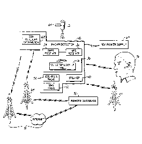
[00072] Fig. 3 illustrates a block diagram of the present invention in
operation in a particular
vehicle environment. The embodiment includes a radar detector 20, power supply
60, mobile
telephone 62, location sensing satellite 64, SWS communication network 66,
telephone
communication network 68, Internet communication network 70, and a remote
database 72. In this
embodiment the detector 20 obtains operational power through a power supply 60
connected by an
operable means, such as the SmartPlug which is used by the assignee of the
present invention.
However, operational power may be provided through on board means, such as a
rechargeable
battery. Operational power is described as the power required to allow the
detector to execute all
described functions.
[00073] In the embodiment of Fig. 3, the detector 20 has an operable
connection with a mobile
telephone 62. In this embodiment the mobile telephone 62 is enabled with IEEE
802.15.1
technology, also known as Bluetooth. While the operable connection between the
detector 20 and the
mobile telephone 62 may be in the form of a serial or USB cord, many cellular
telephones presently
available permit communication through the IEEE 802.X radio 54 of the detector
20. The detector 20
also incorporates a Safety Warning System radio 52 that allows the detector 20
to receive
informative messages regarding upcoming or ongoing road conditions.
[00074] During a radar detection alert in this embodiment, the detector 20
is able to obtain the
GPS coordinates of the detection, accomplished by communications between
satellites 64, beacons
(not shown), the DGPS receiver 34 and GPS receiver 32 of the detector 20. With
the coordinates
obtained by the receivers 32, 34, the detector 20 is able to determine whether
the detected signal can
be correlated with a signal detected in a previous radar detection encounter.
To correlate the present
signal detection with a previous detection encounter, the detector 20 compares
various parameters of
the current detection with the stored parameters of the previous detection.
Parameters that may be
evaluated are the signal signature of the present detected signal versus the
signal signature of a
previously detected signal within a predetermined area of the received
coordinates, the detector's rate
of travel at the time of the present detection versus the rate of travel at
the time of a previous
detection within a predetermined area of the received coordinates, the
direction of travel at the time
of the present detection versus the direction of travel at the time of a
previous detection within a
CA 3037278 2019-03-20
- 13 -
predetermined area of the received coordinates. These parameters are stored on
a detection look up
table 74 located on the EEPROM 36 of the detector 20.
[00075] Once a detection has been matched with a previous detection the
detector 20,
evaluates past user input during the previous detection when deciding whether
and how to alert
driver of the present detection. If the user has designated the matched
detection as a false alert, then
the detector 20 may mute the speaker 42 and/or forego a visual alert.
Alternatively, if the user has
designated the matched detection as an authentic detection, then the detector
20 may alert through
the speaker 42 and/or create a visual alert. Additionally, the detector may
send an audible alert to a
Bluetooth headset 76 through the IEEE 802.X radio 54. This feature is
especially useful in
environments where the user may have difficulty hearing an alert tone from the
detector's speaker 42
or would prefer a more personal in ear alert.
[00076] The operable connection with the mobile telephone 62 allows the
detector 20 to
communicate with a remote database 72. The remote database 72 stores
transmitted GPS coordinates
of an observed radar encounter or a detected radar encounter. An observed
radar encounter is a
situation when the user notices a speed trap, traffic camera, or other
mechanism designed for
purposes of ticket revenue or traffic deterrence instead of safety that may or
may not be emitting
radar. A speed trap may be defined as a location where the police strictly
enforce the speed limit.
Alternatively, a speed trap may be defined as a road section where police are
known to have a
reputation for writing an unusually high number of traffic tickets, the posted
speed limits are not
easily seen, or the speed limits are set much lower than a road engineering
survey may suggest.
[00077] The communication with the remote database 72 of the present
invention involves the
user operatively indicating to the detector 20 that the present detection
(observed or detected) is a
speed trap. This may be done with a switch, remote button, or by a button
located on the detector 20.
Once a user operatively characterizes a detection as a speed trap, the
detector 20 communicates with
the mobile telephone 62, which communicates particular parameters to the
remote database 72. The
communication between the mobile telephone 62 and the remote database 72 may
be accomplished
through a telephone communication network 68 such as a GSM or CDMA2000
protocol.
Communication through a telephone communication network 68 may be in the form
of a short
message through the short message service (SMS). The communication through the
telephone
communication network 68 may also be in the form of dual tone multi-frequency
(DTMF), also
known as touchtone. Where the mobile telephone 62 is capable of Internet
connectivity, the
communication between the mobile telephone 62 and the remote database 72 may
be accomplished
through an Internet communication 70. The mobile telephone 62 may obtain
Internet connectivity to
the remote database 72 through Internet communication 70 protocols such as
WiFi, Zigbee, EDGE,
or 3G.
CA 3037278 2019-03-20
- 14 -
[00078] The detector 20 may also receive notifications from the remote
database 72. These
notifications may communicate the location of speed traps that other detector
users have observed
and reported. By broadcasting the GPS coordinates through Internet
communication means 70 or
telephone communication means 68 in operable communication with the mobile
telephone 62 that is
in operable communication with the detector 20, the remote database 72 is able
to send information
to the detector 20. This information include the GPS coordinates of speed
traps indicated by other
detector users. This feature can provide real time speed trap notification to
detector users and alert
them to proceed with caution when a speed trap is approached.
[00079] The present invention also contemplates the use of non-GPS enabled
detectors. Fig. 3
illustrates a block diagram of an embodiment of the present invention where
the detector is an non-
GPS enabled detector 20. In this embodiment the power source attachment 78
houses a DGPS
receiver 80, a GPS receiver 82, a status display 84, and a detection look up
table 86. In this
embodiment the detector 20 may obtain operational power through the power
source attachment 78,
and operatively communicate with the power source attachment 78 regarding
previous and present
detections through a USB or serial cord connection or through IEEE 802.X radio
88.
[00080] Optionally, radar detector 20 may itself include an 802.x radio
permitting wireless
communication with power source attachment 78, in which case radar detector 20
may be battery
powered, or may be remotely located such as in the vehicle's grille area,
requiring only a 12 volt
power connection for complete installation.
[00081] As is done by circuits within the detector of Fig. 2, the power
source attachment 78
correlates stored data parameters of a present detection to the parameters of
a previous detection and
mutes the speaker 42 of the detector 20 and/or the visual alert accordingly.
The power source
attachment 78 is also equipped with a means of designating speed trap
locations. This may take the
form of a button or switch located on a keypad 89 of the power source
attachment 78. In this
embodiment, the power source attachment 78 is in operable communication with
the mobile
telephone 62, and with this configuration the user is still able to designate
speed traps and
communicate with the remote database 72 with similar communication means
described above. The
power source attachment 78 may also receive updated information regarding
speed trap locations
from the remote database 72 with similar communication means described above.
Also as noted
above, the power source attachment 78, or the detector 20 itself, can transmit
warnings to a
Bluetooth headset 76 through the IEEE 802.X radio 54.
[00082] Fig. 4 illustrates a block diagram of an embodiment of the present
invention where
there is no radar detector present. In this embodiment a button assembly 90
houses a DGPS receiver
92, GPS receiver 94, and an IEEE 802.X radio 96. The button assembly 90 is in
operative
communication with a power supply 60, and a mobile telephone 62. The
communication between the
CA 3037278 2019-03-20
- 15 -
button assembly 90 and the mobile telephone 62 may be made either by a serial
or USB connection
or through the IEEE 802.X radio 62.
[00083] In the embodiment of Fig. 4, the toggle button assembly 90
includes a GPS receiver
94 and DGPS receiver 92 for detecting a current location, and interacts via an
IEEE 802.x radio with
a cellular telephone 62 or other communication device to retrieve speed trap
locations from a remote
database 72. This communication may be by the telephone communication network
68, or the
Internet communication network 70 by the means described above. Nearby speed
traps which have
been identified in the database are acquired and if the vehicle approaches one
of those speed traps, a
warning is delivered via the cellular telephone 62 or via a display and/or
speaker which may be
included in the toggle button assembly 90.
[00084] Furthermore, when a user of the embodiment of Fig. 4 visually
detects a speed trap,
the user may activate the button assembly 90, by toggling a button, switch, or
knob. Once activated
the button assembly will document the GPS coordinates received by the DGPS and
GPS receivers
92, 94 that communicate with the location sensing satellite 64, and then
operatively communicate the
information to the mobile telephone 62. The mobile telephone 62 may then
transmit the coordinates
of the detection to the remote database 72. Subsequently, other travelers may
receive Internet
messaging, or retrieve an update from database 72, including the annotation of
the speed trap, and
deliver the appropriate warnings.
[00085] Fig. 5 illustrates, for comparison, a block diagram of an
embodiment of a speed trap
detection system that utilizes a mobile phone. Recently a system of this kind
has been marked at the
URL www.trapster.com. In this application, a user reports the detection of a
speed trap through an
application on a GPS enabled mobile telephone 98 by pressing a programmed
button on the phone
98. Button activation will cause the phone 98 to document the GPS coordinates
received from a
locating satellite 64, and send the received coordinates of the indicated
speed trap to the remote
database 72 by a telephone communication network 68, or via an Internet
communication network
70. Subsequently, the application on the GPS enabled mobile telephone may
retrieve locations of
speed traps stored in remote database 72 and deliver responsive alerts to the
user of the phone. This
embodiment requires the use of a GPS enabled mobile telephone, a customized
application on that
telephone, and the constant operation of that application on the telephone,
none of which are required
in the embodiment of Fig. 4, making Fig. 4 more usable for many environments
which are not
available in Fig. 5.
[00086] Fig. 6 illustrates a block diagram of an embodiment of the present
invention where the
detector 20 is in operable communication with a GPS unit 100. In this
embodiment the detector 20
and GPS unit 100 may communicate through a serial or USB connection, or
through IEEE 802.X
radios 54, 102. When the detector 20 detects radar, it will access the
coordinates provided by the
CA 3037278 2019-03-20
- 16 -
GPS unit 100 that is in operable communication with a location sensing
satellite 64, and determine
whether the detected signal can be correlated with a signal detected in a
previous radar detection
encounter. Accessing the detector look up table 74 located on the EEPROM 36
and correlating of the
present signal with a previous detection encounter as described above.
Additionally, whether and
how the detector 20 alerts through the speaker 42 is described above. The
detector 20 in this
embodiment is in operative communication with a mobile telephone 62 either by
a serial or USB
connection or through the IEEE 802.X radio 54. Through this connection the
invention is able to
operatively communicate with the remote database 72 by a telephone
communication network 68 or
an Internet communication network 70 through the method described above. The
detector 20 in this
embodiment is also able to receive speed trap location updates from the remote
database 72. The
detector 20 may send an audible alert to a Bluetooth headset 76 through the
IEEE 802.X radio 54.
[00087] Fig. 7 illustrates a block diagram of an embodiment of the present
invention where the
detector 20 is in operable communication with a power supply 60 and a
navigation unit 110. In this
embodiment the detector 20 is in operative communication with a navigational
unit 110 through a
serial or USB connection, or through IEEE 802.X radios 54, 112. When the
detector 20 detects radar,
it will access the coordinates provided by the navigational unit 110 that is
in operable
communication with satellites 64 and determine whether the detected signal can
be correlated with a
signal detected in a previous radar detection encounter. The detector 20 then
accesses the detector
look up table 74 located on the EEPROM 36 and correlating of the present
signal with any previous
detection encounter as described above, and determines whether and how to
alert through the speaker
42 as described above. The detector 20 may send an audible alert to a
Bluetooth headset 76 through
the IEEE 802.X radio 54.
[00088] Referring now to Fig. 8A, in an alternative embodiment the
invention may be
implemented as a substitute power cord assembly for a radar detector. In this
embodiment the power
cord assembly includes a GPS receiver, DGPS receiver and marked detection
lookup table or map.
The power cord assembly is coupled to a conventional radar detector to provide
power to the detector
and to provide a mute signal to the detector. It will be appreciated that the
power cord used with
many conventional radar detectors includes a signal line for a mute signal,
which is activated by a
pushbutton on the power cord assembly. The power cord assembly of Fig. 8A
connects to this mute
signal line and provides a mute signal to the detector in the event that the
location of the detector, as
determined by the GPS receiver in the power cord assembly, correlates to a
rejectible signal as
identified in the lookup table in the power cord assembly. The database in the
power cord assembly
may be updated in the event that the user mutes an alert of a radar signal
being generated by the radar
detector, e.g., the power cord assembly may provide the user the option to
store the location where
the mute was engaged, to prevent future alerts at the same or a similar
location.
CA 3037278 2019-03-20
- 17 -
[00089] The embodiment of Fig. 8A may be further implemented through a
firmware upgrade
to a conventional radar detector. New firmware in the detector may cause the
detector to differently
condition its alerts upon responses from the power connector, so that the GPS
receiver in the power
cord is more tightly coupled to the radar detector and more tightly controls
the alerts from the GPS
receiver in a manner more directly akin to an integrated unit.
[00090] Figs. 8B 1 and 8B2 illustrate an embodiment of the invention in
which an integrated
vehicle navigation unit that includes GPS receivers, a display and a map
function, communicates
with a radar detector. The connection to the radar detector may be wired as
shown in Fig. 8B1 or
wireless via a Bluetooth or other 802.x radio as shown in 8B2. In either case,
an application in the
navigation unit operates to generate alerts of radar when detected by the
attached radar detector, and
further communicates with a stored lookup table or map to suppress radar
warnings in the event that
a detected signal correlates to a rejectable signal, and to store false signal
locations when identified
by the user via the user interface of the navigation unit.
[00091] Figs. 8C1 and 8C2 illustrates an embodiment similar to Figs. 8B1
and 8B2 in which a
dashboard GPS receiver, which includes GPS receivers, a display and a map
function, communicates
with a radar detector. Here again, the connection to the radar detector may be
wired as shown in Fig.
8C1 or wireless via a Bluetooth or other 802.x radio as shown in 8C2. In
either case, an application
in the GPS unit generate alerts of radar when detected by the attached radar
detector, and further
communicates with a stored lookup table or map to suppress radar warnings in
the event that a
detected signal correlates to a rejectable signal, and to store false signal
locations when identified by
the user via the user interface of the GPS unit.
[00092] Fig. 8D illustrates an alternative embodiment of the invention in
which a 12 volt
power source attachment including GPS and DGPS receivers and a display, is
coupled via a
Bluetooth or other 802.x radio to a remote radar detector that includes
Bluetooth functionality but
does not include GPS functionality. One example of such a device is the radar
detection unit sold by
K40 Electronics under the brand name Calibre. In this embodiment, the power
cord assembly
communicates via Bluetooth or another 802.x wireless communication standard
with the remote
radar detector to acquire information about radar warnings, and the power cord
assembly generates
warnings on the display of the power source attachment. Further, the power
source attachment
communicates with a stored lookup table or map to suppress radar warnings in
the event that a
detected signal correlates to a rejectable signal, and may include a user
interface such as a mute
button, usable to store false signal locations when identified by the user via
that user interface.
[00093] Turning now to Figs. 9-15, as many of these figures include items
already discussed
hereinabove in connection with Figs. 1-8D, these discussions will not be
repeated but are applicable
to Figs. 9-15 as well. In the embodiment of Fig. 9, the detector 20 includes a
GSM cellular data
CA 3037278 2019-03-20
- 18 -
modem 200 embedded within the detector 20 for both receiving and transmitting
data, instead of an
operable connection with an external mobile telephone (e.g., mobile 62
discussed in connection with
Fig. 3) for receiving and transmitting data.
[00094] Those of ordinary skill in the art may appreciate that by
embedding the modem 200 in
the detector 20, data may be continuously transmitted from the radar detector
to a server, analyzed at
the server, and pooled into a master remote database on the server. In turn,
the radar detector may
receive pertinent updated data on coordinates, designations of coordinates
(e.g., as a threat or false
alert), software updates, among other data, from the remote database on the
server, all in real-time,
and potentially without any human interaction after the initial installation
of the radar detector in the
vehicle.
[00095] Indeed, the detector 20 may be able to receive real-time data
about false alerts and
threats without having to utilize the mobile 62 to connect the detector 20 to
the server, without
having to physically connect the mobile 62 to the detector 20, without having
to ensure the mobile 62
is charged and operational, without having to deal with cables to connect the
mobile 62 to the
detector 20, without connecting the detector 20 (or part thereof) to any other
device for data (e.g.,
software updates, data on false alert, data on threats), etc. For example, in
Europe, users generally
have to plug their detectors to a computer via USB to find retrieve data on
the threats (e.g., data on
the cameras that are on for that day), but such user intervention may be
avoided or greatly reduced
by the embodiments discussed herein. Furthermore, a large database at the
detector 20, with data
that is not updated (i.e., stale), may be avoided or at least minimized as a
much smaller database
and/or storage may be maintained at detector 20 with the updated data received
in real-time.
Moreover, the detector 20 may be updated with data that is more pertinent to
the driver such as data
about speed traps or false alarms or alerts within a certain radius of the
detector 20 as these are
positions the user is more likely to encounter then speed traps or false
alerts five states away.
Indeed, it may not be productive to store data for every door opener in the
country as the driver will
likely not be encountering such distant openers.
[00096] Turning first to the GSM cellular data modem 200 of Fig. 9,
although a GSM type of
cellular data modem is utilized as the modem 200, such need not be the case in
other embodiments.
For example, a different type modem may be utilized such as a different type
of cellular data modem
or bi-directional paging or any other bi-directional communications device.
However, it may be
beneficial to use a GSM type of cellular data modem because GSM, which stands
for Global System
for Mobile communications, is an international standard and a GSM cellular
data modem will
typically work anywhere where the GSM standard is supported (e.g., with minor
adjustments such as
switching a Subscriber Identity Module (hereinafter "SIM") card). However, as
will be discussed
further below in connection with the Jasper Wireless list, not all GSM
cellular data modems in the
CA 3037278 2019-03-20
- 19 -
United States function outside of the United States (e.g., due to GSM
operating at different MHz in
different countries). Thus, the GSM cellular data modem 200 in the detector 20
should be selected
so as to function in the country where the radar detector 20 will be utilized
(e.g., in the United
States). Further, the detector 20 may have more than one GSM cellular data
modem in some
embodiments, for example, to account for these differences.
[00097] As illustrated in Fig. 9, the GSM cellular data modem 200 is
coupled to the processor
22. The processor 22 generally controls all functions of the detector 20,
including controlling all the
functions of the modem 200 such as controlling the modem 200 to receive and/or
transmit data.
Under control of the processor 22, the modem 200 receives and transmits data,
and the processor 22
may process the data received by the modem 200 and the processor 22 may
provide data to the
modem 200 for transmission. Indeed, incoming and outgoing arrows are
illustrated in Fig. 9 between
the modem 200 and the processor 22 to emphasize that the detector 20 is
capable of two way
communication such that the detector 20 may receive data through the modem
2(X) for the processor
22 (e.g., to store the data in the flash memory of the flash memory slot 50 or
even in the EEPROM
36) and/or may transmit data of the processor 22 through the modem 200 (e.g.,
to the remote
database 72 illustrated in Figs. 10-12). The two way communication capability
will be discussed
further in connection with Fig. 10.
[00098] The processor 22 may be implemented in hardware using circuit logic
disposed on
one or more physical integrated circuit devices (e.g., one or more circuit
boards), or chips. Although
the processor 22 is illustrated as a single processor, the processor 22 may be
a plurality of processors.
If the fusion processor 22 is a plurality of processors, the modem 200 may be
coupled, for example,
to each of the processors in the plurality of processors.
[00099] Like a mobile telephone, the modem 200 may include a SIM card (not
shown) with
the user's subscription information and may even have a cellular phone number
associated with it.
The SIM card is a small removable disk that slips in and out of the GSM
cellular data modem 200
and may include all the connection data and identification numbers for
accessing a particular
wireless service provider, such as AT&T Inc. (hereinafter "AT&T'). The modem
200 may also have
a circuit-switched data (CSD) service from a wireless service provider, such
as AT&T, associated
with it.
[000100] The modem 200 may be from the list of certified modules and
certified integrated
devices at the website of Jasper Wireless, Inc. (hereinafter "Jasper
Wireless") at
www.jasperwireless.com. Jasper Wireless has the following contact information
for its U.S. office:
Jasper Wireless, Inc., 501 Macara Avenue, Suite 202, Sunnyvale, CA 94085, Tel:
+1 408 328 5200,
Fax: +1 408-328-5201. Jasper Wireless has the following contact information
for its European
office: Jasper Wireless, Ltd., 176 St Vincent Street, Glasgow G2 5SG, United
Kingdom, Tel: +44 (0)
CA 3037278 2019-03-20
- 20 -
141 249 6780, Fax: +44 (0) 141 249 6700. The certified modules on the Jasper
Wireless list, for
example, may include a modem and are deployed on the Jasper Wireless Platform.
Thus, the modem
200 may be a standalone modem, part of a module, part of a modified module, a
device, part of a
device, part of modified, etc., for example, from the Jasper Wireless list of
certified modules and
certified devices but need not be from the Jasper Wireless list of certified
modules and certified
devices. Those of ordinary skill in the art may appreciate that use of a
certified module and/or
certified device from the Jasper Wireless list, for example, may lead to
speedier implementation of
the detector 20 of Figs. 9-15.
[000101] Specifically, for deployment in the United States, Jasper Wireless
requires that
modules be AT&T certified, and the Jasper Wireless list includes a variety of
AT&T certified
modules for deployment on the Jasper Wireless Platform, including Enfora
GSM0104, GSM0108,
GSM0113, GSM0204, GSM0208, GSM0304, GSM0308, and GSM0404. The list also
includes
certified modules of Cinterion, Ericsson, Motorola, Novatel, Option,
Qualcornm, Sierra Wireless,
Telit, and Wavecom. Jasper Wireless also has additional modules that it has
certified for deployment
outside of the United States, including modules of Cinterion (Siemens), Enfora
(e.g., G5M2218 and
GSM 1218), Sony Ericsson, Ericsson, Sagem, SIMCom, Telit, Wavecom, and iWow.
The list also
includes integrated devices certified for the Jasper Wireless Platform,
including integrated devices of
CalAMP, Dejavoo, Digital Communications Technologies, Enfora, Fakom USA,
Gemalto,
Hypercom, Ingenico / Sagem, MultiTech, Noval, NovaTracker, Prolificx, Janus
RemoteCommunications, Scope Logistical Solution, TechTrex, Trimble, Wavecom,
and VeriFone.
See hitu://www.jasperwireless.corn/platform/certified-devices.html.
[000102] Also, u-blox America, Inc. (hereinafter "u-blox"), at www.u-
blox.cont, may be
contacted for hardware for development. According to its website, u-blox is a
fabless semiconductor
provider of embedded positioning and wireless communication solutions for the
consumer, industrial
and automotive markets that enables people, devices, vehicles and machines to
locate their exact
position and wirelessly communicate via voice, text or video. The following is
the contact
information for the head U.S. office: u-blox America, Inc., 1902 Campus
Commons Drive Suite 310,
Reston, VA 20191, USA, info us@u-blox.com, Phone +1 (703) 483 3180, Fax
+1(703) 483 3179.
U-blox has other locations around the world.
[000103] Data suppliers that may be contacted include AT&T and Juniper
Networks. AT&T,
at http://www.att.comt, has the following as the contact information for its
headquarters: AT&T Inc.,
175 E. Houston St., San Antonio, TX 78205. At&T has other locations around the
world. Juniper
Networks, at http://www.juniper.netlusien/, has the following as the contact
information for its
headquarters: 1194 North Mathilda Avenue, Sunnyvale, California 94089-1206
USA, Phone: 888-
CA 3037278 2019-03-20
-21 _
JUNIPER (888-586-4737), 408-745-2000, Fax: 408-745-2100. Juniper Networks has
other locations
around the world.
[000104] Thus, the modem 200 of the detector 20 of the embodiment of Fig. 9
may be a
certified module (or modification thereof) from the Jasper Wireless list that
is added to the circuit
board or chip of the processor 22 for deployment on the Jasper Wireless
Platform, or the hardware
may be obtained from u-blox, and AT&T or Juniper may serve as the wireless
service provider for
the transmitting and providing data to the GSM system using GSM technology.
However, those of
ordinary skill in the art will appreciate that there may be other ways of
implementing the detector 20
with the embedded modem 200. Indeed, u-blox also has a portfolio of GPS
modules, cards, chips,
and software solutions together with wireless modules and solutions, thus,
those of ordinary skill in
the art may appreciate that a module of u-blox (or modification thereof) or a
module (or modification
thereof) of some other provider, for example, may be utilized for the modem
200 instead of the
certified modules from the Jasper Wireless list.
[000105] Turning to Fig. 10, this figure illustrates a block diagram of the
detector 20 of Fig. 9
in a vehicle environment. Although only a single radar detector 20 is shown
for simplicity in these
and other figures, those of ordinary skill in the art will appreciate that
multiple radar detectors 20 will
generally be present in the environment. Specifically, the detector 20
includes the GSM cellular data
modem 200 embedded within the detector 20 for both receiving and/or
transmitting data to the
remote database 72 through a communication network such as the telephone
communication network
68 (e.g., GSM or CDMA2000 protocol) and/or the Internet communication network
70 (e.g., WiFi,
Zigbec, EDGE, or 3G). EDGE refers to Enhanced Data rates for GSM Evolution
technology,
providing enhancements to GSM networks, and may use the same structure as GSM
networks. As
such, this may allow EDGE to be overlaid directly onto an existing GSM network
(e.g., via a
software-upgrade). The remote database 72 may be located at a server such as
server 300 (Fig. 11).
The detector 20 via the modem 200 is capable of direct real-time two way
communication through
the telephone communication network 68 and/or Internet communication network
70 with server
300, which contains the remote database 72. The detector 20 or various
detectors 20 and the server
300 may be considered a system, and will be discussed further in connection
with Fig. 11.
[000106] Specifically, the detector 20 includes the modem 200 embedded
within the detector
20 for directly receiving and transmitting data, instead of an operable
connection with an external
mobile telephone 68 for receiving and transmitting the data (illustrated in
Fig. 2 and Fig. 3). The
modem 200 is capable of direct two way communication in a real-time manner
through the telephone
communication network 68 and/or Internet communication network 70 with the
remote database 72
at the server 300. Although the term real-time is being utilized for
simplicity, real-time also may
include near real time, which refers to the slight delay that may be
introduced by automated data
CA 3037278 2019-03-20
- 22 -
processing and/or network transmission between when an event occurs and use of
the processed data
for display and control purposes.
[000107] As the modem 200 embedded within the detector 20 is replacing the
external mobile
telephone 68 that was connected to the detector 20, the modem 200 performs
some or all of the
functions of the mobile telephone 68. For example, the modern 200 may be
responsible for
converting digital data into radio signals for outgoing communication and/or
converting radio signals
to digital signals for incoming communication. Thus, receiving and
transmitting data by the modem
200 may require conversions. To that end, the modem 200 may include a DSP (not
shown) such as
DSP 26, discussed in connection with Fig. 2 and Fig. 3, to carry out the
conversions. Alternatively,
the conversions rnay be performed elsewhere in the detector 20, for example,
the modem 200, under
control of the processor 22 (Fig. 9) may relay radio signals it receives to
the DSP 26 to carry out the
conversions. The modem 200 may also include an antenna (not shown) for
receiving and
transmitting data.
[000108] The remote database 72 at the server 300 may store transmitted GPS
coordinates of an
observed radar encounter or a detected radar encounter such as a speed trap
transmitted by the
detector 20 or other detector. As discussed above in connection with Fig. 3,
an observed radar
encounter is a situation when the user notices a speed trap, traffic camera,
or other mechanism
designed for purposes of ticket revenue or traffic deterrence instead of
safety that may or may not be
emitting radar. A speed trap may be defined as a location where the police
enforce the speed limit.
Alternatively, a speed trap may be defined as a road section where police have
a reputation for
writing an unusually high number of traffic tickets, the posted speed limits
are not easily seen, or the
speed limits are set much lower than a road engineering survey may suggest.
For simplicity, these
will be referred to as threats or threat designations if a user designates
them as threats. On the other
hand, door openers or other sources that might falsely trigger an alert will
be referred to a false alerts
or false alert designations if the user designates them as false alerts.
[000109] Turning to Fig. 11, Fig. 11 may be thought of as illustrative of a
client-server system
or environment. The client-server system or environment may include at least
one client (e.g., the
detector 20 may be considered a client as well as any other detectors that
communicate with the
server computer 300) and at least one server (e.g., the server computer 300).
The system includes at
least one apparatus, e.g., one or more clients in the form of the detector 20
and one or more servers in
the form of the server computer 300. The computer 300 may represent
practically any type of
computer, computer system or other programmable electronic device capable of
functioning as a
server in a client-server environment. For example, in specific embodiments,
the computer 300 may
be a computer, computer system, computing device, disk array, or programmable
device such as a
multi-user computer, a single-user computer, a handheld device, a networked
device (including a
CA 3037278 2019-03-20
- 23 -
computer in a cluster configuration), a mobile phone, a video game console (or
other gaming
system), etc. Moreover, the computer 300 may be implemented using one or more
networked
computers, e.g., in a cluster or other distributed computing system. Further,
as is common in many
client-server systems, typically multiple clients (i.e., multiple detectors
20) will be interfaced with
the server computer 300. However, given the nature of computer 300 as a
server, in many instances
computer 300 may be implemented using a multi-user computer such as a server
computer, a
midrange computer, a mainframe, etc. As a result, the specifications of the
CPU's, memories, mass
storage, user interfaces and network interfaces may vary between the computer
300 and the detector
20 to accommodate the possibly higher demands on the computer 300. Other
hardware
environments are contemplated within the context of the invention.
[000110] Computer 300 typically includes a central processing unit (CPU)
326 including at
least one microprocessor coupled to a memory 328, which may represent the
random access memory
(RAM) devices comprising the main storage of computer 300, as well as any
supplemental levels of
memory, e.g., cache memories, non-volatile or backup memories (e.g.,
programmable or flash
memories), read-only memories, etc. The remote database 72 may be resident in
the memory 328.
The CPU 326 is typically implemented in hardware using circuit logic disposed
on one or more
physical integrated circuit devices, or chips. Thus, the computer 300 may
include at least one
hardware-based processor. The CPU 326 may be one or more microprocessors,
micro-controllers,
field programmable gate arrays, or ASICs, while memory 328 may include random
access memory
(RAM), dynamic random access memory (DRAM), static random access memory
(SRAM), flash
memory, and/or another digital storage medium, typically implemented using
circuit logic disposed
on one or more physical integrated circuit devices, or chips. As such, the
memory 328 may be
considered to include memory storage physically located elsewhere in the
computer 300, e.g., any
cache memory in a processor in the CPU 326, as well as any storage capacity
used as a virtual
memory, e.g., as stored on a mass storage device 330 or on another computer
coupled to the
computer 300. The computer 300 also typically receives a number of inputs and
outputs for
communicating information externally. For interface with a user or operator,
computer 300 typically
includes a user interface 332 incorporating one or more user input devices
(e.g., a keyboard, a
mouse, a trackball, a joystick, a touchpad, and/or a microphone, among others)
and a display (e.g., a
CRT monitor, an LCD display panel, and/or a speaker, among others). Otherwise,
user input may be
received via another computer or terminal or from the modem 200 of the
detector 20. Likewise, the
computer 300 may output data and transmit it to the modem 200 of the detector
20.
[000111] For additional storage, the computer 300 may also include one or
more mass storage
devices 330, e.g., a floppy or other removable disk drive, a hard disk drive,
a direct access storage
device (DASD), an optical drive (e.g., a CD drive, a DVD drive, etc.), and/or
a tape drive, among
CA 3037278 2019-03-20
- 24 -
others. Furthermore, the computer 300 may include an interface 334 with one or
more networks
(e.g., a LAN, a WAN, a wireless network, the Internet (e.g., the Internet
communication network
70), WiFi, Zigbee, EDGE, or 3G, a cellular or telephone network (e.g., the
telephone communication
network 68), GSM and/or CDMA2000 protocol, among others) to permit the
communication of
information with other computers, electronic devices, the radar detector 20,
multiple radar detectors
20, etc. Communication through the telephone communication network 68 may be
in the form of a
short message through the short message service (SMS). The communication
through the telephone
communication network 68 may also be in the form of dual tone multi-frequency
(DTMF), also
known as touchtone. Indeed, the interface 334 may interface with a network
that may be public
and/or private, wireless and/or wired in some aspect, local and/or wide-area,
represent multiple
interconnected networks, etc. It should be appreciated that the computer 300
typically includes
suitable analog and/or digital interfaces between the CPU 326 and each of the
components 328, 330,
332 and 334 as is well known in the art.
[000112] The computer 300 operates under the control of an operating system
340, and
executes or otherwise relies upon various computer software applications,
components, programs,
objects, modules, data structures, etc. (e.g. server 344). Moreover, various
applications, components,
programs, objects, modules, etc. may also execute on one or more processors in
another computer
coupled to computer 300 via a network, e.g., in a distributed or client-server
computing environment,
whereby the processing required to implement the functions of a computer
program may be allocated
to multiple computers over a network.
[000113] In general, the routines executed to implement the embodiments of
the invention,
whether implemented as part of an operating system or a specific application,
component, program,
object, module or sequence of instructions, or even a subset thereof, will be
referred to herein as
"computer program code," or simply "program code." Program code typically
comprises one or
more instructions that are resident at various times in various memory and
storage devices in a
computer, and that, when read and executed by one or more processors in a
computer, cause that
computer to perform the steps necessary to execute steps or elements embodying
the various aspects
of the invention. Moreover, while the invention has and hereinafter will be
described in the context
of fully functioning computers and computer systems, those skilled in the art
will appreciate that the
various embodiments of the invention are capable of being distributed as a
program product in a
variety of forms, and that the invention applies equally regardless of the
particular type of computer
readable signal bearing media used to actually carry out the distribution.
Examples of computer
readable signal bearing media include but are not limited to physical and
tangible recordable type
media such as volatile and non-volatile memory devices, floppy and other
removable disks, hard disk
CA 3037278 2019-03-20
- 25 -
drives, magnetic tape, optical disks (e.g., CD-ROMs, DVDs, etc.), among
others, and transmission
type media such as digital and analog communication links.
[000114] In
addition, various program code described hereinafter may be identified based
upon
the application within which it is implemented in a specific embodiment of the
invention. However,
it should be appreciated that any particular program nomenclature that is used
herein is merely for
convenience, and thus the invention should not be limited to use solely in any
specific application
identified and/or implied by such nomenclature. Furthermore, given the
typically endless number of
manners in which computer programs may be organized into routines, procedures,
methods,
modules, objects, and the like, as well as the various manners in which
program functionality may be
allocated among various software layers that are resident within a typical
computer (e.g., operating
systems, libraries, API's, applications, applets, etc.), it should be
appreciated that the invention is not
limited to the specific organization and allocation of program functionality
described herein.
[000115]
Furthermore, the server computer 300 may be a web server computer, such as the
web
server computer 400 of Fig. 12, or some other type of server computer. Turning
to Fig. 12, in a
similar manner to the computer 300, the web server computer 400 of Fig. 12 may
include CPU 326,
memory 328, mass storage 330, user interface 332, network interface 334,
operating system 340, and
the remote database 72 as discussed in connection with the computer 300 of
Fig. 11. For example,
the CPU 326 of the web server computer 400 may likewise include at least one
hardware-based
processor, with the CPU 326 is implemented in hardware using circuit logic
disposed on one or more
physical integrated circuit devices, or chips. Indeed, the CPU 326 of the web
server computer 400
may be one or more microprocessors, micro-controllers, field programmable gate
arrays, or ASICs,
while the memory 328 of the web server computer 400 may include random access
memory (RAM),
dynamic random access memory (DRAM), static random access memory (SRAM), flash
memory,
and/or another digital storage medium, typically implemented using circuit
logic disposed on one or
more physical integrated circuit devices, or chips. Similarly, the remote
database 72 may be resident
in the memory 328 of the web server computer 400. Furthermore, the web server
computer 400
operates under the control of the operating system 340, and executes or
otherwise relies upon various
computer software applications, components, programs, objects, modules, data
structures, etc. (e.g.
web server 444).
[000116] In general, the discussion hereinabove for computer 300 (Fig. 11)
is applicable to the
discussion of the web server computer 400, with the main difference being that
the web server 444
replaces the server computer 400 to provide web-based connections. The server
344 and the web
server 444 may generally be considered to include any program code resident on
a computer or other
programmable electronic device that is capable of servicing requests and/or
analysis in a distributed
computer system. Additionally, the server 344 and web server 444 may be
considered to include the
CA 3037278 2019-03-20
- 26 -
hardware associated with each (e.g., the computer 300 and the server computer
400, respectively) as
well as the software (e.g., program code).
[000117] Additionally, with the web server computer 400, the network
interface 334 of the web
server computer 400 may be more likely to interface with the Internet
communication network 70
instead of the telephone communication network 68. As such, the telephone
communication network
68 is illustrated in phantom. However, there may be some embodiments where the
network interface
334 of the web server computer 400 may still interface with both the Internet
communication
network 70 and the telephone communication network 68 as illustrated in Fig.
11, or simply interface
with the telephone communication network 68.
[000118] Those skilled in the art will recognize that the exemplary
environments illustrated in
Figs. 10-12 are not intended to limit the present invention. Indeed, those
skilled in the art will
recognize that other alternative hardware and/or software environments may be
used without
departing from the scope of the invention. For example, although a web server
44 is utilized herein,
those of ordinary skill in the art will appreciate that another server and/or
server computer may be
utilized. Furthermore, although only a single radar detector 20 is shown for
simplicity in these
figures, those of ordinary skill in the art will appreciate that multiple
radar detectors 20 may
communicate with the server 300 and/or the web server 400, and that the server
300 and/or the web
server 400 may communicate with multiple radar detectors 20.
[000119] In the
context of the embodiments discussed hereinabove, the communication
between the detector 20, with the embedded modem 200, and the remote database
72 of the server
computer 300 and/or the web server computer 400 involves the user operatively
indicating to the
detector 20 that the present detection (observed or detected) should be
designated as a false alert or
as a threat. This may be done with a switch, remote button, or by a button
located on the detector 20.
Once the user operatively designates a detection as a false alert, for
example, under control of the
processor 22, the modem 200 of the detector 20 may communicate in real-time
the particular
parameters of the false alert, such as the coordinates of the false alert and
data related to the
coordinates such as an indication of the false alert designation, to the
server computer 300 and/or the
web server computer 400 to the remote database 72. The detector 20 is able to
obtain the GPS
coordinates of the detection by communications between satellites 64, beacons
(not shown), the
DGPS receiver 34 and GPS receiver 32 of the detector 20. The communication
between the modem
200 and the remote database 72 may be accomplished through the telephone
communication network
68 such as a GSM or CDMA2000 protocol 72 and/or accomplished through the
Internet
communication 70 through WiFi, Zigbee, EDGE, or 3G.
[000120] The server
computer 300 and/or the web server computer 400 may analyze the
received parameters from the detector 20 (and other detectors) in real-time
(e.g., at the CPU 326), for
CA 3037278 2019-03-20
_27 _
example, to determine if the false alert designation at the coordinates
received from the dectector 20
has been received a sufficient number of times (e.g., via a counter saved in
the remote database 72)
from different radar detectors 20. If so, the server computer 300 and/or the
web server computer 400
transmits a notification (e.g., transmitting the coordinates and perhaps an
indication of the false alert
designation and/or data that would mute and/or forgo alerting at the
coordinates of the false alert
designation) to all the radar detectors within a radius, where the coordinates
of the false alert fall
within that radius. Alternatively, it may transmit to those that have not
designated these coordinates
as a false alert within the radius. Likewise, a threat designation may be
performed in a similar
manner, with the server computer 300 and/or the web server computer 400
transmitting the
coordinates and may also data related to the coordinates such as an indication
of the threat
designation. Furthermore, an indication about whether the coordinates of the
location of the detector
20, the heading, and /or the speed may also be transmitted.
[000121] Regarding the radius, each radar detector may continuously
transmit to the server
computer 300 and/or the web server computer 400 its location (e.g., GPS
coordinates), heading,
and/or speed data for storage in the remote database 72, and the server
computer 300 and/or the web
server computer 400 may determine which radar detectors are within the radius
based on the
continuously received data. Regarding the remote database 72, it may serve as
a master database or
repository for aggregating data received from multiple radar detectors, and
may include, for example,
false alert designations, coordinates of false alert designations, threat
designations, coordinates of
threat designations, location data, including GPS coordinates, of the radar
detector, heading data of
the radar detector, speed data of the radar detector, counters, etc. for
analysis by the server computer
300 and/or the web server computer 400 such as by the CPU 326 thereof, for
example, for comparing
counters to a threshold, determining radar detectors within in a radius, etc.
The indications of the
designations may be transmitted by either the detector 20 and/or the server
300 and/or computer 400
to reduce inaccuracies and confusion regarding why specific coordinates are
being transmitted.
[000122] Thus, the detector 20 may not only transmit information to the
server 300 and/or the
web server 400, but it may also receive data at the embedded modem 200 from
the server computer
300 and/or the web server computer 400 from the remote database 72. This data
may communicate the location of false alerts or speed traps and/or threats
that other detector users
have observed and reported. By broadcasting the GPS coordinates through
Internet communication
network 70 and/or telephone communication network 68 to the modem 200 of the
detector 20, the
server computer 300 and/or the web server computer 400 containing the remote
database 72 is able
to send information to the detector 20 and others within the radius. This
information may include the
GPS coordinates of false alert designations and/or threat designations
indicated by other detector
users such that the information that is more pertinent to a driver is received
at their corresponding
CA 3037278 2019-03-20
- 28 -
detector. This feature can provide real time data to detector users and alert
them to proceed with
ease or proceed with caution. Similarly, the server computer 300 and/or the
web server computer
400 may transmit software updates to the radar detectors.
[000123] All of the receive information by the modem of the radar detector
20 may be stored in
the flash memory of slot 50 (Fig. 9) or even in the EEPROM 36 (Fig. 9) of the
detector.
Furthermore, those of ordinary skill in the art may appreciate that as real-
time pertinent data will be
received from the server computer 300 and/or the web server computer 400, the
storage of the
detector 20 may be smaller, instead of a larger storage that has out of date
or stale data, and smaller
storage may lead to reduction in cost and/or allow for faster searches of the
storage and improve the
reaction time of the detector 20. Although the inclusion of an embedded modem
200 within the
detector 20 may increase the cost of the detector 20, the modem 200 may in
turn lead to smaller data
storage requirements.
[000124] Furthermore, it is worth noting that the radar detector 20 may
also perform other tasks
discussed in connection with Figs. 1-8D such as using the coordinates of a
detected signal obtained
by the receivers 32, 34, the detector 20 is able to determine whether the
detected signal can be
correlated with a signal detected in a previous radar detection encounter. But
as described herein, the
radar detector 20 may further determine if data was received from the server
300 and/or the web
server 400 regarding the coordinates of this detected signal and the whether a
warning or alert should
or should not be issued by the detector 20 via the processor 22 (Fig. 9). As
such, the detector 20 and
the server 300 and/or the web server 400 may be in real-time communication
with each other
receiving and transmitting information, without human intervention (e.g.,
except for the potential
intervention by a user designating a false alert or a threat), that may
improve accuracy and improve
the experience of the user.
[000125] Turning now to Fig. 13, this figure illustrates an exemplary false
alert designation
routine 501 with a plurality of radar detectors 500, 502, 504, 506, with each
similar to the radar
detector 20, and with each having an embedded modem such as the modem 200
illustrated in Figs. 9-
12. These detectors may be in real-time two communication with server computer
514, which is
similar to the server computer 300 and/or the web server computer 400. For
ease of understanding, a
step of the routine 501 (or a step of the other routines 601 and 701 in Figs.
14-15) illustrated in the
radar detectors 500, 502, 504, 506 or in the server computer 514 is meant to
indicate that the step
may be performed in that item. Although only four radar detectors are
illustrated for simplicity,
those of ordinary skill in the art will appreciate that many more detectors
may be in real-time two
way communication with the server computer 514.
[000126] Starting with block 508 in the detector 500, the detector 500 may
alert the user of a
detected signal. For example, the detector 500 may not have any other
information on the
CA 3037278 2019-03-20
- 29 -
coordinates of the detected signal or this may be the first time any of the
detectors in communication
with the server computer 514, including detector 500, have detected a signal
at these coordinates, and
' as such, the detector 500 alerts the user of the detected signal. If the
user learns that the detected
signal is a false alert, the user may give it a false alert designation by
muting the alert at block 510,
and an indication of the false alert designation and the coordinates may be
transmitted automatically
to the server computer 514 at block 512. It is worth noting that it may be
advantageous to transmit
both the coordinates of the false alert designation as well as the false alert
designation indication to
reduce inaccuracies among all the coordinates that will be transmitted from
the various detectors at
various times to the server computer 514. However, in some embodiments, the
false alert
designation indication may be omitted and only the coordinates may be
transmitted. Returning to
block 510, if the user does not designate the detected signal as a false
alert, then the detector 500
may simply continue to operate as usual.
[000127] Next, the server computer 514 receives the indication of the false
alert designation
and the coordinates at block 516, and control passes to block 518 to determine
whether a false alert
designation, or more specifically an indication of the false alert
designation, has been previously
received for the received coordinates. The terms false alert designation, an
indication of the false
alert designation, and false alert designation indication in the context of
the server should be treated
synonymously. Returning to the block 518, if not, and this is the first false
alert designation
indication for the coordinates, then a counter of false alerts may be started
for the coordinates at
block 520. As such, the server computer 514 may begin to keep track of the
number of false alerts
received for these coordinates. The higher the counter, the more likely it may
be that the coordinates
truly reflect a false alert. The counter may be stored in the remote database
72 (illustrated in Figs.
10-11) in block 522, and control then may pass to block 516 to receive more
false alert designations
indications and coordinates. Other information may also be stored in the
database 72 besides the
counter, such as the coordinates, the false alert designation indication, as
well as an identifier of the
radar detector that transmitted the coordinates and the false alert
designation indication. However,
no data may need to be issued by the server computer 514 as a single false
alert designation for the
coordinates may not be very accurate.
[000128] Turning back to block 518, if a false alert designation indication
has been previously
received for the received coordinates, then block 524 determines whether the
radar detector that
transmitted the false alert designation indication just received by the server
computer 514 has
previously transmitted any false alert designations for these coordinates. If
so, then the false alert
designation just received may be ignored at block 526 as multiple false
designations for the same
coordinates from the same radar detector may be indicative of a user that is
trying to manipulate the
accuracy of the data. For example, this check is performed to reduce the
chances that a single user
CA 3037278 2019-03-20
- 30 -
(e.g., a police officer) or group of users will misuse their respective radar
detectors to manipulate the
server computer 514 into transmitting data that certain coordinates and
perhaps the indication of the
false alert designation which in turn would cause the detectors receiving the
coordinates and false
alert designation indication to not issue a warning. If the false alert data
received by the detectors is
a fake, it may cause users receiving those alerts at their radar detectors to
receive speeding tickets at
those coordinates. Further, once a user designates a detected signal as a
false alert in his or her radar
detector, then the radar detector will subsequently not issue a warning and
mute or forgo an alert at
the location, thus, there is generally no reason for the user to keep
designating the same coordinates
as a false alert.
[000129] Returning to block 524, if the false alert designation that was
just received was not
previously received from the same radar detector, then control may pass to
block 528 to increment
the counter of false alerts associated with these coordinates. Next, the
counter is updated and stored
in the database at block 530, and as another check, the updated counter is
compared to a threshold at
block 532. The updated counter is compared to a threshold to ensure that a
sufficient number of
false alert designations have been received by the server computer 514 before
transmitting data to the
detectors, as a low quantity of false alert designations received from radar
detectors may not be as
accurate. Further, use of the threshold may also help reduce the chances of a
group of users, for
example, using different radar detectors, from manipulation the notifications
of the server computer
514. The threshold may set using statistics. For example, the selected
threshold may be selected
based on analysis and statistics that indicate that the selected threshold is
associated with high
accuracy in terms of the warnings given or not given by the radar detectors
based upon the received
data from the server 514. Alternatively, the selected threshold may be
associated with low chances
of manipulation. The threshold may be set and revised as deemed necessary
(e.g., to increase
accuracy and/or avoid manipulation) automatically by the server computer 514
and/or by an
administrator in charge of the server computer 514.
[000130] In general, radar detectors and their users will not be able to
alter the threshold so as
to avoid errors and reduce the chances of manipulation. Although the checks
are meant to improve
accuracy and reduce the chances of manipulation, those of ordinary skill in
the art will appreciate
that there may still be some inaccuracies, but overall, the routine 501 (and
others described herein)
may improve accuracy by reducing the number of false alerts at coordinates
that users are likely to
encounter.
[000131] Returning to block 532, if the counter is not more than the
threshold, then control may
pass to block 516, without issuing a notification, for the server computer 514
to continue to receive
false alert designations and coordinates. On the other hand, if the updated
counter is more than the
threshold, then control may pass to block 534 to determine which radar
detectors are within a radius
CA 3037278 2019-03-20
- 31 -
of the coordinates of the false alert designation, in other words, whether the
coordinates fall within
the radius of which detectors. The determination of which radar detectors are
within the radius may
he based on the location, heading, and/or speed data transmitted to the server
computer 514 from
block 536 of detector 500, block 538 of detector 502, block 540 of detector
504, and block 542 of
detector 506. This information is received by the server computer 514 and
utilized at block 534.
This data may be continuously received from the various detectors, transmitted
at specific intervals
such as every ten seconds, dependant on network traffic or network speed, etc.
This data may also
be transmitted and received with an identifier of the corresponding radar
detector to reduce
inaccuracies, for example, by not attributing the data of detector 502 to
detector 504. However, it
may not be necessary to transmit an identifier of the corresponding radar
detector, for example, if
that radar detector is the only one in a certain area, then the location,
heading, and/or speed data
received by the server computer 514 is likely being transmitted by that
detector and not another
detector. Similarly, new data received that is consistent or in the same
vicinity as a location,
heading, and/or speed data previously received for a detector likely may mean
that the new data is
from that radar detector. Further, if a certain detector uniquely transmits
location, heading, and/or
speed data every eight seconds, for example, then location, heading, and/or
speed data received every
eight seconds is likely to belong to that radar detector. However, those of
ordinary skill in the art
may appreciate that the more radar detectors transmitting to the server
computer 514, then
precautions should likely be put in place (e.g., transmitting the location,
heading, and/or speed and an
identifier of the associated radar detector) to the server computer 514 to
reduce inaccuracies.
[000132] Regarding the radius, the radius may be a couple of miles (e.g.,
ten miles) around the
radar detectors 500, 502, 504, 506, with the radar detector in the center of
the radius. As the user
drives, the radius moves with the moving vehicle and the radar detector within
the vehicle, and the
server computer 514 transmits data regarding the coordinates of false alerts
falling within that radius.
The radius may be, for example, forty miles around a radar detector such that
data regarding the next
fifty coordinates in the forty mile radius are transmitted to the radar
detector. In general, the radius
may be selected such as to provide the user with enough data regarding
coordinates he or she is
likely to encounter so that the radar detector has up to date pertinent
information, and as such, the
radar detector may use smaller data storage as it is only receiving and
storing data from the server
computer 514 that is pertinent. Thus, receiving and storing local data
regarding coordinates in the
radius around the radar detector, and not wasting space and resources on data
outside the radius that
is likely not pertinent to the user at that time. Indeed, real-time data from
the sever computer 514
may be continuously transmitted to the detectors 500, 502, 504, 506 for
coordinates within the
radius. However, it is worth noting that network traffic or other issues may
affect how far a user
drives without receiving data. Furthermore, if the server computer 514 does
not need to make any
CA 3037278 2019-03-20
- 37 -
notifications regarding coordinates in the radius, there may be no need for
the server computer 514 to
transmit data to that detector.
[000133] The exact radius may be selected based on statistics, may be
dependent on network
traffic or network speed or constraints, dependent on a user's particular
average driving distance,
dependent on the average driving distance of multiple users, dependent on the
number of coordinates
with data in the area, etc. For example, the radius may be an average distance
driven by users based
on the location, heading, and/or speed data transmitted to and received by the
server computer 514.
The same radius may be applied across all the radar detectors (as illustrated
in Fig. 13, block 534) or
different radiuses may be utilized (e.g., the radius for the detector 504 may
be different than the
radius utilized for detector 506).
[000134] Next, control passes to block 544 to send the false alert
designation and the
coordinates to the radar detectors within the radius of the coordinates. In
this example, all of
detectors 506, 504, 502, 500 are within the radius, and as such, each of them
may be receive data
from the server computer 514 at their respective embedded modem. Each modem is
under control of
the corresponding processor to receive the data, and the corresponding
processor may not issue a
warning and mute and/or forgo alerting at the coordinates of the false alert
designation at blocks 546,
548, 550, 552. The received data may be stored in the flash memory of slot 50
(Fig. 9) or even the
EEPROM 36 (Fig. 9) of each detector by the corresponding processor. However,
as the detector 500
has already designated these coordinates as a false alert, it may not be
necessary to notify detector
500 (or other detectors that also designated these coordinates as false alert
based upon the data in the
server 514) as the user of detector 500 is already aware of the false alert,
especially since the server
computer 514 may already keep track of the radar detectors for which it has
received false alert
designations for these coordinates. But it may be more simple to transmit data
to all detectors in the
radius that are in communication with the server computer 514. As such, the
block 552 indicates that
it is optional.
[000135] Turning to the exemplary threat designation routine 601 of Fig.
14, this routine is
similar to routine 501 of Fig. 13, and illustrates the same four radar
detectors labeled as detectors
600, 602, 604, 606, akin to the detectors 500, 502, 504, 506, respectively,
and the same server
computer labeled as server computer 614, akin to the server computer 514.
Starting with block 610,
the user may give a specific position a threat designation to indicate a speed
trap, camera, etc. by a
switch, remote button, or by a button located on the detector, and the threat
designation indication
and the coordinates may be transmitted automatically to the server computer
614 at block 612. It is
worth noting that it may be advantageous to transmit both the coordinates of
the threat designation as
well as the threat designation indication to reduce inaccuracies among all the
coordinates that will be
transmitted from the various detectors and received by the server computer
614. However, in some
CA 3037278 2019-03-20
- 33 -
embodiments, the threat designation indication may be omitted and only the
coordinates may be
transmitted. Returning to block 610, if the user does not designate the
detected signal as a threat,
then the detector 600 may simply continue to operate as usual.
[000136] Next, the server computer 614 receives the threat designation
indication and the
coordinates at block 616, and control passes to block 618 to determine whether
a threat designation
has been previously received for the received coordinates. If not, and this is
the first threat
designation for the coordinates, then a counter of threats may be started for
the coordinates at block
620. As such, the server computer 614 may begin to keep track of the number of
threats received for
these coordinates. The higher the counter, the more likely it may be that the
coordinates truly reflect
a threat. The counter may be stored in the remote database 72 (illustrated in
Figs. 10-11) in block
622, and control then may pass to bock 516 to receive more threat designations
and coordinates.
Other information may also be stored in the database 72 including the
coordinates, the threat
designation indication, as well as an identifier of the radar detector that
transmitted the coordinates
and the threat designation indication. However, no data may need to be issued
by the server
computer 614 to any of the detectors as a single threat designation for the
coordinates may not be
very accurate.
[000137] Returning back to block 618, if a threat designation has been
previously received for
the received coordinates, then block 624 determines whether the radar detector
that transmitted the
threat designation just received by the server computer 614 has previously
transmitted any threat
designations for these coordinates. If so, then the threat designations just
received may be ignored at
block 626 as multiple threat designations for the same coordinates from the
same radar detector may
be indicative of a user that is trying to manipulate the accuracy of the data.
[000138] Returning to block 624, if the threat designation that was just
received was not
previously received from the same radar detector, then control may pass to
block 628 to increment
the counter of threats associated with these coordinates. Next, the counter is
updated and stored in
the database at block 630, and as another check, the updated counter is
compared to a threshold at
block 632.
[000139] Returning to block 632, if the counter is not more than the
threshold, then control may
pass to block 616, without issuing a notification, for the server computer 614
to continue to receive
threat designations and coordinates. On the other hand, if the updated counter
is more than the
threshold, then control may pass to block 634 to determine which radar
detectors arc within a radius
of the coordinates of the threat designation. The determination of which radar
detectors are within
the radius is based on the location, heading, and/or speed data transmitted to
the server computer 614
from block 636 of detector 600, block 638 of detector 602, block 640 of
detector 604, and block 642
of detector 606. This information is received by the server computer 614 and
utilized at block 634.
CA 3037278 2019-03-20
- 34 -
,
[000140] Next, control passes to block 644 to send the threat
designation and the coordinates to
the radar detectors within the radius of the coordinates. In this example, all
of detectors 606, 604,
602, 600 are within the radius, and as such, each of them may be receive at
their respective
embedded modems data from the server computer 614. Each modem is under control
of the
processor to receive the data, and each processor may issue a warning to alert
the user at the
coordinates of the threat designation at blocks 646, 648, 650, 652,
respectively. The received data
may be stored in the flash memory of slot 50 (Fig. 9) or even the EEPROM 36
(Fig. 9) of each
detector. However, as the detector 600 has already designated these
coordinates as a threat, it may
not be necessary to notify detector 600 (or other detectors that also
designated these coordinates as
threat) as the user of detector 600 is already aware of the threat, especially
since the server computer
614 may already keep track of the radar detectors for which it has received
threat designations for
these coordinates. But it may be more simple to transmit the data to all
detectors in the radius that
are in communication with the server computer 614. As such, the block 652
indicates that it is
optional.
[000141]
Furthermore, in each of the transmission between from a detector to the server
or
from the server to the detector it may be advantageous to also transmit some
data related to the
coordinates and not just simply the coordinates to reduce inaccuracies, but
the coordinates alone may
be transmitted. Indeed, as the server computer 514, 614 may be receiving
coordinates associated
with different events such as false designations, threat designations, and the
continuous location data
of each detector, it may be advantageous for the detectors, and specifically
the modems embedded
therein, to transmit data related to the coordinates, for example, such as an
indication of the type of
the event associated with the transmitted coordinates to reduce inaccuracies.
Likewise, it may be
advantageous for the server computer 514, 614 to transmit its data with at
least an indication of the
type of the event (e.g., threat designation or false alert designation)
associated with the transmitted
coordinates to reduce inaccuracies. For example, it may be beneficial to also
transmit an identifier of
the detector with the heading data or the speed data, for example, However,
transmitting an
indication of the event connected with the transmitted coordinates may not be
necessary in some
embodiments, for example, if the event can be deduced.
[000142]
Further, it is worth noting that although various checks are included in
routine 601
and 501 (Fig. 13) to reduce inaccuracies and limit manipulation, some or all
the checks may be
omitted in some embodiments. In such cases, the detectors, with their embedded
modems, may be in
real-time two way communication with the server computer and simply receive
and transmit data
without the checks.
[000143]
Turning to the exemplary update routine 701 of Fig. 15, this routine
illustrates the
same four radar detectors labeled as detectors 700, 702, 704, 706, akin to the
radar detectors 500,
CA 3037278 2019-03-20
- 35 -
502, 504, 506 of Fig. 13 and the radar detectors 600, 602, 604, 606 of Fig.
14, respectively, and the
same server computer labeled as server computer 708, akin to the server
computer 514 of Fig. 13 and
the server computer 614 of Fig. 14. Specifically, the server computer 708 may
transmit a software
update to the radar detectors 700, 702, 704, 706 at block 710. In particular,
the software update may
be transmitted from the remote database of the server, under control of the
processor of the server
614, to each radar detector in communication with the server computer 708, and
if a radar detector is
turned off, for example, the update may be transmitted once that radar
detector is turned on and
communicating with the server computer 708. Next, the software update is
received from the server
computer 710 by the embedded modem within each of detected 700, 702, 704, 706,
specifically,
received at block 712 of detector 700, block 714 of detector 702, block 716 of
detector 704, and
block 718 of detector 706. The updates may be stored in the flash memory of
slot 50 (Fig. 9) or even
the EEPROM 36 (Fig. 9) of each detector. Each modem is under control of the
processor of the
detector to receive the software updates, and the processors implement the
updates.
[000144] As such, software updates or other types of updates (e.g.,
firmware upgrades) may be
automatically transmitted, in real-time, from the server computer 708 to each
of detectors 700, 702,
704, 706 without any user intervention. For example, the user may have his or
her detector
automatically updated without having to manually remove the radar detector
from the vehicle and
manually connect it to a computer (e.g., via IISB), which may be cumbersome
and/or impractical for
some users (e.g., elderly users), and without having to manually insert
software updates in any
manner. Thus, instead of forgoing software updates due to the inconvenience or
difficulties that
may arise with manual updates, the routine 701 may be utilized to
automatically update the radar
detectors in real-time as often as needed without user intervention.
[000145] Additionally, it is worth noting that the routines 501, 601,
and/or 701 may be utilized
in conjunction with each other. For example, the radar detector 500, 600 may
be utilized to both
transmit false alert designations and threat designations, along with the
coordinates of these. Indeed,
those of ordinary skill in the art will appreciate that often times the status
of some coordinates may
constantly change, for example, if the police officer is at a position, then
users may designate it as a
threat, and after exceeding the threshold, the server computer may transmit
the notification of the
threat designation with the coordinates. However, if the police officer leaves
those coordinates, then
users may designate it as a false alert, and after exceeding the threshold,
the server computer may
transmit the notification of the false alert designation with the coordinates.
Furthermore, at about the
same time, a software update may be transmitted to the detector 500, 600.
Alternatively, the
opposite may occur with the false alert designation first and then the threat
designation second.
Thus, although the routines 501, 601, 701 are illustrated as separate routines
for simplicity, the
routines may be utilized cooperatively on the four detectors and the server.
CA 3037278 2019-03-20
- 36 -
[000146] It will be appreciated that the embodiments illustrated above are
exemplary and not
limiting, and that other embodiments of the present invention fall within the
scope of the appended
claims. For example, the features shown in the power cord assembly may be
integrated into an
under-dash unit rather than a housing coupled to the power plug. The vehicle's
built-in electronics
may also incorporate any or all of the functions described. In some
embodiments, for example, the
detector 20 may have both the embedded GSM cellular data modem 200 and also be
in operable
connection with the external mobile telephone 62 (Fig. 2).
[000147] The invention is thus not limited to the embodiments disclosed but
is defined by the
following claims.
CA 3037278 2019-03-20