Note: Descriptions are shown in the official language in which they were submitted.
1
PROCESS AND APPARATUS FOR HYDROGENATION
FIELD OF THE INVENTION
The present invention relates to a hydrogenation process of different
fractions in oil refining. It
also relates to a process device applicable thereto and use of said device for
hydrogenation of
various feeds. Further, herein is provided a method relating to arrangements
during campaign
changes.
BACKGROUND OF THE INVENTION
Hydrogenation processes are a basic component of process variety for
petrochemical refinery.
Typically, a refinery comprises several process lines and series of units
optimized for certain
feeds and processes accordingly, wherein hydrogenation processes with special
settings serve
needs and conditions specific for each site.
A feature common to most prior art hydrogenation processes is that they are
applicable only to
the specific feedstock for which they have been designed and optimized. Thus,
the catalyst and
the operating conditions employed will differ so that a dearomatisation
process developed for
hydrogenation of, say, heavy middle distillates cannot be used for converting
light naphtha. Nor
can a saturation process of light hydrocarbons be used for dearomatisation of
middle distillates.
Furthermore, hydrogenation processes developed for pure feed components, as
for example
for hydrogenation process of benzene or toluene as such, cannot be used for
processing
distillate fractions containing mixtures of aromatic hydrocarbons. This is
partly because the
reactivity of different aromatic hydrocarbons varies. To take mesitylene as an
example of a
substituted benzene compound contained in an aromatic feedstock, hydrogenation
of 50 (1/0 of
that compound will require more than 2 times the reaction time needed for
hydrogenation of
benzene. This means in practice that, under the reaction conditions suitable
for complete
hydrogenation of benzene, considerable amounts of the heavier aromatic
compounds will
remain unsaturated.
As a result of the above, at a modern refinery producing a large variety of
hydrocarbon streams
or distillates to be used as light and heavy fuels and solvents as well as raw
material for
petrochemicals and plastics, there must be a number of different hydrogenation
units. It has
been general understanding that if one unit was designed for flexible
hydrogenation of different
CA 3037408 2019-03-20
2
feeds, it would inevitably lead to trade-offs with regard to conversion,
catalyst, energy and raw
material consumption, product quality and so forth.
Publication US9732286 B2 provides a two-stage process for dearomatisation of
somewhat
different feeds. In the first hydrogenation at certain temperature, pressure
and flow rate, a
partially-hydrogenated hydrocarbon feedstock is produced. It is next subjected
to second
hydrogenation wherein in addition to certain temperature, pressure and flow
rate there is
defined a ratio between the superficial mass flow rate of the liquid partially-
hydrogenated
feedstock and the superficial mass flow rate of gas (UI/Ug) at the inlet of
the reactor. They
present it possible to obtain a hydrocarbon feedstock from this second
hydrogenation stage
that complies with the specifications, hence, with aromatic content of less
than 20 ppm by
weight.
However, market needs and feedstock availability urges for higher flexibility
for processing
different feedstocks. As a result, there is still a need to provide a device
and process with which
saturation of C4-C6 olefins is possible in the same reactor as
dearomatisation. Accordingly,
there is a need to save investment costs through multipurpose device, which
can be used in
campaign mode for different reactions and conversion of different feeds. There
is a further
need for improving the process economy through savings in energy consumption
during
campaigns and campaign changes within the hydrogenation device. In addition,
there is an
additional need for increasingly effective use of hydrogen gas in the process,
especially for
prevention of losses during campaign changes.
SUMMARY OF THE INVENTION
To overcome at least some of the problems of the prior art technology, herein
is provided a
novel process for hydrogenation, an embodiment for campaign change and a
device for
implementation thereof. Underlying idea behind this processes and device is a
design, with
which, the pressure is maintained essentially constant in the high-pressure
section of the
process and device.
Herein is thus provided a process for hydrogenation of a hydrocarbon stream
comprising
olefinic compounds, aromatic compounds or a combination thereof.
The present inventors have found that by keeping the pressure essentially
constant within the
high-pressure section, the same process can be used for hydrogenation of very
different feeds.
CA 3037408 2019-03-20
3
Within the present device and process features contributing to the constant
pressure comprise
the high-pressure separation of the outlet stream from the first hydrogenation
reaction zone,
conducting the separated first intermediate gas stream to the second reaction
zone and
dividing the first intermediate liquid stream partly as the liquid recycle
back to the first reaction
zone and partly to either to the second reaction zone or to a liquid bypass.
Hereby, flexibility
needed with regard to varying campaign feeds is provided in a way decreasing
depressurisation. Further, avoidance of pressure losses reduces both energy
and hydrogen
consumption. Especially interesting is the arrangement, wherein the gas stream
from the outlet
of first hydrogenation reaction zone is always conducted through the second
hydrogenation
reaction zone, and flexibility can be provided by directing a portion of the
liquid stream either to
said second hydrogenation zone or through the liquid bypass. This arrangement
contributes to
flexibility with regard to different feeds and hydrogenation needs thereof.
During hydrogenation,
said second hydrogenation zone provides improved total conversion.
Additionally, the catalyst
activity in the second reaction zone reactor(s) is increased when being rinsed
with hydrogen
when liquid bypass is in use. The first intermediate liquid stream bypassing
the second reaction
zone contributes to enhancing and maintaining catalyst activity in the second
reaction zone,
still providing a saturated product exiting the high-pressure section of the
process.
The benefits obtained through the suitability of the present hydrogenation
process for different
feeds provides advantages where the unit is used for flexible production and
sequential
campaigns are run, with differing feeds and products thereof. In such use, the
unit down-time,
and losses in both utilities and hydrocarbons should be minimized.
As a second aspect of the present invention is thus provided a process for a
change from one
campaign to a next campaign within the present process for hydrogenation.
Accordingly, this
embodiment the process further comprises steps:
= keeping the pressure essentially constant within the high-pressure section;
= flushing the catalysts in first and second hydrogenation zones with
hydrogen; and
= draining liquids from the unit;
for a change from one campaign with a hydrocarbon stream as a feed to a next
campaign with
another hydrocarbon stream as a feed.
CA 3037408 2019-03-20
4
Further, losses with hydrogen gas can be controlled and decreased since the
unit construction
enables the maintenance of high hydrogen pressure during campaign changes
whereby there
is no need to shut down the unit completely. Further, since each shut down
strains the process
equipment, the present process provides additional advantages through smoother
campaign
changes. It is also noteworthy, that human mistakes related to discontinuous
events can
thereby be decreased leading to improved security and savings. As a
consequence of
shortened campaign change times, off-quality product losses can also be
decreased.
As a third aspect, herein is provided a device for implementing the present
hydrogenation
process comprising a first hydrogenation reaction zone with at least one
hydrogenation reactor,
a second hydrogenation reaction zone with at least one hydrogenation reactor,
a liquid recycle
loop from a hot high-pressure separator to the inlet of the first reaction
zone, means for
conducting the first intermediate gas stream from said hot high-pressure
separator to the
second reaction zone, means for conducting at least part of the first
intermediate liquid stream
to the second reaction zone, a line for liquid bypassing the second reaction
zone, a cold high-
pressure separator and a gas recycle loop from the cold high-pressure
separator to the inlet of
the first reaction zone. Advantages mentioned above in relation to
hydrogenation process and
method for campaign change apply to the device as well.
Unexpectedly, the design of the present device for hydrogenation has shown to
be effective in
processing with the present process feeds previously believed to require a
specific unit of their
own, a specific process equipment and inflexible process settings. Such feeds
comprise in
general any hydrocarbon stream, wherein double bonds (-C=C-) present in one or
several
components therein should be saturated with hydrogenation. Typical components
to be
saturated are olefins and aromatics. Especially surprising was the finding
that the present
hydrogenation device deeply hydrogenates both aromatic-rich and olefin-rich
feeds. Different
feed hydrocarbon streams are hydrogenated on the same catalyst in the same
hydrogenation
device. Such method provides considerable investment savings in a unit, where
there is a need
to process different feeds in relatively short campaigns. Need to construct an
individual line for
each feed can be avoided and one line for the present method for hydrogenation
effectively
used for different campaigns. Different hydrocarbon streams can be used as
feeds in the same
hydrogenation unit producing a wide range of final products, thereby meeting
market needs,
reacting to availability of different feedstocks, and hence improving overall
profitability of the
unit. The flexibility and advantages gained thereby are in part based on novel
embodiment for
CA 3037408 2019-03-20
5
campaign changes, whereby the line needs not be reconstructed when ending one
campaign
and starting another.
Short campaign change times can be achieved using liquid recycle loop,
alteration of reactor
temperature measurements and flushing the catalyst with hydrogen. The present
inventors
have provided a process for campaign changes wherein the feed can be changed
without
shutting the unit down completely and thus campaign change time and unit down-
time can both
be reduced. The inventors found that with this arrangement, considerably
different feeds can
successfully be hydrogenated in campaigns, wherein the campaign changes can be
conducted
maintaining the operating pressure, and thereby with decreased energy
consumption. The
present process for campaign changes provides savings in hydrogen consumption
as well.
BRIEF DESCRIPTION OF THE DRAWINGS
The invention will be described in greater detail by means of preferred
embodiments.
Reference to the attached accompanying drawing is also made, in which:
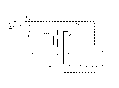
Figure 1 shows a schematic arrangement for hydrogenation according to present
process and
device. Input hydrocarbon stream feed and hydrogen, as well as recycle loops
are given with
wording and with reference numbers identifying the most relevant pieces of
equipment and two
essential lines.
DETAILED DESCRIPTION OF THE INVENTION
With reference to device, apparatus or unit, it is herein referred to the
process equipment that
is arranged to provide the entity, wherein hydrogenation processes and the
campaign change
process according to the present invention can be run. The unit or device
comprises reactors,
heat exchangers, separators, compressors, pumps, valves, controls and
necessary piping to
set up the system. Typically, a unit has an inlet providing the feed, the main
stream, recycle
loops, and outlet leading to further unit(s) and providing products.
As used herein, dearomatisation of hydrocarbon streams or distillates denotes
saturation
reactions reducing double bonds of aromatic compounds to cycloparaffins. In
dearomatisation,
hydrogen gas is typically provided in excess in the presence of a catalyst.
The typical aromatic
compounds to be saturated comprise benzene, toluene, tetramethylbenzene,
diethyl
methylbenzene, pentylbenzene, and indene. Possible polyaromatic hydrocarbons
comprise
CA 3037408 2019-03-20
6
naphthalene and derivatives thereof, and anthracene and phenanthrene and
derivatives
thereof.
Many petroleum cuts or distillate fractions contain aromatic compounds which
are harmful for
the human health. Hence, dearomatisation is one of the most typical
hydrogenation reactions
needed in petrochemistry. In order to provide non- or low-aromatic hydrocarbon
products, a
number of dearomatisation processes have been developed. Principally, they are
based on
conversion of the aromatic compounds to the corresponding saturated
hydrocarbons by
reacting said aromatic compounds with hydrogen in the presence of a suitable
catalyst at
elevated pressure and temperature. After dearomatisation, the hydrogenated
products are
usually stabilized by removal of the light, volatile hydrocarbon components.
In typical applications, the definitions "non- or low-aromatic hydrocarbon
products" refer to
products wherein the aromatic content is 5 %-vol at maximum, in some
applications preferably
less than 0.5 %-vol.
Here, the term "olefin saturation" is used to refer to saturation reactions
reducing carbon-
carbon double bonds of olefinic compounds to produce paraffins. Olefins are
also known as
alkenes. By definition, they are compounds made up of hydrogen and carbon
which contain
one or more pairs of carbon atoms linked by a double bond. With hydrogenation,
said double
bonds (-C=C-) are saturated to single bonds (-C¨C-).
When saturated, cyclic olefins produce cycloparaffins. Saturation of acyclic
olefins provides n-
paraffins when the carbon chain is straight and i-paraffins, should the carbon
chain be
branched.
With hydrogenation is herein in general referred to a process comprising the
steps of feeding a
hydrocarbon stream into a hydrogenation unit, contacting said hydrocarbon
stream with
hydrogen in the presence of a catalyst in order to hydrogenate the aromatic
and/or olefinic
compounds contained therein to produce a saturated product, and recovering the
saturated
product from the high-pressure section of the hydrogenation process unit. In
general, the
theoretical aim is to saturate all double bonds present and hence complete
conversion.
However, a man skilled in the art is well aware that in practice, it is
sufficient that at least part of
the aromatic and olefinic compounds is hydrogenated, referring here to
conversion between 60
and 99.99 % of aromatic and/or olefinic compounds in the hydrocarbon stream.
It is also known
CA 3037408 2019-03-20
7
that the conversion is dependent on the process settings and conditions, and
hence,
hydrogenation as used herein refers to sufficient conversion.
Conversion aim is also dependent on the hydrogenation process choices. In the
present case,
when the process is conducted through both first and second zones, the
conversion within the
first zone may be from 60 to 99 %, whereby at least a part of the aromatic and
olefinic
compounds is hydrogenated. The remaining aromatic and/or olefinic compounds
are further
hydrogenated in the second hydrogenation zone leading to the desired overall
conversion,
such as from 90 to 99.99 %.
In the following description, the hydrogenation reactors involved are defined
as "the first
reaction zone" and "the second reaction zone". Basically, according to an
embodiment, the first
reaction zone consists of one reactor and the second reaction zone of one
reactor
correspondingly. However, either the first or the second reaction zone may
consist of two or
more reactors, referred to as front reactor and following reactor(s),
typically arranged in series,
wherein the order of reactors may be changed. Preferably the first reaction
zone comprises two
reactors. Alternatively, said reactors may be arranged parallel. With two or
more reactors within
first and/or second hydrogenation zone, substitutes may be provided. Hence one
reactor may
be in use while another within the same zone is offline during maintenance or
regeneration.
The hydrogenation reactions take place in fixed bed reactors filled with a
hydrogenation
catalyst. Temperature increase caused by the exothermic hydrogenation
reactions is controlled
by recycling part of the first reaction zone liquid effluent, here referred to
as "first intermediate
liquid stream", to the first reaction zone inlet. The recycle loop goes
through the first reaction
zone, in which the major part of the hydrogenation/saturation reactions takes
place. The
reactor(s) in the second reaction zone outside the cooling loop comprise a
hydrogenation
catalyst as well and contribute to ensuring the desired product
specifications.
The difference between said first and second reaction zones is that cooling
and liquid recycle
loop is arranged only for the first reaction zone. The main part of the
exothermic hydrogenation
reactions take place in the first reaction zone, and therefore dilution and
cooling provided by
the recycle loop are needed. The second reaction zone on the other hand,
contribute to driving
the hydrogenation conversion even further, with reactions producing less heat.
Hence, there
are no means for temperature control arranged within the second reaction zone.
CA 3037408 2019-03-20
8
The liquid recycle loop provides cooled first intermediate liquid stream from
the hot high-
pressure separator to the first reaction zone inlet to restrict the
temperature rise in the first
reaction zone to less than 60 C.
The temperature rise across the first hydrogenation reaction zone is
controlled by liquid recycle
loop in which cooled first intermediate liquid stream is recycled from the hot
high-pressure
separator to the first reaction zone inlet. Liquid recycle rate is typically
from 0.5 to 15 times the
fresh feed rate. Said recycle provides control both by providing cooled liquid
and by diluting the
feed, thereby restricting the reaction rate and temperature increase at the
hydrogenation.
By arranging the cooling with recycling a part of the first intermediate
liquid stream, separated
from the outlet of the first reaction zone as a liquid recycle stream back to
the inlet of said first
reaction zone, the process can be kept effective and the scale optimized.
The reactors referred to herein can be defined as hydrogenation reactors. A
man skilled in the
art knows different reactor designs and applicability to different reactions.
In case there are
more than one reactor in the first reaction zone or second reaction zone,
having reactors
essentially similar to one another within one zone provides benefits through
process controls.
The hydrogenation reaction applied herein is catalytic hydrogenation. Hence,
the first and
second reaction zones comprise one or more catalytic beds. Preferably the
reactors in the first
and second reaction zones are trickle bed reactors. These have shown to be
especially
advantageous under present conditions, where pressure is kept constant. They
also contribute
to the objects of overall energy efficiency.
A number of hydrogenation catalysts is known in the art. Said catalysts may be
provided on a
support, typical supports comprise high melting oxides. Known hydrogenation
catalysts for
petrochemistry typically comprise a metal selected from platinum, iron or
nickel. Of these,
nickel has been shown to provide the desired performance and has been used in
the present
experiments.
For hydrogenation reactions in both first and second hydrogenation zone,
hydrogen is provided
in excess, typically from two-fold to ten-fold excess. Hydrogen feed may
comprise make-up
hydrogen and recycle hydrogen. Make-up hydrogen, which can also be referred to
as fresh
hydrogen, is supplied from a dedicated hydrogen generation unit. Recycle
hydrogen is
obtained from cold high-pressure separator after the second reaction zone.
CA 3037408 2019-03-20
9
Hydrogenation process
Different feedstocks are hydrogenated in the same hydrogenation unit. Hence,
herein is
provided a process for hydrogenation of a hydrocarbon stream comprising
olefinic compounds,
aromatic compounds or a combination thereof, which process comprises the steps
of:
i) feeding the hydrocarbon stream and hydrogen into a first reaction zone of a
hydrogenation
process unit,
ii) hydrogenating in the first reaction zone in the presence of a catalyst at
least part of said
aromatic compounds, olefinic compounds or both compounds to produce a first
intermediate,
iii) cooling and separating said first intermediate into liquid stream and gas
stream,
iv) conducting the first intermediate gas stream to a second reaction zone of
the hydrogenation
process unit
v) conducting said first intermediate liquid stream to
a) the inlet of the first reaction zone as a liquid recycle stream in order to
restrict
the temperature rise in the first reaction zone to less than 60 C, and to
b) a second reaction zone, wherein the remaining aromatic compounds, olefinic
compounds or combination thereof contained in said first intermediate liquid
stream are hydrogenated with the first intermediate gas stream in the presence
of
a catalyst to produce a saturated product, or
c) a liquid bypass line, which bypasses the second reaction zone, wherein said
first intermediate liquid stream comprises a saturated product,
vi) separating said saturated product into liquid product stream and a gas
recycle stream,
vii) recovering the liquid product stream from the hydrogenation process unit;
wherein said steps from i) to vii) are conducted at a constant pressure
selected from 2 - 8 MPa.
The pressure within steps from i) to vii), i.e. within the high-pressure
section of the
hydrogenation process, is maintained essentially constant at a pressure
selected from
2 - 8 MPa. Hence, once the pressure is set in the cold high-pressure
separator, the same
CA 3037408 2019-03-20
10
pressure is set for the reactors, heat exchangers, separators, recycles and a
bypass. Only after
the liquid product is recovered from the separator, is the pressure dropped at
the stabilisation.
The set pressure is a constant pressure selected between 2 and 8 MPa,
preferably between
3 - 6 MPa. Said constant pressure is maintained even through the campaign
changes.
According to preferred process conditions, the hydrocarbon stream is contacted
with hydrogen
at an amount of 25 to 500 Nm3 hydrogen/m3 hydrocarbons of the feedstock, at a
temperature
from 50 to 270 C, and at a LHSV from 0.2 to 10 1/h. Among these standard
process controls
LHSV refers to volumetric liquid hourly space velocity indicating the reactant
liquid flow
rate/reactor volume.
The hydrogenated stream from the outlet of said first reaction zone is herein
referred to as the
first intermediate. Said first intermediate is separated into a first
intermediate gas stream and a
first intermediate liquid stream. Said separation of first intermediate is
conducted by means of a
hot high-pressure separator.
In cases where the conversion after the first reaction zone is satisfactory,
said first intermediate
liquid stream is divided between liquid recycle loop and liquid bypass line.
Because there is no
need for further hydrogenation, the conduct through said liquid bypass line
transfers said first
intermediate liquid stream into saturated product in terms of the present
description. Hence, in
the liquid bypass line, the first intermediate liquid stream comprises a
saturated product. Due to
the process design, the gas stream from the outlet of the second reaction zone
is combined
with said saturated product and led to cold high-pressure separator.
In case the option of reacting said first intermediate liquid stream in the
second reaction zone is
applied, the unsaturated hydrocarbons remaining after the first reaction zone
are then reacted
with hydrogen-rich first intermediate gas stream and thereby saturated product
obtained. Said
saturated product together with gases are led from the outlet of the second
reaction zone to the
cold high-pressure separator.
Separation to liquid and gas or vapor stream in step vi) yields the saturated
product as liquid
and separated gas stream. According to a preferred embodiment, the separated
gas stream
from step vi) is conducted as hydrogen recycle stream to the inlet of the
first reaction zone.
This allows the use of excess hydrogen and effective use thereof. Said
separated gas stream
CA 3037408 2019-03-20
11
may in other embodiments be lead to other processes consuming hydrogen outside
the
hydrogenation unit.
The present inventors have found advantages of the present process being
related to the
constant pressure maintained through the hydrogenation processes within the
high-pressure
section of the hydrogenation unit. As used herein, the high-pressure section
includes reactors,
separators and recycle gas compressors. In practice, in process design a
pressure between
2 and 8 MPa is selected and set, and thereafter the process is conducted at
this set pressure
regardless the hydrocarbon stream as feedstock and product of choice.
Therefore, it is
beneficial to use equipment contributing to constant pressure and avoiding
pressure losses. It
was a surprising finding that different feedstocks may be hydrogenated to
fulfil different quality
demands applying one process and within one device at one selected pressure.
Accordingly, the process comprises at least one high-pressure separator.
Preferably one hot
high-pressure separator is situated downstream from the first hydrogenation
reaction zone and
separates the cooled intermediate into gas stream to be led to the second
reaction zone and
liquid stream. The hot high-pressure separators and cold high-pressure
separators are
commercially available and often referred to as HHPS and CHPS respectively.
When used as feeds for the present process, hydrocarbon streams comprise
olefinic
compounds less than 70 wt-%, preferably less than 50 wt-%, more preferably
less than
30 wt-% of the total feed mass. Such feeds have been considered too light to
be fed to a
process capable of heavier hydrocarbon stream hydrogenation.
According to an embodiment, the feed comprises aromatic compounds less than 70
wt-%,
preferably less than 50 wt-% and most preferably less than 30 wt-% of the
total feed mass.
Furthermore, very different feeds have been found being hydrogenated with the
present
method. Contrarily to expectations, possible feedstocks and processes for the
present
hydrogenation process and device are light naphtha, full range naphtha and
middle distillates
comprising aromatics, olefins or both.
When used as a feed hydrocarbon stream in the present hydrogenation unit,
light naphtha
(feed A) through hydrogenation or saturation of olefins produces highly
saturated 04, C5, C6
hydrocarbons with low olefins content. In the same unit, full range naphtha
(feed B) may be
used as the feed. In case of full range naphtha as a feed hydrocarbon stream,
the present
CA 3037408 2019-03-20
12
hydrogenation provides through dearomatisation of benzene and other aromatics,
benzene-
free C5, C6, 07 hydrocarbons. In case of middle distillates, gasoil or light
gasoil as the feed
(feed C) the hydrogenation is again dearomatisation of benzene, other
aromatics and heavier
polyaromatics, from which low aromatic solvents are produced.
The present inventors have now shown that feeds generally considered too
different to be
processable in the same hydrogenation unit can be run in subsequent campaigns.
Without
being bound to order of said feeds, at least two feedstocks can be fed
sequentially to the
present hydrogenation process.
Said feedstocks may differ from one another as to distillation range,
hydrocarbon chain length
given as carbon number range, and aromatic and olefinic compound content.
Hence, the
hydrocarbon stream comprising olefinic compounds, aromatic compounds or a
combination
thereof fed to the process can be defined as a hydrocarbon fraction wherein 90
%-wt of the
hydrocarbons:
a. have a distillation range defined by an initial boiling point from -10
to 230 C, and
a final boiling point up to 330 C according to standard ASTM D-86, and
b. have a carbon number range wherein the difference between the lower
carbon
number limit and higher carbon number limit is from 0 to 5, preferably from 0
to 3 and said
carbon number range is a subrange of carbon numbers from 04 to 017.
The hydrocarbon stream used as feed to hydrogenation is typically a
hydrocarbon cut obtained
from fractionation of fossil or renewable feedstock. Fractionation yields
cuts, wherein 90 %-wt
of the hydrocarbons have such carbon numbers that the difference between the
lowest carbon
number and the highest carbon number is 5 or less, thus their carbon chain
lengths are close
to one another. Hence, if the lowest carbon number of said subrange was 06,
the range
following this definition could be C6 ¨ C11, 06 ¨ 010, 06 ¨ 09, 06 ¨ 08, 06 ¨
07 or 06. If the
difference was limited to from 0 to 3, the subranges with the same lower
carbon number limit
could be hydrocarbons having carbon numbers 06 ¨ 09, C6 ¨ 08, 06 ¨ 07 or 06.
Examples of said hydrocarbon stream as feedstock comprise:
CA 3037408 2019-03-20
13
A) a hydrocarbon stream wherein at least 90 % of the hydrocarbons are
04 - C6 hydrocarbons, and have a distillation range defined by an initial
boiling point
of -10 C, and final boiling point not exceeding 80 C according to standard
ASTM D-86,
B) a hydrocarbon stream wherein at least 90 % of the hydrocarbons are
05 - C8 hydrocarbons, and have a distillation range defined by an initial
boiling point of
57 C, and final boiling point not exceeding 140 C according to standard ASTM
0-86,
and
C) a hydrocarbon stream wherein at least 90 % of the hydrocarbons are
C11 - 016 hydrocarbons, and have a distillation range defined by an initial
boiling point of
230 C, and final boiling point not exceeding 330 C according to standard
ASTM 0-86.
To the present inventors, it was surprising to note that the present process
is operable and
provides desired results with feed A as defined above, which is relatively
light hydrocarbon
olefinic stream, with the same device and under same constant pressure as for
heavier
aromatic containing feeds, such as B or C.
According to an embodiment, the hydrocarbon streams as feeds are obtainable
from fossil
sources. Petroleum cuts, i.e. hydrocarbon streams originating from fossil
sources, typically
crude oil or shale oil, may comprise high proportions, even up to 90 wt-% of
the total weight of
aromatic compounds, which for most applications need to be removed or
converted into
paraffins. Cuts originating from fossil sources may contain olefins as well,
especially when
coming from petroleum cracking processes upstream, such as Fluid Catalytic
Cracking (FCC).
A range of hydrocarbon stream applicable as feeds originating from renewable
sources are
available. Abundant carbon sources, such as lignocellulosic biomass,
cellulose, hemicellulose,
starch, sugars, fats, oils provide renewable hydrocarbon streams through
different treatments
and refining. Hydrocarbon streams may also be produced by micro-organisms,
such as algae,
bacteria and fungi followed by appropriate refining. Depending on the source
and nature of the
hydrocarbon precursors, the hydrocarbon streams obtainable may comprise
olefinic or
aromatic compounds or combinations thereof.
An example feedstock for the renewable hydrocarbon stream may originate from
plant oils or
fats, or animal oils or fats, or fish oils or fats. Hydrocarbon streams may be
derived with known
technologies from: any kind of plant fats, plant oils, and plant waxes; any
kind of animal fats,
CA 3037408 2019-03-20
14
animal oils, animal waxes, animal-based fats, fish fats, fish oils, and fish
waxes; fatty acids or
free fatty acids obtained from plant fats, plant oils, plant waxes; animal
fats, animal oils, animal
waxes; fish fats, fish oils, fish waxes, and mixtures thereof by hydrolysis,
transesterification or
pyrolysis; fats contained in milk; metal salts of fatty acids obtained from
plant fats, plant oils,
plant waxes; animal fats, animal waxes; fish fats, fish oils, fish waxes, and
mixtures thereof by
saponification; anhydrides of fatty acids from plant fats, plant oils, plant
waxes; animal fats,
animal waxes; fish fats, fish oils, fish waxes, and mixtures thereof; esters
obtained by
esterification of free fatty acids of plant, animal and fish origin with
alcohols; fatty alcohols or
aldehydes obtained as reduction products of fatty acids from plant fats, plant
oils, plant waxes;
animal fats, animal waxes; fish fats, fish oils, fish waxes, and mixtures
thereof; recycled fats of
the food industry; fats contained in plants bred by means of gene manipulation
or genetic
engineering; dicarboxylic acids or polyols including diols, hydroxyketones,
hydroxyaldehydes,
hydroxycarboxylic acids, and corresponding di- or multifunctional sulphur
compounds,
corresponding di- or multifunctional nitrogen compounds, or compounds derived
from algae,
molds, yeasts, fungi and/or other microorganisms capable of producing
compounds mentioned
above or compounds similar to those.
When the hydrocarbon stream as feedstock for the present process is derived
from fatty-acid
rich renewable sources, the aromatic content is often intrinsically low. For
example, renewable
feed obtained from fatty acids or mono-, di- or triglycerides thereof by
hydrodeoxygenation and
optionally isomerisation, are substantially free from aromatics and easily go
below 1 wt-% due
to nature of the raw material. However, such feedstocks from renewable sources
often contain
olefinic unsaturated hydrocarbons.
The feed may also be a blend of hydrocarbon streams from fossil and renewable
sources or a
hydrocarbon stream obtained from processing such a blend. The feedstocks are
hence
obtainable from fossil sources, renewable sources or any combination thereof.
Different feeds require somewhat different temperatures in hydrogenation
processes. However,
the pressure may be kept substantially constant. Due to the high pressure
level maintained in
the system, there is no need for optimising the gas recycle.
According to an embodiment, the hydrogenated liquid product stream obtained
from the high-
pressure section of the hydrogenation unit is further fractionated into
products of defined boiling
ranges. The liquid product stream is stabilized in a stabilizer column,
optionally distilled to be
CA 3037408 2019-03-20
15
divided into fractions, and sent to the storage. The fractionation step is
carried out outside the
high-pressure section and at a pressure from 1 kPa to 1 MPa absolute.
Items which are left for the man skilled in the art to optimise are catalyst
volume, reaction
temperatures and recycle gas rate, hydrogen/feed ratio etc.
An embodiment for campaign change
When the present hydrogenation device is used for hydrogenation of a feed, it
has been found
that feeds typically requiring very different hydrogenation conditions and
process equipment
may be processed with the same unit. It is especially interesting, that
dearomatisation and
saturation of olefins, can successfully be conducted in the same hydrogenation
device.
However, a specific advantage obtainable through the present process and
device is a novel
process for campaign change. Compared to processes known from the prior art,
the present
hydrogenation device provides means for running very different feeds for
remarkably different
hydrogenation reactions, wherein the change from one feed to another provides
improvements
as to downtime and product and reactant losses during campaign change are
concerned.
Smooth change from one feed to another is essential to minimize down-time and
product
mixing.
Traditionally, process chemistry uses terms batch process and continuous
process. Continuous
processes are typically run as long a period as possible, only stopped for
maintenance and
started again with the same feed, conditions and products. With the term
"campaign" is here
referred to a continuous process, which is run for a period of time. The
present process can be
set up and run using one feed for a period, and then, through the method for
campaign change,
run using another feed for another period. In this context, the campaign
length may vary
between 1 and 30 weeks, typically between 2 and 20 weeks. The benefits of the
present
method for campaign change are best noticed when the campaigns are relatively
short (for
example from 2 to 6 weeks), and changes consequently frequent. However, for
overall
productivity a balance between campaign changes and lengths is dependent on
several
factors. Anyway, the present method for campaign change provides benefits over
traditional
changes involving a complete shut-down of the unit.
CA 3037408 2019-03-20
16
According to an embodiment, the present hydrogenation process further
comprises steps for a
change from one campaign with a hydrocarbon stream as a feed to a next
campaign with
another hydrocarbon stream as a feed:
= keeping the pressure essentially constant within the high-pressure
section;
= flushing the catalysts in first and second hydrogenation zones with
hydrogen;
and
= draining liquids from the unit.
More specifically, a detailed example of the process for campaign change
comprises the
following steps in the order herein given, which however may be partly
overlapping. Hence,
within a hydrogenation unit comprising first and second hydrogenation zones,
heat exchangers,
high-pressure separators, a stabilizer, liquid recycle and hydrogen recycle, a
method for a
change from one campaign to a next campaign comprises the steps of:
a. draining liquids from the hydrogenation zones;
b. keeping the pressure essentially constant and monitoring the temperatures
in
the reactors;
c. starting a liquid recycle from the stabilizer bottom to the inlet of the
first reaction
zone;
d. cutting off the feed to the first reaction zone;
e. stopping the liquid recycle at a time point where the reactor temperature
measurements show essentially constant temperatures;
f. flushing the catalysts with hydrogen;
g. draining liquids from the unit;
h. setting temperatures to the values required for the next campaign;
i. filling the stabilizer column and the feed drum with next feed;
CA 3037408 2019-03-20
17
j. pumping preheated next feed to the first reaction zone to start the next
campaign.
Recycle is established from the product cooler to the feed drum and the fresh
feed to the unit
can be stopped.
Liquid recycle shall be continued at normal operating pressure and the
operating temperature
prevailing just before starting the recycle as long as any temperature profile
is observed in the
reactors. Temperature in the hot high-pressure separator shall however be
reduced.
The hydrogen flushing shall be done with once through hydrogen. Alternatively
recycle gas
compressor can be used. Anyway, hydrogen flowrate should be maximized. Gas
purge shall be
sent through control(s) and separator(s) to a flare.
Hydrocarbons flushed from the reactors are collected in the hot high-pressure
separator and
cold high-pressure separator. So, it is important to minimize levels in the
high-pressure
separators before starting the hydrogen flushing. It is also important that
the air coolers are in
operation with adequate duty (louvers open) to cool the inlet stream to the
high-pressure
separators to 40 C or below to condense hydrocarbons as well as possible.
During hydrogen flushing, operating pressure in the cold high-pressure
separator can be
reduced. In general, flushing temperature should be same as the operating
temperature for the
earlier feed.
Through this process, advantages can be achieved. Firstly, through careful
draining of the
liquid from the system, mixing of different campaigns can be successfully
avoided. The
hydrogen flushing effectively removes hydrocarbons from the system. However,
conversely to
prior understanding, it also provides advantages to catalysts through flushing
off remains of the
campaign feed, intermediates and products, which purifies the catalysts for
the next campaign.
This is especially beneficial considering the heaviest aromatic compounds,
which otherwise
could accumulate to the recycle or contaminate the catalyst. An important
feature of the
process for campaign changes is the arrangement with which the liquid
hydrocarbons are
drained from the unit while hydrogen recycle is maintained in operation.
Further, since the
hydrogen pressure is maintained, the hydrogenation device is kept running and
the start of the
next campaign is quicker once feed is introduced to the feed drum. Thereby,
pressure losses
are decreased contributing to the overall economics of campaign changes.
CA 3037408 2019-03-20
18
The present hydrogenation unit comprises a hydrogenation device. A man skilled
in the art
understands that the hydrogenation unit is connected to other unit processes
upstream and
downstream. Roughly, the device comprises feed tanks, hydrogenation reactors,
separators,
recycle lines, heat exchangers, and is connected to product stabilisation
through distillation.
A device for implementing the present process comprises a first hydrogenation
reaction zone
with at least one hydrogenation reactor, a second hydrogenation reaction zone
with at least
one hydrogenation reactor, a liquid recycle loop from a hot high-pressure
separator to the inlet
of the first reaction zone, means for conducting the first intermediate gas
stream from said hot
high-pressure separator to the second reaction zone, means for conducting at
least part of the
first intermediate liquid stream to the second reaction zone, a line for
liquid bypassing the
second reaction zone, a cold high-pressure separator and a gas recycle loop
from the cold
high-pressure separator to the inlet of the first reaction zone.
With reference to figure 1, the present process and device for hydrogenation
may be described
comprising at least one reactor within the first hydrogenation reaction zone
1. The hydrocarbon
stream as feed is conducted to the first hydrogenation reaction zone 1 through
the feed drum 9.
A hot high-pressure separator 3 separates the cooled first intermediate from
the said first
hydrogenation reaction zone to provide a first intermediate liquid stream and
a first
intermediate gas stream 5. A part of the first intermediate liquid stream is
directed as liquid
recycle back to the first hydrogenation reaction zone reactor(s). The rest of
the first
intermediate liquid stream is conducted either to the second hydrogenation
zone 2 downstream
from said separator 3 for further hydrogenation or to a liquid stream bypass
line 4 arranged to
bypass the second hydrogenation zone 2. Optionally both can be applied. From
the hot high-
pressure separator 3, the gas stream is arranged to be directed to the second
hydrogenation
zone 2. From the outlet of the second hydrogenation zone, a saturated product
and gas are
cooled and directed to cold high-pressure separator 6 from which the liquid
product stream is
led to product stabilisation section 7 and fractionation 8. The gas stream
from said cold high-
pressure separator 6 is conducted as hydrogen recycle back to the first
hydrogenation reaction
zone and combined with make-up hydrogen to be fed back to the process.
Alternatively, the
gas stream from said cold high-pressure separator 6 is conducted out of the
high-pressure
section (dashed line upwards from 6) of the hydrogenation unit.
CA 3037408 2019-03-20
19
The hydrogenation process and device further comprise heat exchangers,
compressors, and
further standard process equipment not specifically described in the figure.
The hydrocarbon stream as feedstock is conducted to the first hydrogenation
reaction zone 1
through the feed drum 9, after which the feed is pressurized to the set
reaction pressure. The
hydrocarbon stream is preheated (not shown) utilising the heat formed in
exothermic reactions
and collected from cooling down of the outlet stream of the first
hydrogenation reaction zone.
The hydrocarbon stream feed is combined with recycle hydrogen and make-up
hydrogen and
further heated up (not shown) to the desired feed temperature.
Still in reference to figure 1, according to an embodiment the process
configuration used for
hydrogenation of the hydrocarbon stream comprises at least one hydrogenation
reactor in the
first reaction zone 1 and at least one hydrogenation reactor in the second
reaction zone 2 for
optionally completing the conversion.
Since the process and device are especially suitable for flexible
hydrogenation of different
feedstocks, several options for running the process are available. In cases
where the
requirements for conversion are high, the first intermediate liquid stream
obtained from the hot
high-pressure separator is fed to the second hydrogenation zone 2. Even though
the need for
saturation is relatively small due to the majority of hydrogenation taking
place in the first
reaction zone, the unsaturated olefins, aromatic compounds or a combination
thereof
remaining in said first intermediate liquid stream are hydrogenated in the
second hydrogenation
zone with high conversion.
In cases where the conversion obtained in the first reaction zone is
sufficient, there is no need
to lead the first intermediate liquid stream to the second reaction zone. In
this case, only the
gas stream passes through the second reaction zone. The present inventors have
found this
being advantageous both by allowing maintenance of the constant pressure on
the high-
pressure section with different feeds and product requirements, and by
flushing the catalyst in
the second reaction zone and thereby purifying the catalyst. Whether to
conduct the first
intermediate liquid stream to the second reaction zone is controlled by use of
bypass line 4.
The second reaction zone 2 is operated when required for desired product
specifications. Such
cases may apply to feedstocks containing olefinic or aromatic compounds or
combinations
thereof, which are not hydrogenated to the required level in the first
reaction zone. Other cases
CA 3037408 2019-03-20
20
may be related to need to comply with such product specifications which are
not met with
hydrogenation in the first reaction zone only. Hydrogen-rich gas is separated
from the liquid
effluent in a cold high-pressure separator 6 and recycled to the first
reaction zone 1 inlet or
conducted out of the high-pressure section (dashed line upwards from 6) of the
hydrogenation
unit.
It is essential that, the first intermediate gas stream 5 from the separator 3
is always guided
through second hydrogenation zone. From the second reaction zone 2, the outlet
stream is fed
to the cold high-pressure separator 6 wherefrom the saturated product to the
stabilisation
section 7. There is no recycle of the liquid stream from cold high-pressure
separator 6 to any
reactor. Said stabilisation section 7 (details not shown) is maintained under
process conditions
sufficient to produce products substantially free of hydrogen and light
hydrocarbons. The
stabilized product may be fractionated in distillation column 8 into fluids of
defined boiling
ranges.
In figure 1, a dashed line square denotes the high-pressure section of the
present process and
device within the hydrogenation unit. The equipment within said dashed square
are set to a
constant pressure selected between 2 and 8 MPa. It is clear to a man skilled
in the art that, a
set constant pressure in practice shows an insignificant pressure profile,
typically around a
couple of bars showing slightly higher pressure at the inlet for the first
reaction zone, and
decreasing towards the cold high-pressure separator. However, the present
inventors have
found the substantially constant pressure within the high-pressure section of
the present
process and device providing advantages through energy efficiency, low
hydrogen
consumption and decreased process down-time.
According to a preferred embodiment a device and process for hydrogenation
comprises two
reactors in the first reaction zone, herein referred to as front reactor and
following reactor. This
embodiment is studied in detail in the examples 1 and 2 of this disclosure. In
the examples, the
process configuration used for hydrogenation of the feed comprises two trickle-
bed
hydrogenation reactors in series in the first reaction zone and one reactor in
the second
reaction zone 2 for completing the conversion. Preferably most of the
exothermic reactions
take place in the front reactor, which consequently has higher temperature
increase. When the
catalyst deactivates, reaction moves gradually to the following reactor in the
first hydrogenation
CA 3037408 2019-03-20
21
reaction zone. This development is further illustrated in the examples through
analyses relating
to start of the run and end of the run conditions.
According to one embodiment of a device and process for hydrogenation
comprising two
reactors in the first reaction zone, it is feasible to load fresh catalyst in
the front reactor after
which the order of reactors within said first reaction zone can be changed.
The temperature rise in the first hydrogenation reaction zone is controlled by
liquid recycle in
which cooled first intermediate liquid stream is recycled from the hot high-
pressure separator 3
to the first hydrogenation reaction zone inlet.
EXAMPLES
The following examples are provided to better illustrate the claimed invention
and are not to be
interpreted as limiting the scope of the invention. To the extent that
specific materials are
mentioned, it is merely for purposes of illustration and is not intended to
limit the invention. Two
very different hydrocarbon streams were used as feeds (referred to as feed A
and feed C or
feeds). One skilled in the art may develop equivalent means or reactants
without the exercise
of inventive capacity and without departing from the scope of the invention.
It will be
understood that many variations can be made in the procedures described herein
while still
remaining within the bounds of the present invention.
Example 1, LIGHT OLEFINIC NAPHTHA AND MIDDLE DISTILLATE FEED CONTAINING
AROMATICS AS FEEDS
The hydrogenation device corresponded to the embodiment described in Figure 1.
The first
reaction zone comprised two hydrogenation reactors, which were operated in
series. The front
reactor had higher temperature increase due the exothermic reactions taking
place
predominantly therein. Temperature increase in the front reactor was
controlled by diluting
reactor feed with liquid recycled from the reactor outlet to inlet. The second
reaction zone inlet
temperature was not controlled but determined by the front reactor outlet
temperature.
The reactor section feed consisted of fresh feed, liquid recycle, make-up
hydrogen and recycle
gas. Liquid recycle diluted contents of the reactive components and thus
controlled
temperature increase. Make-up hydrogen was added to cover hydrogen consumption
in the
CA 3037408 2019-03-20
22
reactions. Recycle gas was adjusted to maintain adequate hydrogen to reactive
ratio in the
reactor inlets.
The device was operated with two different feeds. Feed A was a light mainly 05-
hydrocarbon
containing olefinic naphtha and feed C a middle distillate hydrocarbon stream
containing
aromatics. Operation with different feeds was done in relatively short
campaigns of two or three
weeks. Olefin content of feed A was 30 wt-% and aromatic content of feed C was
20 wt-%.
Required reactor inlet temperature depends on the feed type and catalyst
deactivation. For
Feed A, the first reactor inlet temperature was 70 C with a fresh catalyst
for start of run
conditions (SOR) and 150 C with a deactivated catalyst for end of run
conditions (EOR). The
corresponding temperatures for Feed C were 120 C (SOR) and 220 C (EOR).
Separation of the recycle gas from the liquid comprising the saturated product
and recycling of
it with the recycle gas compressor requires low temperature in the high-
pressure separator.
This results in additional energy consumption, when recycle gas stream is
reheated to the
optimal reactor operating temperature. The heat formation of the exothermic
reaction can be
utilized for reactor feed heating by installing a hot high-pressure separator,
from which liquid
can be recycled at high temperature, whilst the cold high-pressure separator
temperature is set
by gas recycle requirements.
The additional improvement in this invention is that energy consumption is
optimized for all
design feed cases comprising both design feeds in SOR and EOR conditions. As
the invention
covers a wide range of feeds, with varying properties, the design feed
compositions can be
considered as examples illustrating different distillation ranges and reactive
olefin or aromatics
contents. Based on the teaching of the present invention, the energy
consumption can be
easily reoptimized for the feeds with properties differing from the example
feeds.
To demonstrate the energy effectiveness obtained with the present invention,
reactor section
energy consumption was calculated with regard to reactor feed heater and at
air cooling.
These are given in table 1 for feeds A and C.
CA 3037408 2019-03-20
23
Table 1. Reactor section energy consumption according to the present
invention.
Reactor feed heater (kW) Air cooling (kW)
Feed A start of run 140 1729
Feed A end of run 200 1790
Feed C start of run 97 895
Feed C end of run 1083 1875
Feed was pumped to the first reaction zone through reactor feed/effluent
exchanger and
reactor feed heater to the front hydrogenation reactor inlet. The reactor
liquid recycle and
hydrogen feed consisting of make-up hydrogen and recycle gas was mixed with
the fresh feed
upstream of the reactor feed heater, by which the reactor feed stream was
adjusted to the
desired inlet temperature.
The effluent from the first reaction zone, i.e. the first intermediate was
cooled first in the reactor
feed/effluent exchanger and then in air cooler and collected in the hot high-
pressure separator.
The hot high-pressure separator temperature was set to optimize total energy
consumption.
The first intermediate from hot high-pressure separator as liquid was divided
into two streams:
the liquid recycle to reactor feed heater, and the second reaction zone feed.
Vapor (the first
intermediate gas stream) from the hot high-pressure separator was combined
with the second
reaction zone liquid feed. The second reaction zone converted the last traces
of reactive
components left in the effluent from the reactors of the first reaction zone.
If the reactors in the
first reaction zone function properly, the reactor in the second reaction zone
should not show
any temperature profile.
Effluent comprising the saturated product from the second reaction zone was
further cooled to
40 C in the air cooler and collected in the cold high-pressure separator.
Pressure of the liquid
from the cold high-pressure separator was reduced and sent to low pressure
section for
distillation.
The separated gas stream from the cold high-pressure separator was sent to the
hydrogen
recycle compressor suction through a knock-out drum. Recycle gas from the
compressor outlet
was mixed with the make-up hydrogen and sent to the reactor feed heater.
CA 3037408 2019-03-20
24
The energy economy and savings obtained by the present invention are best
illustrated in
table 3, where the differences in energy consumption with and without the hot
high-pressure
separator are listed.
Comparative example 1, LIGHT OLEFINIC NAPHTHA AND MIDDLE DISTILLATE FEED
CONTAINING AROMATICS AS FEEDS
A hydrogenation of the same feeds as in example 1 was simulated. The
hydrogenation device
was otherwise exactly the same as in example 1, but without the hot high-
pressure separator.
Results calculated as energy consumption are given in table 2, where the terms
are the same
as in table 1.
Table 2. Reactor section energy consumption without hot high-pressure
separator.
Reactor feed heater (kW) Air cooling (kW)
Feed A start of run 525 2114
Feed A end of run 3314 4904
Feed C start of run 1805 2603
Feed C end of run 4681 5474
Table 2 shows that without the hot high-pressure separator the energy
consumption is very
different depending on the feed or catalyst activity. As can be seen, EOR
conditions give more
potential for energy savings that SOR conditions, and heavy feed more than
light feed.
Comparison between tables 1 and 2 shows that energy consumption can be reduced
with hot
high-pressure separator. It also shows how the device utilising features of
the invention is able
to maximize utilisation of the energy saving potential with different feeds
and catalyst lifetime.
This is further clarified in table 3 showing how energy savings (calculated as
[energy
consumption according to the invention] ¨ [energy consumption of the
comparative example])
are achieved with hydrogenation process according to the present invention
during runs with
two different feeds.
CA 3037408 2019-03-20
25
Table 3. Difference between reactor section energy consumptions in example 1
and
comparative example 1 above.
Reactor feed heater (kW) Air cooling (kW)
Feed A start of run -385 -385
Feed A end of run -3114 -3114
Feed C start of run -1708 -1708
Feed C end of run -3598 -3599
The energy consumption results show some of the advantages obtainable with the
present
hydrogenation device and process for hydrogenation of two very different
feeds, namely light
olefinic naphtha (Feed A) and middle distillate feed (Feed C) containing
aromatics.
Example 2. OPERATION OF ALL CASES AT THE SAME PRESSURE AND CAMPAIGN
CHANGE WITHOUT DEPRESSURISATION
The hydrogenation device corresponded to the embodiment of example 1. The
device was
designed to operate with two different feeds. Feed A was a light mainly C5-
hydrocarbon
containing olefinic naphtha and feed C a middle distillate hydrocarbon stream
containing
aromatic compounds. Operation with different feeds was carried out in
relatively short
campaigns of two or three weeks. It was found that all feed cases comprising
light
C5 hydrocarbons as well as heavy gasoil cases can be operated at same pressure
ranging
from 2 to 6 MPa, when operating temperature and liquid recycle rate are
optimized. The
common operating pressure for all cases is advantageous in feed pump, recycle
gas
compressor and make up hydrogen compressor design.
Campaign change is started by reducing liquid levels in all vessels. Remaining
liquid is pushed
by hydrogen pressure from high-pressure reactor section to low pressure
distillation section
through special draining lines that have been located to avoid dead ends
collecting liquid.
Distillation is continued as long as possible so that on-spec product to
storage is maximized.
Catalyst in reactor is cleaned from hydrocarbons simultaneously by sweeping
with hydrogen
recycle.
By these measures, the earlier feed can be removed as well as possible so that
mixing of feeds
is minimized. Hydrogen pressure is maintained in the high-pressure section
until the new feed
is introduced. The stabilizer column is equipped with some start-up lines for
filling with new
CA 3037408 2019-03-20
26
feed beforehand to be able to heat the column so that it is ready to take the
new feed when it
arrives.
According to the present process and method, the campaign changes from one
hydrocarbon
stream as feedstock to another hydrocarbon stream as feedstock can be done
without
depressurisation of the high-pressure section, which results in savings in
hydrogen
consumption and time. As comparative examples, processes with pressure
variations were
simulated. Savings in the hydrogen consumption can be seen in the following
table 4, which
shows the amount of hydrogen needed for pressurisation of a high-pressure
section of the
hydrogenation unit designed for feed rate of 10-20 t/h when the original
pressure varies
between 0 and 3 MPa and the target pressure between 4 and 6 MPa.
Table 4. Effect of the variations in the pressure for the calculated hydrogen
consumption within
the high-pressure section.
Original Original Original Original
pressure 0 MPa pressure 1 MPa pressure 2 MPa pressure 3 MPa
Target pressure H2 290 kg H2 223 kg H2 149 H2 74 kg
4 MPa
Target pressure H2 365 kg H2 298 kg H2 223 H2 149 kg
5 MPa
Target pressure H2 439 kg H2 372 kg H2 298 H2 223 kg
6 MPa
The table illustrates how the pressure differences and depressurisation within
the high-
pressure section increases hydrogen consumption during campaign changes.
It will be apparent to a person skilled in the art that, as the technology
advances, the inventive
concept can be implemented in various ways. The subject matter in the above
described
embodiments may be combined in any permutations or manner. The same applies to
subject
matter of all dependent claims which may be used in any combination to
restrict the
CA 3037408 2019-03-20
27
independent claims. The invention and its embodiments are not limited to the
examples
described above but may vary within the scope of the claims.
CA 3037408 2019-03-20