Note: Descriptions are shown in the official language in which they were submitted.
CA 03037578 2019-03-20
WO 2018/053729
PCT/CN2016/099638
IMPROVED HEAT SINK AND HEAT DISSIPATION STRUCTURE
FIELD OF THE INVENTION
The present invention is related to heat sinks and heat dissipation
structures.
BACKGROUND
Excess heat is a problem in may items such as motors, batteries, electronics,
tools,
computers, chargers, etc. Many different designs and strategies exist to
actively and passively
dissipate unwanted heat. While some of these methods rely upon various heat
sinks, and even
heat sinks with air being blown directly thereupon by a fan, such a fan
requires additional energy
to operate and thus may cause other issues.
Certain passive heat dissipation structures are known and may use ambient air
to draw
away heat. However, such passive structures are less efficient than active
structures.
Accordingly, the inventors believe that a more effective strategy is needed to
improve
heat dissipation. Thus, there remains a need for improved heat sinks and heat
dissipation
structures.
SUMMARY OF THE INVENTION
An embodiment of the present invention relates to a printed circuit board
assembly
(PCBA) having a heat source, a heat sink, and an exit vent. The heat source
generates heat,
typically excessive heat and the heat sink conducts heat from the heat source
and heats up the
surrounding air to form heated air. The heated air then passes through the
exit vent which is
positioned adjacent to the heat sink.
Without intending to be limited by theory, it is believed that such a passive
venting
system is extremely efficient and permits the flow of the heated air itself to
create a low pressure
zone above the heat sink which then draws surrounding air to the heat sink.
This in turn further
cools the heat sink. Furthermore, such an embodiment may be virtually silent,
as no moving
1
CA 03037578 2019-03-20
WO 2018/053729 PCT/CN2016/099638
mechanical parts are needed.
An embodiment of the present invention also relates to a heat dissipation
structure
containing a fan to move air, a heat source distal from the fan, an exit vent
proximal to the fan,
and an airflow path running from the heat source to the fan to the exit vent.
The heat source
heats the air to form heated air. When the fan is activated, the fan draws air
through the airflow
path from the heat source and out of the exit vent.
Without intending to be limited by theory, it is believed that such a heat
dissipation
structure may be extremely efficient while also requiring little energy for
such a fan. Thus, it is
believed that the embodiment is actually more efficient than a fan which blows
air directly upon
a heat source, as it may draw comparatively more air past the heat source.
BRIEF DESCRIPTION OF THE DRAWINGS
Fig. 1 shows a cut-away side view of embodiment of the heat sink of the
present
invention;
Fig. 2 shows a partial, top perspective view of an embodiment of a PCBA of the
present
invention;
Fig. 3 shows a cut-away schematic view of an embodiment of the heat
dissipation
structure of the present invention; and
Fig. 4 shows a cut-away schematic view of an embodiment of the heat
dissipation
structure of the present invention.
The figures herein are for illustrative purposes only and are not necessarily
drawn to
scale.
DESCRIPTION OF THE PREFERRED EMBODIMENTS
Unless otherwise specifically provided, all tests herein are conducted at
standard
2
CA 03037578 2019-03-20
WO 2018/053729 PCT/CN2016/099638
conditions which include a room and testing temperature of 25 *C, and all
measurements are
made in metric units. Furthermore, all percentages, ratios, etc. herein are by
weight, unless
specifically indicated otherwise.
An embodiment of the present invention relates to a printed circuit board
assembly
(PCBA) having a heat source, a heat sink, and an exit vent. The heat source
generates heat,
typically excessive heat which could be detrimental to the long-term stability
of the PCBA, or
whatever the PCBA is installed within, and/or the excessive heat could cause
other problems.
The heat source is connected to the heat sink, and typically the heat source
is physically
connected to; or touching the heat sink. The heat sink conducts heat from the
heat source and
heats up the surrounding air to form heated air. The heated air then passes
through the exit vent
which is adjacent to, and typically directly above, the heat sink. Without
intending to be limited
by theory, it is believed that such a passive venting system is extremely
efficient and permits the
flow of the heated air itself to create a low pressure zone above the heat
sink which then draws
surrounding air to the heat sink. This in turn further cools the heat sink.
Furthermore, such an
embodiment may be virtually silent, as no moving mechanical parts are needed.
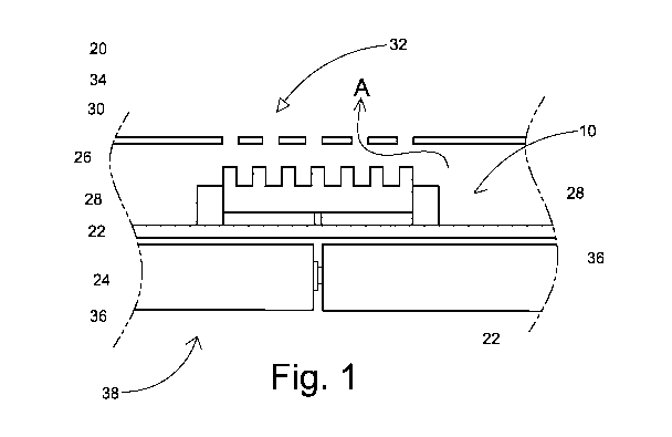
Turning to Fig. 1, which shows a cut-away side view of an embodiment of the
present
invention, we see a PCBA, 10, containing a heat source, 20, which generates
heat that needs to
be dissipated. In this embodiment the heat source, 20, is a set of field-
effect transistors (FETs),
22, typically from about 1 FET to about 32 FETs; or from about 2 FETs to about
16 FETs; or
from about 3 FETs to about 8 FETs; or about 4 FETs grouped together. Without
intending to be
limited by theory, it is believed that FETs, 22, grouped together can produce
an excessive
amount of heat which may need to be dissipated and/or removed. However, the
heat source need
not be a PET, but may be, for example, a battery, a battery case, a battery
pack, a motor, a
capacitor, an electrical circuit, etc. In an embodiment of the present
invention the heat source is
3
CA 03037578 2019-03-20
WO 2018/053729
PCT/CN2016/099638
selected from the group consisting of a battery, a motor, a transistor, a gear
box, and a
combination thereof; or a battery, a transistor and a combination thereof; or
a battery; or a
transistor.
The heat source, 20, in Fig. 1 is connected to a substrate, 24, which is the
mechanical
support for the PC BA. in an embodiment herein the substrate is formed from,
or contains, FR-4
(a.k.a. "FR4"), a glass-reinforced laminate sheet formed from a woven
fiberglass cloth and an
epoxy resin. Such a substrate is standard and well-known in the electronics
and PBCA art for
holding electronic components and for.
In Fig. 1, the heat source, 20, directly contacts the heat sink, 26, which in
turn conducts
heat away from the heat source, 20. The heat sink is typically of a shape
which intends tin
increase the surface area thereof, so as to better dissipate the heat to the
surrounding air.
Accordingly, the heat sink may have a set of furrows and a set of raised
ridges so as to increase
the surface area over, for example, a plain rectangular block. Designs to
increase the surface
area of the heat sink are known to those in the relevant art, and any such
design may be useful in
the present invention.
In the embodiment of Fig. 1, the heat sink, 26, is affixed to the substrate,
24, and is held
in place by the heat sink holder, 28. In this embodiment, the heat sink
holder, 28, is affixed to
the heat source, 20. In an embodiment herein, the heat sink holder is affixed
to the substrate. In
an embodiment herein, the heat sink holder is affixed to the heat source; or
the heat sink holder is
permanently affixed to the heat source; or the heat sink is removably-affixed
to the heat source.
In an embodiment herein, the heat sink holder is physically connected to the
heat source.
The heat sink may be formed of any suitable thermally-conductive material,
such as a
metal, a plastic, and a combination thereof; or a metal. In addition, the
material for the heat sink
should also be relatively sturdy and preferably cheap. The metal may be, for
example, copper,
4
CA 03037578 2019-03-20
WO 2018/053729 PCT/CN2016/099638
iron, aluminium, tin, brass, and a combination thereof; or copper aluminium,
brass and a
combination thereof; or copper.
The heat sink holder is typically formed of a material which is less thermally-
conductive
than the heat sink, is relatively resistant to heat (i.e., will not melt or
burn at the relevant
temperatures), is easy to form into the desired shape and is relatively cheap
to produce.
Accordingly, in an embodiment herein, the heat sink holder is formed of a
plastic; or a high-
impact plastic; or a thermally-resistant plastic.
Fig. 1 also shows a housing, 30, distal from the heat source, 20. The housing,
30, may be,
for example, a battery housing, a generator housing, a power tool housing, a
battery pack housing,
a charging station housing, etc. as desired. The housing, 30, contains an exit
vent, 32, formed
from a plurality of parallel slits, 34, in the housing, 30. In an embodiment
herein, the parallel
slits form a pattern, such as a grid pattern, a diagonal pattern, etc.
In Fig. 1, this housing, 30, also aligns the substrate, 24, opposite to the
exit vent, 32, with
the heat source, 20, the heat sink, 26, and the heat sink holder, 28,
therebetween. In order to
maximize dissipation of the excessive heat and heated air into the ambient air
outside of the
housing, 30, the exit vent, 32, is adjacent to; or directly above, the heat
sink, 26, although other
positions adjacent to the heat sink, 26, are also within the scope of the
present invention.
The heat sink, 26, conducts heat away from the heat source, 20, and heats up
the air
surrounding the heat sink to form heated air. The heated air then rises and
flows out of the exit
vent, 32. Without intending to be limited by theory, it is believed that this
rising heated air
creates a low pressure zone above the heat sink, 26, which then draws
additional air past the heat
sink, 26, and out of the vent, 32, as shown by arrow A. Such a design
therefore increases the
efficiency and cooling of the heat sink by drawing not only air directly
touching the heat sink but
additional air via the Bernoulli principle.
CA 03037578 2019-03-20
WO 2018/053729
PCT/CN2016/099638
In Fig. 1, it can be seen that the PCBA, 10, is connected to a series of
batteries, 36, which
are part of a battery pack, 38. The FETs, 22, may generate excessive heat
during, for example,
the charging and/or discharge of the battery pack.
In Fig. 2 shows a partial, top perspective view of an embodiment of a PCBA,
10, of the
present invention, which is part of a battery pack, 38. The FET, 22, and the
heat sink holder, 28,
are affixed to the substrate, 24. The heat sink holder, 28, is affixed to the
heat sink, 26, and
prevents it from breaking contact with the heat source, 20.
Another embodiment of the present invention relates to a heat dissipation
structure
having a fan, a heat source distal to the fan, an exit vent proximal to the
fan, and an airflow path.
The airflow path runs from the heat source to the fan to the exit vent. The
heat source heats the
air to form heated air. When the fan is activated, the fan draws air through
the airflow path from
the heat source and out of the exit vent.
Fig. 3, shows a cut-away schematic view of an embodiment of the heat
dissipation
structure, 40, of the present invention. A power tool, 42, has a housing, 30,
which contains a
battery pack, 38, which contains internal batteries, 36 that form the heat
source, 20. In an
embodiment herein, the heat dissipation structure herein contains the PCBA
described herein.
The power tool useful herein may be any battery-operated tool such as, but not
limited to
a drill, a vacuum, a blower, a lawn mower, a hedge trimmer, a saw, a hammer-
drill, an edge
trimmer, a line trimmer, a sander, a nail gun, a staple gun, a router, an
etcher, and a combination
thereof; or a drill, a sander, a vacuum, a blower, a lawn mower, an edge
trimmer, a line trimmer,
and a combination thereof.
The housing, 30, contains an exit vent, 32; or a plurality of exit vents,
formed by slits, 34,
in the housing. The housing, 30, also contains one or more entrance vents, 44,
that is also
formed by slits, 34, in the housing. The housing is for a power tool and is
well-known in the art.
6
CA 03037578 2019-03-20
WO 2018/053729 PCT/CN2016/099638
Such a housing is typically formed of a plastic, a resin, rubber, and a
combination thereof. The
entrance vent, 44, is at the upstream end of the airflow path formed by arrows
B, C, D, and E,
whereas the exit vent, 32, is at the downstream end of the airflow path formed
by arrows B, C, D,
and E. Thus, in an embodiment herein, the fan is downstream of the heat source
and the fan
therefore does not blow air directly onto the heat source. It is noted that
the term "slits" as used
herein may indicate any shape which allows air to pass through, and is not
intended to be limited
to a long, rectangular hole. Thus, the slits may be circular, rectangular,
square, etc. as desired.
A fan, 46, is connected to a motor, 48. The fan, 46, moves air towards the
exit vent, 32,
and creates a low pressure zone which draws air along the airflow path. This
in turn transfers
heat form the heat source, 20, to the air outside of the power tool, 42. The
fan useful herein may
be a separate part which is then purposely built into or on to the motor, or
may be integral to the
motor. When this type of motor turns the spindle, it concurrently generates an
air current which
can be directed towards the exit vent. In an embodiment herein, when the motor
is activated, the
fan is activated. Without intending to be limited by theory, it is believed
that such an
arrangement is especially advantageous, as it generates airflow when the heat
source is likely to
generate heat ¨ i.e., when the power tool motor is being used to work on
something. In addition,
it is believed that since the fan is integral with the motor, then little, or
no incremental electricity
is needed to produce the airflow.
In Fig. 3, the fan, 46, does not blow air directly onto the heat source, 20,
but instead is at
the distal end of the airflow path. Thus, in an embodiment herein, the fan is
distal from the heat
source. In an embodiment herein, the fan creates a low pressure zone in the
airflow path. This
low pressure zone then draws air past the heat source so as to cool it down.
In an embodiment herein, the power tool contains a handle, 50, which is
typically formed
from the housing, 30. The handle has a hollow handle interior, 52, which at
least partly contains
7
CA 03037578 2019-03-20
WO 2018/053729 PCT/CN2016/099638
the airflow path. In Fig. 3, it can be seen that arrow D, which is part of the
airflow path, flows
through the hollow handle interior, 52.
As noted, the airflow path is shown by arrows B, C, D, and E. Air enters the
housing, 30,
via the entrance vent's, 44, slits, 34, as shown by arrow B. The battery pack,
38, further
contains slits, 34', that allow air to flow through the battery pack, 38, as
shown by arrow C.
Fig. 4 shows a cut-away schematic view of an embodiment of the heat
dissipation
structure, 40, of the present invention. In this embodiment, which is similar
to Fig. 3, the battery
pack, 38, is attached directly to the handle, 50, of the power tool, 42. The
battery pack, 38,
contains a heat source, 20, and is removable, and also contains an entrance
vent, 44, formed by
slits, 34', in the bottom of the battery pack, 38. The top of the battery
pack, 38, also contains slits,
34', which lead to the hollow handle interior, 52. The airflow path is similar
to that shown in Fig.
3, in that the air enters the bottom of the battery pack, 38, as shown by
arrow B, flows through
the battery pack, 38, and then into the hollow handle interior, 52, of the
power tool, 42, as shown
by arrow C. Such an arrangement will help dissipate heat generated by a heat
source such as a
battery (See Fig. 3 at 36) or a PCBA (see Fig. 1 at 101) in the battery pack,
38.
In an embodiment herein, the power tool contains the PCBA described herein.
In an embodiment herein, a battery and/or a battery pack contains the PCBA
described
herein.
It should be understood that the above only illustrates and describes examples
whereby
the present invention may be carried out, and that modifications and/or
alterations may be made
thereto without departing from the spirit of the invention.
It should also be understood that certain features of the invention, which
are, for
clarity, described in the context of separate embodiments, may also be
provided in
8
CA 03037578 2019-03-20
WO 2018/053729 PCT/CN2016/099638
combination in a single embodiment, Conversely, various features of the
invention which are,
for brevity, described in the context of a single embodiment, may also be
provided for
separately or in any suitable subeombination.
9