Note: Descriptions are shown in the official language in which they were submitted.
WO 2018/064218 PCT/US2017/053810
1
SYSTEMS AND METHODS FOR NON-CONTACT TENSIONING OF A METAL STRIP
CROSS REFERENCE TO RELATED APPLICATIONS
[0001]The present application claims the benefit of U.S. Provisional Patent
Application
No. 62/400,426 entitled "ROTATING MAGNET HEAT INDUCTION" and filed on
September 27, 2016, and U.S. Provisional Patent Application No. 62/505,948
entitled
"ROTATING MAGNET HEAT INDUCTION" and filed on May 14, 2017.
MOM Additionally, the present application is related to U.S. Non-provisional
Patent
Application No. 15/717,698 to Andrew James Hobbis et al., entitled "SYSTEMS
AND
METHODS FOR THREADING A HOT COIL ON A MILL" filed September 27, 2017,
U.S. Non-provisional Patent Application No. 15/716,692 to David Anthony
Gaensbauer
et al., entitled "MAGNETIC LEVITATION HEATING OF METAL WITH CONTROLLED
SURFACE QUALITY" filed September 27, 2017, U.S. Non-provisional Patent
Application No. 15/716,608 to David Anthony Gaensbauer et al., entitled
"COMPACT
CONTINUOUS ANNEALING SOLUTION HEAT TREATMENT" filed September 27,
2017, and U.S. Non-provisional Patent Application No. 15/716,887 to Antoine
Jean Willy
Pralong et al., entitled "ROTATING MAGNET HEAT INDUCTION" filed September 27,
2017.
FIELD OF THE INVENTION
(0003] This application relates to metal processing and, more particularly, to
systems
and methods for non-contact tensioning of a metal strip during metal
processing.
BACKGROUND
[0004] During metal processing, sometimes a metal strip is unwound from a coil
of the
metal strip, processed with a mill or on a finishing line, and rewound as a
finished coil.
The rolling or finishing processes apply a defined tension to the metal strip.
This tension
is traditionally applied through an unwind Goiter (also known as a decoiler)
and a rewind
coiler (also known as a recoiler), and is modified between the coders using
friction
Date Recue/Date Received 2020-06-23
CA 03037755 2019-03-20
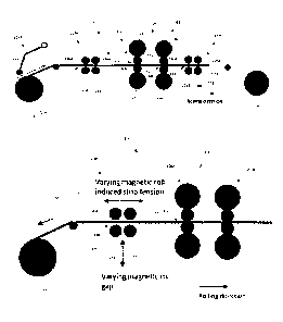
WO 2018/064218 PCT/1JS2017/053810
2
between rolls and the strip. These rolls are typically pinch rolls, bridle
rolls, or rolling
work rolls. However, the contact between the strip and the rolls, as well as
the
excessive strip tension from recoiling and deooiling operations, may cause
damage
such as scratching or other defects to the metal strip.
SUM MARY
[0005] The terms "invention," "the invention," "this invention" and "the
present invention"
used in this patent are intended to refer broadly to all of the subject matter
of this patent
and the patent claims below. Statements containing these terms should be
understood
not to limit the subject matter described herein or to limit the meaning or
scope of the
patent claims below. Embodiments of the invention covered by this patent are
defined
by the claims below, not this summary. This summary is a high-level overview
of various
embodiments of the invention and introduces some of the concepts that are
further
described in the Detailed Description section below. This summary is not
intended to
identify key or essential features of the claimed subject matter, nor is it
intended to be
used in isolation to determine the scope of the claimed subject matter. The
subject
matter should be understood by reference to appropriate portions of the entire
specification of this patent, any or all drawings, and each claim.
[0006] According to certain examples, a method of processing a metal strip
includes
passing the metal strip adjacent a magnetic rotor and tensioning the metal
strip through
the magnetic rotor. In various examples, the magnetic rotor is spaced apart
from the
metal strip by a first distance. In some examples, tensioning the metal strip
through the
magnetic rotor includes rotating the magnetic rotor to induce a magnetic field
into the
metal strip such that the metal strip is tensioned in an upstream direction or
a
downstream direction.
(0007] According to various examples, a system for non-contact tensioning of a
metal
strip during metal processing is also provided. In some examples, the system
includes a
magnetic tensioner with at least one magnetic rotor. The magnetic rotor is
spaced apart
from a passline of a metal strip such that, during metal processing, the
magnetic rotor is
a distance from the metal strip. The magnetic rotor is selectively rotatable
in a forward
CA 03037755 2019-03-20
WO 2018/064218 PCT/1JS2017/053810
3
direction and a reverse direction such that the magnetic rotor induces a
magnetic field
into the metal strip and tensions the metal strip in an upstream direction or
a
downstream direction. In various examples, the magnetic rotor is vertically
adjustable
such that a distance between the magnetic rotor and the metal strip is
adjusted. In
certain examples, vertically adjusting the distance between the magnetic rotor
and the
metal strip adjusts the amount of tension acting on the metal strip from the
magnetic
rotor. In other examples, a rotational speed of the magnetic rotor may be
adjusted to
adjust the amount of tension acting on the metal strip from the magnetic
rotor.
(00013] According to certain examples, a method of processing a metal strip
includes
passing the metal strip adjacent a magnetic rotor while passing the metal
strip from a
coil of the metal strip supported on an unwind coiler to a first work stand of
a metal
processing line downstream from the unwind coiler. In some examples, the
magnetic
rotor is spaced apart from the metal strip by a first distance. In various
examples, the
method also includes rotating the magnetic rotor to induce a magnetic field
into the
metal strip such that the metal strip is tensioned in an upstream direction or
a
downstream direction between the unwind coiler and the first work stand.
(0009] According to some examples, a method of processing a metal strip
includes:
passing the metal strip adjacent a magnetic rotor, detecting a first unwind
tension in the
metal strip downstream from the magnetic rotor, and detecting a second unwind
tension
in the metal strip upstream from the magnetic rotor. In some examples, the
magnetic
rotor is spaced apart from the metal strip by a first distance. In various
examples, the
method includes rotating the magnetic rotor to induce a magnetic field into
the metal
strip such that the metal strip is tensioned in an upstream direction or a
downstream
direction and a tension from the magnetic rotor reduces the second unwind
tension
while maintaining the first unwind tension.
[0010]According to various examples, a method of processing a metal strip
includes
passing the metal strip adjacent a magnetic rotor while passing the metal
strip from a
last work stand of a metal processing line to a rewind coiler downstream from
the last
work stand. In certain cases, the magnetic rotor is spaced apart from the
metal strip by
a first distance. In some examples, the method includes rotating the magnetic
rotor to
CA 03037755 2019-03-20
WO 2018/064218 PCT/1JS2017/053810
4
induce a magnetic field into the metal strip such that the metal strip is
tensioned in an
upstream direction or a downstream direction between the last work stand and
the
rewind coiler.
(0011] Various implementations described in the present disclosure can include
additional systems, methods, features, and advantages, which cannot
necessarily be
expressly disclosed herein but will be apparent to one of ordinary skill in
the art upon
examination of the following detailed description and accompanying drawings.
It is
intended that all such systems, methods, features, and advantages be included
within
the present disclosure and protected by the accompanying claims.
BRIEF DESCRIPTION OF THE DRAWINGS
[00121 The features and components of the following figures are illustrated to
emphasize the general principles of the present disclosure. Corresponding
features and
components throughout the figures can be designated by matching reference
characters for the sake of consistency and clarity.
W13] FIG. -I is a schematic of a metal processing system according to aspects
of the
current disclosure.
(0014] FIG. 2 is a schematic of a portion of the metal processing system of
FIG. 1.
(0015FIG. 3 is a schematic of another portion of the metal processing system
of
FIG. 1.
[0016] FIG. 4 is a schematic of another portion of the metal processing system
of
FIG. 1.
(0017FIG. 5 is a schematic of another portion of the metal processing system
of
FIG. 1.
(00183 FIG. 6 is a schematic of another portion of the metal processing system
of
FIG. 1.
[0019] FIG. 7 is a schematic of another portion of the metal processing system
of
FIG. 1.
CA 03037755 2019-03-20
WO 2018/064218 PCT/1JS2017/053810
[0020] FIG. 8 is a schematic of another portion of the metal processing system
of
FIG. 1.
DETAILED DESCRIPTION
[0021] The subject matter of examples of the present invention is described
here with
specificity to meet statutory requirements, but this description is not
necessarily
intended to limit the scope of the claims. The claimed subject matter may be
embodied
in other ways, may include different elements or steps, and may be used in
conjunction
with other existing or future technologies. This description should not be
interpreted as
implying any particular order or arrangement among or between various steps or
elements except when the order of individual steps or arrangement of elements
is
explicitly described.
[0022] Disclosed are systems and methods for non-contact tensioning of a metal
strip
during various stages of metal processing, including, but not limited to,
unwinding a coil
of the metal strip, threading the metal strip to a processing line, processing
the metal
strip with the processing line (e.g., rolling, slitting, leveling, and/or heat
treating the
metal strip), and rewinding the metal strip into a coil. Aspects and features
of the
present disclosure can be used with various suitable metal strips, and may be
especially
useful with metal strips of aluminum or aluminum alloys. Specifically,
desirable results
can be achieved when the metal strips are alloys such as 2xxx series, 3)ocx
series, 4x)oc
series, 5xxx series, 6xxx series, 7xxx series, or 8xxx series aluminum alloys.
For an
understanding of the number designation system most commonly used in naming
and
identifying aluminum and its alloys, see "International Alloy Designations and
Chemical
Composition Limits for Wrought Aluminum and Wrought Aluminum Alloys" or
"Registration Record of Aluminum Association Alloy Designations and Chemical
Compositions Limits for Aluminum Alloys in the Form of Castings and Ingot,"
both
published by The Aluminum Association.
[0023] In some cases, the systems and methods disclosed herein may be used
with
non-ferrous materials, including aluminum, aluminum alloys, magnesium,
magnesium-
based materials, titanium, titanium-based materials, copper, copper-based
materials,
CA 03037755 2019-03-20
WO 2018/064218 PCT/1JS2017/053810
6
steel, steel-based materials, bronze, bronze-based materials, brass, brass-
based
materials, composites, sheets used in composites, or any other suitable metal,
non-
metal or combination of materials. The article may include monolithic
materials, as well
as non-monolithic materials such as roll-bonded materials, clad materials,
composite
materials (such as but not limited to carbon fiber-containing materials), or
various other
materials. In one non-limiting example, the systems and methods can be used to
heat
metal articles such as aluminum metal strips, slabs, blanks, or other articles
made from
aluminum alloys, including aluminum alloys containing iron.
[0024] As used herein, the terms "above," "below," "vertical," and
"horizontal" are used
to describe relative orientations with respect to a metal strip or substrate
as if the metal
strip were moving in a horizontal direction with its top and bottom surfaces
generally
parallel to the ground. The term "vertical" as used herein can refer to a
direction
perpendicular to a surface (e.g., top or bottom surface) of the metal strip,
regardless of
the orientation of the metal strip. The term "horizontal" as used herein can
refer to a
direction parallel to a surface (e.g., top or bottom surface) of the metal
strip, such as a
direction parallel to the direction of travel of a moving metal strip,
regardless of the
orientation of the metal strip. The terms "above" and "below" can refer to
locations
beyond top or bottom surfaces of a metal strip, regardless of the orientation
of the metal
strip.
[0026] An example of a tensioning system 100 for non-contact tensioning of a
metal
strip 102 during metal processing is illustrated in FIG. 1. In various
examples, the
tensioning system 100 may be used with a processing line. In some examples and
as
illustrated in FIG. 1, the processing line includes a rolling mill 104,
although various
other metal processing equipment may be provided with the processing line in
addition
to or in place of the rolling mill 104.
[0026] In various cases, the rolling mill 104 includes at least one work stand
106. In
some examples, the rolling mill 104 includes a single work stand 106 or a
plurality of
work stands 106, such as two work stands 106, three work stands 106, four work
stands
106, five work stands 106, or any other desired number of work stands 106. In
the
example illustrated in FIG. 1, the rolling mill 104 includes two work stands
106 (a first
CA 03037755 2019-03-20
WO 2018/064218 PCT/1JS2017/053810
7
work stand 106A and a second work stand 106B). Each work stand 106A-B includes
a
pair of vertically aligned work rolls 108. In some examples, the work stands
106A-B also
include backup rolls 110 that support the work rolls 108. In various examples,
the work
stands 106A-B also include intermediate rolls. A roll gap 112 is defined
between the
work rolls 108 of each work stand 106A-B.
[0027] During processing, the metal strip 102 is passed through the roll gap
112 such
that the work rolls 108 reduce the thickness of the metal strip 102 to a
desired thickness
and impart particular properties on the metal strip 102. The particular
properties
imparted may depend on the composition of the metal strip 102. In some
examples, the
rolling mill 104 may be a hot rolling mill that is configured to roll the
metal strip 102 when
the temperature of the metal strip 102 is above the recrystallization
temperature of the
metal strip 102. In other examples, the rolling mill 104 may be a cold rolling
mill that is
configured to roll the metal strip 102 when the temperature of the metal strip
102 is
below the recrystallization temperature of the metal strip 102. In various
other
examples, the rolling mill 104 may be a warm rolling mill that is configured
to roll the
metal strip 102 when the temperature of the metal strip 102 is below the
recrystallization
temperature but above the temperature during cold rolling.
[0028] In some examples, the system 100 includes an unwind coiler 114 and a
rewind
coiler 116. During metal processing, the unwind coiler 114 supports a coil 118
of the
metal strip 102 and unwinds the metal strip 102 for processing by the
processing line. In
some examples, after being processed by the processing line, the rewind coiler
116
rewinds the metal strip 102.
[0029] During some stages of metal processing, portions of the metal strip 102
such as
portions near a leading edge 120 and/or portions near a trailing edge 122 (see
FIG. 7)
of the metal strip 102 may be contacted by various pieces of equipment. For
example,
traditionally, the metal strip 102 may be contacted by rolls during threading,
rewinding,
and tailing-out of the metal strip 102 among others. This contact may cause
surface
damage in the metal strip 102, which may damage and/or decrease the quality of
those
portions of the metal strip 102. Many times, these damaged portions are
unsuitable for
consumer needs and are discarded.
CA 03037755 2019-03-20
WO 2018/064218 PCT/1JS2017/053810
8
[0030] In addition to surface damage during metal processing, various tension
defects
including, but not limited to, thickness variations and/or shape variations in
the metal
strip 102 may also be imparted into the metal strip 102 during metal
processing due to
various factors. For example, in some cases, the unwind miler 114 and/or the
rewind
coiler 116 may not be perfectly cylindrical (e.g., they may be cam-shaped or
various
other shapes), and as the coilers 114, 116 rotate to unwind or rewind the
metal strip
102, the shape of the coilers 114, 116 causes tension variations in the metal
strip 102.
These tension variations may result in various tension-induced defects in the
metal strip
102. The metal strip 102 may be especially prone to tension-induced defects if
the metal
strip is a hot, surface-sensitive strip 102.
[0031] In various examples, to minimize surface damage and tension defects in
the
metal strip 102 (and thereby produce a metal strip 102 with improved quality),
the
tensioning system 100 includes at least one magnetic tensioner 124 that is
configured
to impart tension forces in the metal strip 102 during metal processing
without
contacting the metal strip 102. By imparting tension forces in the metal strip
102, the
magnetic tensioner 124 may control the tension in the metal strip 102 at
various
locations along the metal strip 102 and guide or position the metal strip 102
while
minimizing surface damage or other defects in the metal strip 102 as described
in detail
below.
[0032] In the non-limiting example illustrated in FIG. 1. the system 100
includes three
magnetic tensioners 124A-C. In this example, the magnetic tensioner 124A is
positioned proximate to the unwind coiler 114, the magnetic tensioner 124B is
positioned between the unwind coiler 114 and the rolling mill 104 (or
processing line),
and the magnetic tensioner 124C is positioned between the rolling mill 104 and
the
rewind coiler 116. In various other examples, any desired number of magnetic
tensioners 124 may be provided at various locations as desired. For example,
in some
cases, the magnetic tensioner 124A may be omitted. In other examples, only the
magnetic tensioner 124B or the magnetic tensioner 124C may be included. In
various
other examples, magnetic tensioners 124 in addition to or in place of the
magnetic
tensioners 124A-C may be provided at various other locations along the path of
the
metal strip 102 where tension control and/or guiding of the metal strip 102
may be
CA 03037755 2019-03-20
WO 2018/064218 PCT/1JS2017/053810
9
desirable. As such, the number and location of magnetic tensioners 124 should
not be
considered limiting on the current disclosure.
[0033] Each magnetic tensioner 124A-C includes at least one magnetic rotor
126. As
described in detail below, in some examples, the magnetic tensioners 124A-C
may
include more than one magnetic rotor 126. For example, each magnetic tensioner
124A-C may include one magnetic rotor 126, two magnetic rotors 126, three
magnetic
rotors 126, four magnetic rotors 126, five magnetic rotors 126, six magnetic
rotors 126,
or more than six magnetic rotors 126. In various examples, the number of
magnetic
rotors 126 included with each magnetic tensioner 124A-C need not be the same,
although two or more of the magnetic tensioners 124A-C can have the same
number of
magnetic rotors 126 in other examples. The magnetic rotors 126 are spaced
apart from
the passline of the metal strip 102 such that, during metal processing, the
magnetic
rotors 126 are in a non-contacting configuration with the metal strip 102. In
various
examples, the magnetic rotors 126 are vertically adjustable such that a
distance
between a particular magnetic rotor 126 and the metal strip 102 may be varied.
[0 0 34] Each magnetic rotor 126 includes one or more permanent magnets or
electromagnets. The magnetic rotors 126 are rotatable in a forward direction
(a
clockwise direction in FIG. 1) or a reverse direction (a counter-clockwise
direction in
FIG. 1). In various examples, the magnetic rotors 126 may be rotated through
various
suitable methods including, but not limited to, electric motors, pneumatic
motors,
another magnetic rotor, or various other suitable mechanisms. In various
examples, the
magnetic rotors 126 may change their direction of rotation during processing.
The
magnetic rotors 126 may rotate at various rotational speeds, such as from
about 100
rpm to about 5000 rpm. In one non-limiting example, the magnetic rotors 126
rotate at
about 1800 revolutions per minute, although various other rotational speeds
may be
utilized. As the magnetic rotors 126 rotate, the magnets induce a magnetic
field into the
metal strip 102 such that the metal strip 102 is tensioned in an upstream
direction or a
downstream direction. In various examples, the magnetic rotors 126 are
configured to
induce a magnetic field that imparts tangential tension forces that are
greater than radial
tension forces. For example, in some cases, the ratio of tangential tension
forces to
radial tension forces may be from about 1:10 to about 10:1. In some examples,
in
CA 03037755 2019-03-20
WO 2018/064218 PCT/1JS2017/053810
addition to tensioning the metal strip 102, rotating the magnetic rotors 126
may also
provide vertical stabilization that allows the metal strip 102 to pass over
and/or between
the magnetic rotors 126 without contacting the magnetic rotors 126 (e.g., the
magnetic
rotors 126 levitate or float the metal strip 102). For example, in some cases,
the
magnetic rotors 126 impart a force that is perpendicular or substantially
perpendicular to
a surface of the metal strip 102 to float the metal strip 102 and minimize
and/or
eliminate contact between the rotors 126 and the metal strip 102.
(0035] In some examples, the magnetic tensioner 124A is a hold down roll that
includes
one or more magnetic rotors 126. In various cases, the magnetic tensioner 1248
may
be between the unwind miler 114 and the rolling mill 104 to guide and control
tension in
the metal strip 102 upstream of the rolling mill 104. In a similar manner, the
magnetic
tensioner 124C may be between the rolling mill 104 and the rewind coiler 116
to guide
and control tension in the metal strip 102 downstream of the rolling mill 104.
(00361 As illustrated in FIG. 1, in some examples, the magnetic tensioner 124B
and/or
the magnetic tensioner 124C includes a set of magnetic rotors having a top
magnetic
rotor 126A and a bottom magnetic rotor 126B. In other examples, the magnetic
tensioner 1248 and/or the magnetic tensioner 124C includes only a bottom
magnetic
rotor 1268, only a top magnetic rotor 126A, or various combinations of top
magnetic
rotors 126A and bottom magnetic rotors 1268. In certain examples, the magnetic
tensioner 1248 and/or the magnetic tensioner 124C includes a plurality of sets
of
magnetic rotors. As such, the number of sets of magnetic rotors should not be
considered limiting on the current disclosure. In some cases, the top magnetic
rotor
126A is vertically offset from the bottom magnetic rotor 126B such that a gap
128 is
defined between the rotors 126A-B. As illustrated in FIG. 1, during
processing, the metal
strip 102 is passed through the gap 128. In other examples, the top magnetic
rotor 126A
may be horizontally offset from the bottom magnetic rotor 1268 such that the
magnetic
rotors 126A-B are not vertically aligned.
[0037] In various examples, the top magnetic rotor 126A and the bottom
magnetic rotor
1268 are vertically adjustable such that a size of the gap 128, which is a
distance from
the top magnetic rotor 126A to the bottom magnetic rotor 126B, may be varied.
In
CA 03037755 2019-03-20
WO 2018/064218 PCT/1JS2017/053810
11
various examples, the gap 128 of the magnetic rotors 126A-B may be controlled
through various actuators including, but not limited to hydraulic pistons,
screw drives, or
other suitable actuators. In certain examples, the gap 128 may be varied
between a
minimum gap size and a maximum gap size. In some examples, the magnitude of
the
tension force imparted by the magnetic rotors 126A-B into the metal strip 102
may be
maximized when the distance between the metal strip 102 and the magnetic
rotors
126A-B is minimized. Conversely, the magnitude of the tension force imparted
by the
magnetic rotors 126A-B may be minimized when the distance between the metal
strip
102 and the magnetic rotors 126A-8 is maximized. The top magnetic rotor 126A
may be
vertically adjustable independent from or in conjunction with the bottom
magnetic rotor
126B. In some examples, the top magnetic rotor 126A and the bottom magnetic
rotor
1268 rotate in the same direction, although they need not. For example, in
some cases,
the top magnetic rotor 126A and the bottom magnetic rotor 126B may rotate in
opposite
directions. In various examples, the magnetic rotors 126A-B of one set of
magnetic
rotors may rotate in the same or in a different direction as the corresponding
magnetic
rotors 126A-B of another set of magnetic rotors. In various examples, a
configuration of
the magnetic rotors 126 in the magnetic tensioner 1248 may be the same or may
be
different from the configuration of the magnetic rotors 126 in the magnetic
tensioner
124C.
[0038] In certain examples, the tensioning system 100 includes various sensors
or
monitors at various positions along the path of the metal strip 102. These
sensors may
detect and monitor the position of the metal strip 102, the tension in the
metal strip 102
at the location of the sensor, the thickness profile of the metal strip 102 at
the location of
the sensor, the temperature in the metal strip 102 at the location of the
sensor, and/or
various other information about the metal strip 102 as it is processed. In
some
examples, the information gathered by the sensors may be used by a controller
to
adjust the magnetic rotors 126 (e.g., rotational speed, direction of rotation,
distance
from metal strip 102, etc.) and thereby control the metal strip 102.
[0039] FIGS. 2-7 illustrate non-limiting examples of methods of controlling
tension
and/or guiding the metal strip 102 with the magnetic tensioners 124A-C. The
illustrated
methods may be used alone or in various combinations as desired.
CA 03037755 2019-03-20
WO 2018/064218 PCT/1JS2017/053810
12
[0040] FIG. 2 illustrates a non-limiting example of a threading process using
the
magnetic tensioner 124A. In some examples, the method includes threading the
metal
strip 102 with minimal or no contact between the magnetic rotors 126 and the
metal
strip 102. In various examples, the method of threading the metal strip 102
with the
magnetic tensioner 124A indudes receiving the coil 118 of the metal strip 102
on the
unwind coiler 114 and adjusting the magnetic tensioner 124A such that the
magnetic
rotor 126 of the magnetic tensioner 124A is separated from the metal strip 102
by a
predetermined distance. In various cases, the method includes positioning the
magnetic
rotor 126 of the magnetic tensioner 124A proximate to an unroll point 130
wherein the
metal strip 102 is unwound from the coil 118. In some examples, a weld
securing the
leading edge 120 of the metal strip 102 to the coil 118 may be broken prior to
unwinding
and threading the metal strip 102.
[0041] In various cases, the method includes rotating the magnetic rotor 126
such that a
radial tension force (or a "hold down force") is applied to the strip to
minimize or
eliminate relative motion and clock springing of the outer lap of the metal
strip 102 to the
coil 118. The hold down force may be beneficial during the threading process
(and if
strip tension is not established in the line) to avoid scratches and clock
springing. In
some examples, the magnetic rotor 126 of the magnetic tensioner 124A imparts a
tension force 132 such that it is greater in the tangential direction than in
the radial
direction, although it need not. In some examples, the magnetic rotor 126 of
the
magnetic tensioner 124A continues to impart the tension force 132 and/or hold
down
force in the metal strip 102 until the leading edge 120 is threaded into the
roll gap 112 of
the work stand 106A. In other examples, the magnetic rotor 126 may continue to
impart
the tension force 132 and/or hold down force into the metal strip 102 after
the leading
edge 120 is threaded into the roll gap 112.
[0042] In some cases. the method also includes rotating the magnetic rotor 126
such
that the tension force 132 is imparted into the metal strip 102 that advances
the metal
strip 102 downstream. In some examples, the tension imparted by the magnetic
tensioner 124A advances the metal strip 102 to guide the leading edge 120 of
the metal
strip 102 into the roll gap 112. In other examples, the tension imparted from
the
magnetic tensioner 124A may also advance the metal strip 102 after the leading
edge
CA 03037755 2019-03-20
WO 2018/064218 PCT/1JS2017/053810
13
120 of the metal strip 102 is threaded into the roll gap 112. In certain
examples, the
magnetic rotor 126 of the magnetic tensioner 124A is rotated in the reverse
direction to
impart the tension force 132 in the metal strip 102. In various examples, the
tension
force 132 may be from about 0.5 MPa to about 50 MPa. In various cases, the
magnitude of the tension force 132 is controlled by vertically adjusting the
magnetic
rotor 126 to increase or decrease the distance between the magnetic rotor 126
and the
metal strip 102. The magnitude of the tension force 132 may also be controlled
by
adjusting the rotational speed of the magnetic rotor 126 and/or the direction
of rotation
of the magnetic rotor 126.
[0043] FIG. 3 illustrates a non-limiting example of a threading process using
the
magnetic tensioner 1248. In some examples, the method includes threading the
metal
strip 102 with minimal or no contact between the magnetic rotors 126A-B and
the metal
strip 102. In various examples, the threading process illustrated in FIG. 3
may be used
in conjunction with or in place of the threading process illustrated in FIG.
2.
[0044] In the method illustrated in FIG. 3, the metal strip 102 is passed
through the gap
128 between the top magnetic rotor 126A and the bottom magnetic rotor 126B.
The top
magnetic rotor 126A and the bottom magnetic rotor 1268 are rotated such that a
tension force 134 is imparted into the metal strip 102 that advances the metal
strip 102
downstream. In some examples, the top magnetic rotor 126A is rotated in the
reverse
direction and the bottom magnetic rotor 1268 is rotated in the forward
direction to impart
the tension force 134, or vice versa. In various examples, the tension force
134 applied
by a single pair of rotors may be from about 0.5 MPa to about 50 MPa depending
on the
gap 128, the rotational speed, the strip thickness, the number of rotors, and
the design
of the rotors, among other factors. In various examples, the magnitude of the
tension
force 134 may be controlled by changing the size of the gap 128, the
rotational speed of
the magnetic rotors 126A-B, and/or the direction of rotation of the magnetic
rotors 126A-
B. In some examples, applying the tension force 134 at intermediate points
along the
path of the metal strip 102 between the unwind coiler 114 and the rolling mill
104
improves the ability to steer and center the leading edge 120 of the metal
strip 102 into
the roll gap 112 of the first work stand 106A. In some examples, the magnetic
rotors
126A-B of the magnetic tensioner 124B continue to impart the tension force 134
in the
CA 03037755 2019-03-20
WO 2018/064218 PCT/1JS2017/053810
14
metal strip 102 until the leading edge 120 is threaded into the roll gap 112
of the work
stand 106A. In other examples, the magnetic rotors 126A-B may continue to
impart the
tension force 134 into the metal strip 102 after the leading edge 120 is
threaded into the
roll gap 112. In other examples, the magnetic rotors 126A-B may reverse the
tension
force 134 into the metal strip 102 after the leading edge 120 is threaded into
the roll gap
112.
(0045] FIG. 4 illustrates a non-limiting example of a method of controlling
strip tension
force 136 at the roll gap 112 with the magnetic tensioner 124B. In other
examples,
controlling the strip tension force 136 may occur at various other locations
upstream
from the magnetic tensioner 124B. In some examples, the method includes
controlling
the strip tension force 136 with minimal or no contact between the magnetic
rotors
126A-B and the metal strip 102. In various examples, the method illustrated in
FIG. 4
may optionally be used in conjunction with the threading process of FIG. 2
and/or FIG.
3. In some examples, the method includes imparting a second tension force 140
after
threading the metal strip with the method illustrated in FIG. 2 and/or FIG. 3.
In such
cases, the method includes changing the direction of rotation of at least some
of the
magnetic rotors 126A-8 from the direction of rotation in FIG. 3.
(0046] Traditionally, the strip tension force 136 at the roll gap 112 is
controlled by the
unwind tension force 138 induced in the metal strip 102 by the unwind coiler
114.
However, controlling the strip tension force 136 through the unwind coiler 114
may
cause variations in tension in the metal strip 102 because the unwind coiler
114 may not
be perfectly cylindrical as described above. In addition, controlling the
strip tension force
136 through the unwind coiler 114 may cause surface damage due to movement of
the
metal strip 102 during unwinding.
(0047] Through the magnetic tensioner 1246, the method includes imparting the
second
tension force 140 into the metal strip 102. By imparting the second tension
force 140 at
an intermediate position between the unwind coiler 114 and the rolling mill
104, the
second tension force 140 and/or the unwind tension force 138 may be used to
control
the strip tension force 136 (i.e., the strip tension force 136 is a sum of the
unwind
tension force 138 and the second tension force 140). In various examples,
imparting the
CA 03037755 2019-03-20
WO 2018/064218 PCT/1152017/053810
second tension force 140 includes rotating the top magnetic rotor 126A and the
bottom
magnetic rotor 126B such that the metal strip 102 is tensioned in a direction
opposite a
rolling direction of the metal strip 102. In some examples, the top magnetic
rotor 126A is
rotated in the forward direction and the bottom magnetic rotor 126B is rotated
in the
reverse direction to impart the second tension force 140, or vice versa. In
various
examples, the second tension force 140 may be from about 0.5 MPa to about 50
MPa.
In various examples, the magnitude of the tension force 140 may be controlled
by
changing the size of the gap 128, the rotational speed of the magnetic rotors
126A-B,
and/or the direction of rotation of the magnetic rotors 126A-8. In some
examples where
multiple sets of magnetic rotors 126A-B are provided, the first set of
magnetic rotors
may rotate in a first configuration and a second set of magnetic rotors may
rotate in a
second configuration opposite of the first configuration to provide the
desired magnitude
of the second tension force 140.
[0048] In some examples, the method includes minimizing the unwind tension
force 138
by providing the second tension force 140. Minimizing the unwind tension force
138
may minimize damage or defects caused by the unwind caller 114 during
unwinding of
the metal strip 102 from the unwind coiler 114. In certain examples, the
second tension
force 140 is a replacement tension force for the unwind tension force 138. In
some
cases, the magnitude of the second tension force 140 is greater than or equal
to the
unwind tension force 138 such that the strip tension force 136 is maintained
or
controlled as desired while the unwind tension force 138 is minimized or
reduced.
[0049] Referring to FIG. 5, in some examples, the method includes modulating
the
unwind tension force 138 by adjusting the magnetic rotors 126A-B of the
magnetic
tensioner 124B. In some examples, the method includes modulating the unwind
tension
force 138 with minimal or no contact between the magnetic rotors 126A-B and
the metal
strip 102. In some examples, modulating the unwind tension force 138 includes
varying
the size of the gap 128. For example, in some cases, modulating the unwind
tension
force 138 includes rapidly moving the magnetic rotors 126A-B in the vertical
direction
such that the size of the gap 128 is varied to vary the magnitude of the
second tension
force 140. In various examples, modulating the unwind tension force 138
includes
varying a direction of the second tension force 140 by changing the direction
of rotation
CA 03037755 2019-03-20
WO 2018/064218 PCT/1JS2017/053810
16
of at least one of the magnetic rotors 126A-B. In certain examples, modulating
the
unwind tension form 138 includes varying a rotational speed of the at least
one of the
magnetic rotors 126A-B. In certain examples, modulating the unwind tension
force 138
includes varying a distance between adjacent top magnetic rotors 126A or
adjacent
bottom magnetic rotors 126B in a longitudinal direction. Various other
adjustments to
the magnetic rotors 126A-B may be used to modulate or change the magnetic
rotors
126A-B and thus the unwind tension force 138. By modulating the unwind tension
force
138, the magnetic tensioner 124B can offset unwind coil-induced disturbances
and
therefore reduce wrap-to-wrap damage at the coil and thickness variations or
disturbances.
[0050] FIG. 6 illustrates a non-limiting example of a method of guiding the
metal strip
102 from the rolling mill 104 to the rewind coiler 116 with the magnetic
tensioner 124C.
In some examples, the method includes guiding the metal strip 102 with minimal
or no
contact between the magnetic rotors 126A-B and the metal strip 102.
(0051] In some examples, similar to the method illustrated in FIG. 3, the
method
includes rotating the top magnetic rotor 126A and the bottom magnetic rotor
126B of the
magnetic tensioner 124C such that an unwind tension force 142 is imparted into
the
metal strip that advances the metal strip 102 downstream. In some examples,
the top
magnetic rotor 126A is rotated in the reverse direction and the bottom
magnetic rotor
126B is rotated in the forward direction to impart the unwind tension force
142, or vice
versa. In various examples, the unwind tension force 142 may be from about 0.5
MPa to
about 50 MPa. In various examples, the magnitude of the unwind tension force
142 may
be controlled by changing the size of the gap 128, the rotational speed of the
magnetic
rotors 126A-B, and/or the direction of rotation of the magnetic rotors 126A-B.
In some
examples, applying the unwind tension force 142 at intermediate points along
the path
of the metal strip 102 between the rolling mill 104 and the rewind coiler 116
improves
the ability to steer and center the leading edge 120 of the metal strip 102
towards the
center of the rewind coiler 116 such that the metal strip 102 is centered
while it is
rewound.
CA 03037755 2019-03-20
WO 2018/064218 PCT/1JS2017/053810
17
[0052] In various examples, the magnetic rotors 126A-B of the magnetic
tensioner 124C
are configured to impart the unwind tension force 142 that is greater in the
tangential
direction than in the radial direction such that the unwind tension force 142
advances
the metal strip 102 towards the rewind coiler 116. In some examples, the
magnetic
rotors 126A-B of the magnetic tensioner 124C continue to impart the unwind
tension
force 142 in the metal strip 102 until the leading edge 120 is positioned on
the rewind
coiler 116 and/or the tension is established on the rewind coiler 116. In
other examples,
the magnetic rotors 126A-B may continue to impart the unwind tension force 142
into
the metal strip 102 after the leading edge 120 is positioned on the rewind
coiler 116.
[0053] In some examples, the method includes modulating a rewind tension force
imparted into the metal strip 102 by the rewind coiler 116 while rewinding the
metal strip
102 on the rewind coiler 116. Similar to the method illustrated in FIG. 5,
modulating the
rewind tension force includes varying the size of the gap 128, varying a
direction of the
unwind tension force 142, and/or varying a rotational speed of at least one of
the
magnetic rotors 126A-B. By modulating the unwind tension force 142, the
magnetic
tensioner 124C can offset unwind coil-induced disturbances and therefore
reduce wrap-
to-wrap damage at the rewind coil and thickness variations or disturbances.
[0054] FIG. 7 illustrates a non-limiting example of a method of guiding the
trailing edge
122 of the metal strip 102 with the magnetic tensioner 124B during tailing-out
from the
unwind coiler 114. During tailing-out from the unwind coiler 114, the metal
strip 102 has
unwrapped from the unwind coiler 114, and the unwind coiler 114 no longer
provides
the unwind tension force 138. To keep the unwind tension and the metal strip
102
centered as the trailing edge 122 moves towards the rolling mill 104, the
method
includes rotating the magnetic rotors 126A-B of the magnetic tensioner 124B
such that
a tension force 144 is applied in the reverse direction, or away from the
rolling mill 104.
In various examples, the magnitude of the tension force 144 may be controlled
by
changing the size of the gap 128, the rotational speed of the magnetic rotors
126A-B,
and/or the direction of rotation of the magnetic rotors 126A-B. In some
examples,
applying the tension force 144 at intermediate points along the path of the
metal strip
102 between the unwind coiler 114 and the rolling mill 104 improves the
ability to steer
CA 03037755 2019-03-20
WO 2018/064218 PCT/1JS2017/053810
18
and center the trailing edge 122 of the metal strip 102 into the roll gap 112
of the first
work stand 106A.
[0055] FIG. 8 illustrates a non-limiting example of a method of guiding the
trailing edge
122 with the magnetic tensioner 124C during tailing-out from the rolling mill
104. During
tailing-out from the rolling mill 104, the metal strip 102 has exited the
rolling mill 104,
and the rolling mill 104 no longer provides a tension force on the metal strip
102. To
keep the recoiling strip tension and the metal strip 102 centered as the
trailing edge 122
moves towards the rewind coiler 116, the method includes rotating the magnetic
rotors
126A-B of the magnetic tensioner 124C such that a tension force 146 is applied
in the
reverse direction, or away from the rewind coiler 116. In various examples,
the
magnitude of the tension force 146 may be controlled by changing the size of
the gap
128, the rotational speed of the magnetic rotors 126A-B, and/or the direction
of rotation
of the magnetic rotors 126A-B. In some examples, applying the tension force
146 at
intermediate points along the path of the metal strip 102 between the rolling
mill 104
and the rewind coiler 116 improves the ability to steer and center the
trailing edge 122
of the metal strip 102 onto the rewind caller 116.
(0056]A collection of exemplary embodiments, including at least some
explicitly
enumerated as "ECs" (Example Combinations), providing additional description
of a
variety of embodiment types in accordance with the concepts described herein
are
provided below. These examples are not meant to be mutually exclusive,
exhaustive, or
restrictive; and the invention is not limited to these example embodiments but
rather
encompasses all possible modifications and variations within the scope of the
issued
claims and their equivalents.
[0057] EC 1. A method of processing a metal strip comprising: passing the
metal strip
adjacent a magnetic rotor, wherein the magnetic rotor is spaced apart from the
metal
strip by a first distance; and rotating the magnetic rotor to induce a
magnetic field into
the metal strip such that the metal strip is tensioned in an upstream
direction or a
downstream direction.
[0068] EC 2. The method of any of the preceding or subsequent example
combinations,
wherein passing the metal strip adjacent the magnetic rotor comprises passing
the
CA 03037755 2019-03-20
WO 2018/064218 PCT/1JS2017/053810
19
metal strip from a coil of the metal strip supported on an unwind coiler to a
first work
stand of a metal processing line downstream from the unwind collar, and
wherein
tensioning the metal strip through the magnetic rotor comprises tensioning the
metal
strip between the unwind coiler and the first work stand.
[0059] EC 3. The method of any of the preceding or subsequent example
combinations,
wherein the magnetic rotor is a top magnetic rotor of a set of magnetic rotors
comprising
the top magnetic rotor and a bottom magnetic rotor vertically offset from the
top
magnetic rotor by a gap, wherein passing the metal strip adjacent the magnetic
rotor
comprises passing the metal strip through the gap, and wherein tensioning the
metal
strip comprises rotating the top magnetic rotor and the bottom magnetic rotor
to induce
the magnetic field into the metal strip such that the metal strip is
tensioned.
[0060] EC 4. The method of any of the preceding or subsequent example
combinations,
wherein the top magnetic rotor and the bottom magnetic rotor are horizontally
offset.
[0061] EC 5. The method of any of the preceding or subsequent example
combinations,
further comprising guiding a leading edge of the metal strip to a roll gap of
the first work
stand by tensioning the metal strip in the downstream direction.
[0062] EC 6. The method of any of the preceding or subsequent example
combinations,
wherein guiding the leading edge of the metal strip comprises centering the
leading
edge of the metal strip within the roll gap.
[0063] EC 7. The method of any of the preceding or subsequent example
combinations,
further comprising guiding a trailing edge of the metal strip to a roll gap of
the first work
stand by tensioning the metal strip in the upstream direction after the
trailing edge has
been unwrapped from the unwind coiler.
[0064] EC 8. The method of any of the preceding or subsequent example
combinations,
wherein guiding the trailing edge of the metal strip comprises centering the
trailing edge
of the metal strip within the roll gap.
[0065] EC 9. The method of any of the preceding or subsequent example
combinations,
further comprising: detecting a first unwind tension in the metal strip
downstream from
the magnetic rotor; detecting a second unwind tension in the metal strip
upstream from
CA 03037755 2019-03-20
WO 2018/064218 PCT/1JS2017/053810
the magnetic rotor; and tensioning the metal strip through the magnetic rotor
such that a
tension from the magnetic rotor reduces the second unwind tension while
maintaining
the first unwind tension.
(0066] EC 10. The method of any of the preceding or subsequent example
combinations, wherein the first unwind tension is detected at a roll gap of
the first work
stand and the second unwind tension is detected at an unroll point of the
metal strip
from the unwind coiler.
(0067] EC 11. The method of any of the preceding or subsequent example
combinations, further comprising: determining a tension at the unwind coiler;
determining the tension added by the magnetic rotor; and calculating the
tension at an
entry of the work stand by summing the tension at the unwind coiler and the
tension
added by the magnetic rotor.
(0068] EC 12. The method of any of the preceding or subsequent example
combinations, further comprising modulating the tension from the magnetic
rotor by
vertically adjusting the magnetic rotor relative to the metal strip to adjust
the first
distance.
[0069] EC 13. The method of any of the preceding or subsequent example
combinations, further comprising modulating the tension from the magnetic
rotor by
adjusting a rotational speed of the magnetic rotor.
[0070] EC 14. The method of any of the preceding or subsequent example
combinations, wherein passing the metal strip adjacent the magnetic rotor
comprises
passing the metal strip from a last work stand of a metal processing line to a
rewind
coiler downstream from the last work stand, and wherein tensioning the metal
strip
through the magnetic rotor comprises tensioning the metal strip between the
last work
stand and the rewind coiler.
(0071 EC 15. The method of any of the preceding or subsequent example
combinations, wherein the magnetic rotor is a top magnetic rotor of a set of
magnetic
rotors comprising the top magnetic rotor and a bottom magnetic rotor
vertically offset
from the top magnetic rotor by a gap, wherein passing the metal strip adjacent
the
CA 03037755 2019-03-20
WO 2018/064218 PCT/1JS2017/053810
21
magnetic rotor comprises passing the metal strip through the gap, and wherein
tensioning the metal strip comprises rotating the top magnetic rotor and the
bottom
magnetic rotor to induce the magnetic field into the metal strip such that the
metal strip
is tensioned.
(0072] EC 16. The method of any of the preceding or subsequent example
combinations, wherein the top magnetic rotor and the bottom magnetic rotor are
horizontally offset.
[0073] EC 17. The method of any of the preceding or subsequent example
combinations, further comprising guiding a leading edge of the metal strip to
the rewind
coiler by tensioning the metal strip in the downstream direction.
(0074] EC 18. The method of any of the preceding or subsequent example
combinations, wherein guiding the leading edge comprises centering the metal
strip on
the rewind coiler.
(0075] EC 19. The method of any of the preceding or subsequent example
combinations, further comprising guiding a trailing edge of the metal strip to
the rewind
coiler by tensioning the metal strip in the upstream direction after the
trailing edge has
exited a roll gap of the last work stand.
[00763 EC 20. The method of any of the preceding or subsequent example
combinations, wherein guiding the trailing edge of the metal strip comprises
centering
the trailing edge of the metal strip within the roll gap.
(0077] EC 21. The method of any of the preceding or subsequent example
combinations, further comprising: detecting a first rewind tension in the
metal strip
downstream from the magnetic rotor; detecting a second rewind tension in the
metal
strip upstream from the magnetic rotor; and tensioning the metal strip through
the
magnetic rotor such that a tension from the magnetic rotor reduces the second
rewind
tension while maintaining the first rewind tension.
(0078] EC 22. The method of any of the preceding or subsequent example
combinations, further comprising: determining a tension at the rewind coiler;
determining the tension added by the magnetic rotor; and calculating the
tension at an
CA 03037755 2019-03-20
WO 2018/064218 PCT/1JS2017/053810
22
entry of the work stand by summing the tension at the rewind coiler and the
tension
added by the magnetic rotor.
[0079] EC 23. The method of any of the preceding or subsequent example
combinations, further comprising modulating the tension from the magnetic
rotor by
vertically adjusting the magnetic rotor relative to the metal strip to adjust
the first
distance.
(0080] EC 24. The method of any of the preceding or subsequent example
combinations, further comprising modulating the tension from the magnetic
rotor by
adjusting a rotational speed of the magnetic rotor.
[0081] EC 25. The method of any of the preceding or subsequent example
combinations, wherein the first distance is from about 1 mm to about 10 m.
[0082] EC 26. The method of any of the preceding or subsequent example
combinations, wherein the first distance is from about 1 mm to about 200 mm.
[0083] EC 27. The method of any of the preceding or subsequent example
combinations, wherein the metal strip is tensioned is from about 0.5 MPa to
about 50
MPa.
[00841 EC 28. The method of any of the preceding or subsequent example
combinations, wherein a rotational speed of the magnetic rotor is about 100
rpm to
about 5000 rpm.
[00851 EC 29. The method of any of the preceding or subsequent example
combinations, wherein the rotational speed is about 1800 rpm.
[0086] EC 30. A system for performing the method of any of the preceding or
subsequent example combinations, the system comprising the magnetic rotor,
wherein
the magnetic rotor is selectively rotatable in a forward direction and a
reverse direction,
and wherein the magnetic rotor is vertically adjustable such that the first
distance is
adjustable.
(0087] EC 31. A system for performing the method of any of the preceding or
subsequent example combinations, the system comprising a magnetic tensioner
comprising the magnetic rotor.
CA 03037755 2019-03-20
WO 2018/064218 PCT/1JS2017/053810
23
[0088] EC 32. The system of any of the preceding or subsequent example
combinations, wherein the magnetic rotor is a top magnetic rotor of the
magnetic
tensioner, wherein the magnetic tensioner further comprises a bottom magnetic
rotor
vertically offset from the top magnetic rotor, wherein the bottom magnetic
rotor and the
top magnetic rotor are selectively rotatable in a forward direction or a
reverse direction
to induce a magnetic field into the metal strip such that the metal strip is
tensioned, and
wherein a gap configured to receive the metal strip is defined between the top
magnetic
rotor and the bottom magnetic rotor.
[0089] EC 33. The system of any of the preceding or subsequent example
combinations, wherein the top magnetic rotor and the bottom magnetic rotor are
a first
set of magnetic rotors, and wherein the magnetic tensioner further comprises a
plurality
of sets of magnetic rotors.
[0090] EC 34. The system of any of the preceding or subsequent example
combinations, wherein the top magnetic rotor and the bottom magnetic rotor are
each
vertically adjustable such that a size of the gap is adjustable.
[0091] EC 35. The system of any of the preceding or subsequent example
combinations, further comprising: the unwind coiler; and the first work stand
of the metal
processing line.
[0092] EC 36. The system of any of the preceding or subsequent example
combinations, further comprising: a first sensor downstream from the magnetic
tensioner and configured to detect a first unwind tension in the metal strip;
a second
sensor upstream from the magnetic tensioner and configured to detect a second
unwind
tension in the metal strip; and a controller configured to rotate the magnetic
rotor such
that a tension from the magnetic rotor reduces the second unwind tension while
maintaining the first unwind tension.
[0093] EC 37. The system of any of the preceding or subsequent example
combinations, wherein the first sensor is configured to detect the first
unwind tension at
a roll gap of the first work stand, and wherein the second sensor is
configured to detect
the second unwind tension between the unwind coiler and the magnetic
tensioner.
CA 03037755 2019-03-20
WO 2018/064218 PCT/1JS2017/053810
24
[0094] EC 38. The system of any of the preceding or subsequent example
combinations, wherein the controller is configured to adjust at least one of a
rotational
speed of the magnetic rotor or the first distance to modulate the tension from
the
magnetic rotor.
[0095] EC 39. The system of any of the preceding or subsequent example
combinations, further comprising: a first sensor downstream from the magnetic
tensioner and configured to detect a first unwind tension in the metal strip;
a second
sensor at the magnetic tensioner and configured to detect an applied magnetic
tension
from the magnetic tensioner in the metal strip; and a controller configured to
rotate the
magnetic rotor to apply the tension from the magnetic rotor to control the
first unwind
tension.
[0096] EC 40. A system for performing the method of any of the preceding or
subsequent example combinations, the system comprising a magnetic tensioner
comprising the magnetic rotor.
[0097] EC 41. The system of any of the preceding or subsequent example
combinations, wherein the magnetic rotor is a top magnetic rotor of the
magnetic
tensioner, wherein the magnetic tensioner further comprises a bottom magnetic
rotor
vertically offset from the top magnetic rotor, wherein the bottom magnetic
rotor and the
top magnetic rotor are selectively rotatable in a forward direction or a
reverse direction
to induce a magnetic field into the metal strip such that the metal strip is
tensioned, and
wherein a gap configured to receive the metal strip is defined between the top
magnetic
rotor and the bottom magnetic rotor.
(0098] EC 42. The system of any of the preceding or subsequent example
combinations, wherein the top magnetic rotor and the bottom magnetic rotor are
horizontally offset.
[0099] EC 43. The system of any of the preceding or subsequent example
combinations, wherein the top magnetic rotor and the bottom magnetic rotor are
a first
set of magnetic rotors, and wherein the magnetic tensioner further comprises a
plurality
of sets of magnetic rotors.
CA 03037755 2019-03-20
WO 2018/064218 PCT/1JS2017/053810
[0100] EC 44. The system of any of the preceding or subsequent example
combinations, wherein the top magnetic rotor and the bottom magnetic rotor are
each
vertically adjustable such that a size of the gap is adjustable.
(0101] EC 45. The system of any of the preceding or subsequent example
combinations, further comprising: the rewind coiler; and the last work stand
of the metal
processing line.
[0102] EC 46. The system of any of the preceding or subsequent example
combinations, further comprising: a first sensor downstream from the magnetic
tensioner and configured to detect a first rewind tension in the metal strip;
a second
sensor upstream from the magnetic tensioner and configured to detect a second
rewind
tension in the metal strip; and a controller configured to rotate the magnetic
rotor such
that a tension from the magnetic rotor reduces the second rewind tension while
maintaining the first rewind tension.
[0103] EC 47. The system of any of the preceding or subsequent example
combinations, wherein the first sensor is configured to detect the first
rewind tension at
a roll gap of a first work stand, and wherein the second sensor is configured
to detect
the second rewind tension between an unwind coiler and the magnetic tensioner.
[0104] EC 48. The system of any of the preceding or subsequent example
combinations, wherein the controller is configured to adjust at least one of a
rotational
speed of the magnetic rotor or the first distance to modulate the tension from
the
magnetic rotor.
[01 0 5] EC 49. The system of any of the preceding or subsequent example
combinations, further comprising: a first sensor downstream from the magnetic
tensioner and configured to detect a first unwind tension in the metal strip;
a second
sensor at the magnetic tensioner and configured to detect an applied magnetic
tension
from the magnetic tensioner in the metal strip; and a controller configured to
rotate the
magnetic rotor to apply the tension from the magnetic rotor to control the
first unwind
tension.
CA 03037755 2019-03-20
WO 2018/064218 PCT/1JS2017/053810
26
[0106] EC 50. The system of any of the preceding or subsequent example
combinations, wherein the controller is configured to adjust at least one of a
rotational
speed of the magnetic rotor or the first distance to modulate the tension from
the
magnetic rotor.
[0107] EC 51. A method of processing a metal strip comprising: passing the
metal strip
adjacent a magnetic rotor, wherein the magnetic rotor is spaced apart from the
metal
strip by a first distance; and rotating the magnetic rotor to induce a
magnetic field into
the metal strip such that a force normal to a surface of the metal strip is
applied to the
metal strip.
[0108] EC 52. The method of any of the preceding or subsequent example
combinations, wherein passing the metal strip adjacent the magnetic rotor
comprises
supporting a coil of the metal strip on an unwind coiler and positioning a
hold down roll
comprising the magnetic rotor adjacent an unroll point of the metal strip from
the coil
[0109] EC 53. The method of any of the preceding or subsequent example
combinations, further comprising adjusting the force applied to the metal
strip by
adjusting at least one of a rotational speed of the magnetic rotor or the
first distance.
[0110] EC 54. A system for performing the method of any of the preceding or
subsequent example combinations, the system comprising a hold down roll
comprising
the magnetic rotor, wherein the magnetic rotor is selectively rotatable in a
forward
direction and a reverse direction, and wherein the magnetic rotor is
vertically adjustable
such that the first distance is adjustable
[0111] EC 55. The system of any of the preceding or subsequent example
combinations, further comprising: an unwind coiler configured to support a
coil of the
metal strip; and a work stand of a metal processing line downstream from the
unwind
coiler.
KIM EC 56. The system of any of the preceding or subsequent example
combinations, wherein the metal processing line is a rolling mill.
[0113] EC 57. The system of any of the preceding or subsequent example
combinations, further comprising: a first sensor upstream from the magnetic
tensioner
CA 03037755 2019-03-20
WO 2018/064218 PCT/1JS2017/053810
27
and configured to detect a first unwind tension in the metal strip; a second
sensor at the
magnetic tensioner and configured to detect an applied magnetic tension from
the
magnetic tensioner in the metal strip; and a controller configured to rotate
the magnetic
rotor to apply the tension from the magnetic rotor to control the first unwind
tension.
[0114] EC 58. The system of any of the preceding or subsequent example
combinations, wherein the controller is configured to adjust at least one of a
rotational
speed of the magnetic rotor or the first distance to modulate the tension from
the
magnetic rotor.
[0115] EC 59. A method of processing a metal strip comprising: passing the
metal strip
adjacent a magnetic rotor while passing the metal strip from a coil of the
metal strip
supported on an unwind coiler to a first work stand of a metal processing line
downstream from the unwind coiler, wherein the magnetic rotor is spaced apart
from the
metal strip by a first distance; and rotating the magnetic rotor to induce a
magnetic field
into the metal strip such that the metal strip is tensioned in an upstream
direction or a
downstream direction between the unwind coiler and the first work stand.
[0116] EC 60. The method of any of the preceding or subsequent example
combinations, wherein the magnetic rotor is a top magnetic rotor of a set of
magnetic
rotors comprising the top magnetic rotor and a bottom magnetic rotor
vertically offset
from the top magnetic rotor by a gap, wherein passing the metal strip adjacent
the
magnetic rotor comprises passing the metal strip through the gap, and wherein
tensioning the metal strip comprises rotating the top magnetic rotor and the
bottom
magnetic rotor to induce the magnetic field into the metal strip such that the
metal strip
is tensioned.
[0117] EC 61. The method of any of the preceding or subsequent example
combinations, wherein the top magnetic rotor and the bottom magnetic rotor are
horizontally offset.
[0118] EC 62. The method of any of the preceding or subsequent example
combinations, further comprising guiding a leading edge of the metal strip to
a roll gap
of the first work stand by tensioning the metal strip in the downstream
direction.
CA 03037755 2019-03-20
WO 2018/064218 PCT/1JS2017/053810
28
[0119] EC 63. The method of any of the preceding or subsequent example
combinations, wherein guiding the leading edge of the metal strip comprises
centering
the leading edge of the metal strip within the roll gap.
[0120] EC 64. The method of any of the preceding or subsequent example
combinations, further comprising guiding a trailing edge of the metal strip to
a roll gap of
the first work stand by tensioning the metal strip in the upstream direction
after the
trailing edge has been unwrapped from the unwind coiler.
(0121] EC 65. The method of any of the preceding or subsequent example
combinations, wherein guiding the trailing edge of the metal strip comprises
centering
the trailing edge of the metal strip within the roll gap.
[0122] EC 66. The method of any of the preceding or subsequent example
combinations, wherein the metal strip comprises aluminum or an aluminum alloy.
[0123] EC 67. A method of processing a metal strip comprising: passing the
metal strip
adjacent a magnetic rotor, wherein the magnetic rotor is spaced apart from the
metal
strip by a first distance; detecting a first unwind tension in the metal strip
downstream
from the magnetic rotor; detecting a second unwind tension in the metal strip
upstream
from the magnetic rotor; and rotating the magnetic rotor to induce a magnetic
field into
the metal strip such that the metal strip is tensioned in an upstream
direction or a
downstream direction and a tension from the magnetic rotor reduces the second
unwind
tension while maintaining the first unwind tension.
[0124] EC 68. The method of any of the preceding or subsequent example
combinations, wherein the first unwind tension is detected at a roll gap of a
first work
stand and the second unwind tension is detected at an unroll point of the
metal strip
from an unwind coiler.
(0125] EC 69. The method of any of the preceding or subsequent example
combinations, further comprising: determining a tension at the unwind coiler;
determining the tension added by the magnetic rotor; and calculating the
tension at an
entry of the work stand by summing the tension at the unwind coiler and the
tension
added by the magnetic rotor.
CA 03037755 2019-03-20
WO 2018/064218 PCT/1JS2017/053810
29
[0126] EC 70. The method of any of the preceding or subsequent example
combinations, further comprising modulating the tension from the magnetic
rotor by
vertically adjusting the magnetic rotor relative to the metal strip to adjust
the first
distance, adjusting a rotational speed of the magnetic rotor, or adjusting a
direction of
rotation of the magnetic rotor.
[0127] EC 71. A method of processing a metal strip comprising: passing the
metal strip
adjacent a magnetic rotor while passing the metal strip from a last work stand
of a metal
processing line to a rewind coiler downstream from the last work stand,
wherein the
magnetic rotor is spaced apart from the metal strip by a first distance; and
rotating the
magnetic rotor to induce a magnetic field into the metal strip such that the
metal strip is
tensioned in an upstream direction or a downstream direction between the last
work
stand and the rewind coiler.
[0128] EC 72. The method of any of the preceding or subsequent example
combinations, wherein the magnetic rotor is a top magnetic rotor of a set of
magnetic
rotors comprising the top magnetic rotor and a bottom magnetic rotor
vertically offset
from the top magnetic rotor by a gap, wherein passing the metal strip adjacent
the
magnetic rotor comprises passing the metal strip through the gap, and wherein
tensioning the metal strip comprises rotating the top magnetic rotor and the
bottom
magnetic rotor to induce the magnetic field into the metal strip such that the
metal strip
is tensioned.
[0129] EC 73. The method of any of the preceding or subsequent example
combinations, wherein the top magnetic rotor and the bottom magnetic rotor are
horizontally offset.
[0130] EC 74. The method of any of the preceding or subsequent example
combinations, further comprising guiding a leading edge of the metal strip to
the rewind
coiler by tensioning the metal strip in the downstream direction.
(0131] EC 75. The method of any of the preceding or subsequent example
combinations, further comprising guiding a trailing edge of the metal strip to
the rewind
coiler by tensioning the metal strip in the upstream direction after the
trailing edge has
exited a roll gap of the last work stand.
CA 03037755 2019-03-20
WO 2018/064218 PCT/1JS2017/053810
[0132] EC 76. The method of any of the preceding or subsequent example
combinations, further comprising: detecting a first rewind tension in the
metal strip
downstream from the magnetic rotor; detecting a second rewind tension in the
metal
strip upstream from the magnetic rotor; and tensioning the metal strip through
the
magnetic rotor such that a tension from the magnetic rotor reduces the second
rewind
tension while maintaining the first rewind tension.
[0133] EC 77. The method of any of the preceding or subsequent example
combinations, further comprising: determining a tension at the rewind coiler;
determining the tension added by the magnetic rotor; and calculating the
tension at an
entry of the work stand by summing the tension at the rewind coder and the
tension
added by the magnetic rotor.
[0134] EC 78. The method of any of the preceding or subsequent example
combinations, further comprising modulating tension from the magnetic rotor by
vertically adjusting the magnetic rotor relative to the metal strip to adjust
the first
distance, adjusting a rotational speed of the magnetic rotor, or adjusting a
direction of
rotation of the magnetic rotor.
(0135] The above-described aspects are merely possible examples of
implementations,
merely set forth for a clear understanding of the principles of the present
disclosure.
Many variations and modifications can be made to the above-described
embodiment(s)
without departing substantially from the spirit and principles of the present
disclosure.
All such modifications and variations are intended to be included herein
within the scope
of the present disclosure, and all possible claims to individual aspects or
combinations
of elements or steps are intended to be supported by the present disclosure.
Moreover,
although specific terms are employed herein, as well as in the claims that
follow, they
are used only in a generic and descriptive sense, and not for the purposes of
limiting the
described invention, nor the claims that follow.