Language selection

Search

Patent 3038087 Summary

Third-party information liability

Some of the information on this Web page has been provided by external sources. The Government of Canada is not responsible for the accuracy, reliability or currency of the information supplied by external sources. Users wishing to rely upon this information should consult directly with the source of the information. Content provided by external sources is not subject to official languages, privacy and accessibility requirements.

Claims and Abstract availability

Any discrepancies in the text and image of the Claims and Abstract are due to differing posting times. Text of the Claims and Abstract are posted:

  • At the time the application is open to public inspection;
  • At the time of issue of the patent (grant).
(12) Patent Application: (11) CA 3038087
(54) English Title: LIGHTWEIGHT PICKLEBALL PADDLE
(54) French Title: RAQUETTE LEGERE DE TENNIS LEGER
Status: Deemed Abandoned and Beyond the Period of Reinstatement - Pending Response to Notice of Disregarded Communication
Bibliographic Data
(51) International Patent Classification (IPC):
  • A63B 59/48 (2015.01)
  • A63B 59/40 (2015.01)
  • A63B 59/42 (2015.01)
  • A63B 60/50 (2015.01)
(72) Inventors :
  • CHIANG, JING-BIN (China)
(73) Owners :
  • YMA CORPORATION
(71) Applicants :
  • YMA CORPORATION (China)
(74) Agent: OSLER, HOSKIN & HARCOURT LLP
(74) Associate agent:
(45) Issued:
(22) Filed Date: 2019-03-26
(41) Open to Public Inspection: 2020-09-26
Examination requested: 2019-03-26
Availability of licence: N/A
Dedicated to the Public: N/A
(25) Language of filing: English

Patent Cooperation Treaty (PCT): No

(30) Application Priority Data: None

Abstracts

English Abstract


A pickelball paddle includes a rectangular ball-hitting portion providing a
short side
ranged from 7 inches to 8.75 inches in length and a long side ranged from 9.5
inches to 12
inches in length, and a grip portion connected with the ball-hitting portion
and ranged from 4
inches to 5.5 inches in length. The ball-hitting portion is constructed of a
first surface layer, a
second surface layer, an inner layer disposed between the first and second
surface layers and
defining a honeycomb shape in cross-section, and a plurality of through holes
passing straight
through the first and second surface layers and the inner layer. As a result,
the honeycomb
shaped inner layer is used for reducing the weight of the whole structure, and
the through holes
are used for assisting air to flow through the ball-hitting portion for
reducing wind resistance
when the pickelball paddle is swung.


Claims

Note: Claims are shown in the official language in which they were submitted.

WHAT IS CLAIMED IS:
1. A pickleball paddle comprising a ball-hitting portion and a grip portion
connected
with said ball-hitting portion, said ball-hitting portion having a rectangular
shape with a short
side ranged from 7 inches to 8.75 inches in length and a long side ranged from
9.5 inches to 12
inches, said grip portion being ranged from 4 inches to 5.5 inches in length,
said ball-hitting
portion having a first surface layer, a second surface layer, an inner layer
disposed between
said first and second surface layers and defining a honeycomb shape in cross-
section, and a
plurality of through holes passing straight through said first surface layer,
said inner layer, and
said second surface layer.
2. The pickleball paddle as claimed in claim 1, wherein said through holes are
arranged in a uniformly-spaced manner.
3. The pickleball paddle as claimed in claim 1, wherein said through holes are
arranged in a square array.
4. The pickleball paddle as claimed in claim 1, wherein a diameter of each of
said
through holes is ranged from 3mm to 12 mm.
5. The pickleball paddle as claimed in claim 1, further comprising an edge
band
connected with a periphery of said ball-hitting portion.
6. The pickleball paddle as claimed in claim 1, wherein said ball-hitting
portion
further comprises a first carbon fiber plate disposed between said inner layer
and said first
surface layer, and a second carbon fiber plate disposed between said inner
layer and said second
6

surface layer.
7. The pickleball paddle as claimed in claim 6, further comprising two non-
woven
fabrics and two adhesive barrier films; one of said two non-woven fabrics and
one of said two
adhesive barrier films are disposed between said first carbon fiber plate and
said inner layer,
and the other one of said two non-woven fabrics and the other one of said two
adhesive barrier
films are disposed between said second carbon fiber plate and said inner
layer; said inner layer
is made of polypropylene.
8. The pickleball paddle as claimed in claim 1, wherein said inner layer is
made of
polypropylene.
9. The pickleball paddle as claimed in claim 1, wherein said inner layer is
made of
an aluminum foil.
10. The pickleball paddle as claimed in claim 1, wherein said first and second
surface
layers are made of polycarbonate.
7

Description

Note: Descriptions are shown in the official language in which they were submitted.


LIGHTWEIGHT PICKLEBALL PADDLE
BACKGROUND OF THE INVENTION
1. Field of the Invention
The present invention relates to a pickleball paddle and more particularly, to
a
pickleball paddle, which has low air resistance and is light in weight.
2. Description of the Related Art
Pickleball is a paddle sport that involves less physical activity than tennis
so as to be
suitable for all ages. Therefore, pickleball is gradually popular with many
people in recent years.
However, because a conventional pickleball paddle provides a larger hitting
surface,
the wind resistance exerted on the hitting surface is greater, causing a user
to spend a lot of
effort swinging the conventional pickleball paddle. Thus, this related art
design still has room
for improvement.
SUMMARY OF THE INVENTION
It is an objective of the present invention to provide a pickleball paddle,
which is
easy to be swung.
It is another objective of the present invention to provide a pickleball
paddle, which
has less air resistance when swung.
To attain the above objectives, the present invention provides a pickleball
paddle
comprises a ball-hitting portion and a grip portion connected with the ball-
hitting portion. The
ball-hitting portion has a rectangular shape with a long side and a short
side. The length of the
short side is ranged from 7 inches to 8.75 inches, and the length of the long
side is ranged from
9.5 inches to 12 inches. The length of the grip portion is ranged from 4
inches to 5.5 inches.
Further, the ball-hitting portion has a first surface layer, a second surface
layer, an inner layer
defining a honeycomb shape in cross-section, and a plurality of through holes
passing straight
CA 3038087 2019-03-26

through the first surface layer, the inner layer, and the second surface
layer.
It can be understood from the above illustration that the honeycomb shaped
inner
layer is used for reducing the weight of the whole structure, and the through
holes are used for
assisting air to flow through the ball-hitting portion for reducing wind
resistance when the
pickelball paddle of the present invention is swung.
On one hand, the through holes are arranged in a uniformly-spaced manner for
effectively guiding the air flow to pass through the ball-hitting portion. In
order to effectively
reduce the wind resistance and enhance the visual performance of the
pickleball paddle of the
present invention, the through holes may be arranged in a square array.
On another hand, the diameter of each through hole is ranged from 3mm to 12 mm
so as to reduce the wind resistance and keep the ball-hitting portion from
becoming weakened.
On another hand, an edge band is connected with a periphery of the ball-
hitting
portion to allow the ball-hitting portion to bear a certain impact, thereby
preventing damage to
the pickleball paddle.
On another hand, the ball-hitting portion further comprises a first carbon
fiber plate
disposed between the inner layer and the first surface layer, and a second
carbon fiber plate
disposed between the inner layer and the second surface layer. By means of the
first and second
carbon fiber plates, the structural length of the pickleball paddle is
enhanced.
On another hand, the inner layer may be made of polypropylene to allow a ball
to
stay on the ball-hitting portion for a longer period of time, thereby
assisting a user to control
the ball. Further, the inner layer made of polypropylene provides a vibration
absorbing ability.
On another hand, the ball-hitting portion further comprises two non-woven
fabrics
and two adhesive barrier films. One of the two non-woven fabrics and one of
the two adhesive
barrier films are disposed between the inner layer and the first carbon fiber
plate, and the other
one of the two non-woven fabrics and the other one of the two adhesive barrier
films are
2
CA 3038087 2019-03-26

disposed between the inner layer and the second carbon fiber plate. By this
way, an adhesive is
stopped from getting into the inner layer.
On another hand, the inner layer may be made of an aluminum foil to distribute
the
batting pressure transmitted from the first surface layer or the second
surface layer to the inner
layer.
On another hand, the first and second surface layers may be made of
polycarbonate,
such that various kinds of patterns can be printed on the first and second
surface layers to
enhance the surface roughness of the ball-hitting portion, thereby increasing
the friction
between the first surface layer (or the second surface layer) and the ball,
raising the rotation
speed of the ball, and enhancing the ball hitting feeling.
BRIEF DESCRIPTION OF THE DRAWINGS
FIG. 1 is a perspective view of a pickleball paddle in accordance with the
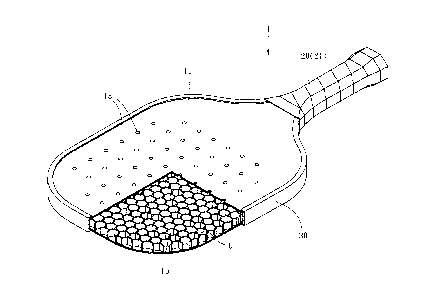
present
invention;
FIG. 2 is a partial cut-away perspective view of the pickleball paddle in
accordance
with the present invention; and
FIG. 3 is a partial longitudinal cross-sectional view of the pickleball paddle
in
accordance with the present invention.
DETAILED DESCRIPTION OF THE INVENTION
First of all, it is to be mentioned that throughout the entire specification,
including the
following embodiments and claims, the directional terms such as "up", "down",
"inside",
"outside", "top" and "bottom" are based on the direction in the drawings.
Besides, in
the following embodiments and the appendix drawings, same reference numerals
designate
same or similar elements or the structural features thereof.
Referring to FIG. 1, a pickleball paddle 1 of the present invention comprises
a ball-
hitting portion 10, a grip portion 20 connected with the ball-hitting portion
10, and an edge
3
CA 3038087 2019-03-26

band 30.
As shown in FIGS. 1 and 3, the ball-hitting portion 10 is used for hitting a
ball. The
ball-hitting portion 10 has a rectangular shape with a pair of long sides 11
and a pair of short
sides 12. The length of the short side 11 is ranged from 7 inches to 8.75
inches, and the length
of the long side 12 is ranged from 9.5 inches to 12 inches so as to meet the
size requirements
of the pickleball paddle 1. The ball-hitting portion 10 has a first surface
layer 13, a first carbon
fiber plate 14, an inner layer 15, a second carbon fiber plate 16, and a
second surface layer 17
from top to bottom. The first surface layer 13 and the second surface layer 17
are used for
touching the ball. The inner layer 15 is disposed between the first surface
layer 13 and the
second surface layer 17, and defines a honeycomb shape in cross-section (as
shown in FIG. 2).
The aforesaid honeycomb shaped structure is a single layer structure
constructed by a plurality
of units U each having a hexagonal shape. The first carbon fiber plate 14 and
the second carbon
fiber plate 16 are made of fiberglass for enhancing the hardness of the ball-
hitting portion 10.
Further, the ball-hitting portion 10 has a plurality of through holes 18 (this
embodiment has
fifty-eight through holes 18). Each of the through holes 18 passes straight
through the first
surface layer 13, the first carbon fiber plate 14, the inner layer 15, the
second carbon fiber plate
16, and the second surface layer 17 in a way that each of the through holes 18
is vertical to the
first surface layer 13, such that air flow can be guided by the through holes
18 to pass through
the ball-hitting portion 10 for reducing the wind resistance. The through
holes 18 are roughly
arranged in a square array and spaced equally from each other, wherein the
first column has
four through holes 18, and the second to sixth columns each have eight through
holes 18, and
the ninth column has six through holes 18.
The grip portion 20 is used for being gripped by a user. The length of the
grip portion
20 is ranged from 4 inches to 5.5 inches to meet the size requirements of the
pickleball paddle
1. A grip tape 21 is attached to the grip portion 20 for providing anti-slip
and shockproof effects.
4
CA 3038087 2019-03-26

The edge band 30 is made of PVC. The edge band 30 is attached to the periphery
of
the ball-hitting portion 10 for protecting the periphery of the ball-hitting
portion 10 from
damage.
It can be known from the above description that since the inner layer 15 is
constructed
of a honeycomb shaped structure, the weight of the pickleball paddle 1 of the
present invention
is reduced and the structure strength of the pickleball paddle 1 of the
present invention is
maintained, thereby allowing the pickleball paddle 1 of the present invention
to be swung easily
by the user. Further, by means of the through holes 18, when the user swings
the pickleball
paddle 1 of the present invention, the air flow can be guided easily from the
first surface layer
13 to the second surface layer 17 through the through holes 18 for effectively
reducing the wind
resistance, such that the user will spend less effort swinging the pickleball
paddle 1 of the
present invention.
It must be stated that this embodiment defines the length of the short side 11
that is
in the range from 7 inches to 8.75 inches, the length of the long side 12 that
is in the range from
9.5 inches to 12 inches, and the length of the grip portion 20 that is in the
range from 4 inches
to 5.5 inches. If a paddle has a dimension lying outside the above-described
size range, it is not
the pickleball paddle as defined in the present invention.
5
CA 3038087 2019-03-26

Representative Drawing
A single figure which represents the drawing illustrating the invention.
Administrative Status

2024-08-01:As part of the Next Generation Patents (NGP) transition, the Canadian Patents Database (CPD) now contains a more detailed Event History, which replicates the Event Log of our new back-office solution.

Please note that "Inactive:" events refers to events no longer in use in our new back-office solution.

For a clearer understanding of the status of the application/patent presented on this page, the site Disclaimer , as well as the definitions for Patent , Event History , Maintenance Fee  and Payment History  should be consulted.

Event History

Description Date
Application Not Reinstated by Deadline 2022-08-16
Inactive: Dead - No reply to s.86(2) Rules requisition 2022-08-16
Letter Sent 2022-03-28
Deemed Abandoned - Failure to Respond to an Examiner's Requisition 2021-08-16
Examiner's Report 2021-04-16
Inactive: Adhoc Request Documented 2021-03-15
Inactive: Office letter 2021-03-15
Inactive: Delete abandonment 2021-03-15
Inactive: Correspondence - Prosecution 2021-02-16
Common Representative Appointed 2020-11-07
Application Published (Open to Public Inspection) 2020-09-26
Inactive: Cover page published 2020-09-25
Deemed Abandoned - Failure to Respond to an Examiner's Requisition 2020-08-31
Inactive: COVID 19 - Deadline extended 2020-08-19
Examiner's Report 2020-04-23
Inactive: Report - No QC 2020-03-27
Common Representative Appointed 2019-10-30
Inactive: Filing certificate - RFE (bilingual) 2019-04-05
Filing Requirements Determined Compliant 2019-04-05
Inactive: IPC assigned 2019-04-03
Inactive: First IPC assigned 2019-04-03
Inactive: IPC assigned 2019-04-03
Letter Sent 2019-04-01
Application Received - Regular National 2019-03-28
Request for Examination Requirements Determined Compliant 2019-03-26
All Requirements for Examination Determined Compliant 2019-03-26

Abandonment History

Abandonment Date Reason Reinstatement Date
2021-08-16
2020-08-31

Maintenance Fee

The last payment was received on 2021-01-07

Note : If the full payment has not been received on or before the date indicated, a further fee may be required which may be one of the following

  • the reinstatement fee;
  • the late payment fee; or
  • additional fee to reverse deemed expiry.

Please refer to the CIPO Patent Fees web page to see all current fee amounts.

Fee History

Fee Type Anniversary Year Due Date Paid Date
Application fee - standard 2019-03-26
Request for examination - standard 2019-03-26
MF (application, 2nd anniv.) - standard 02 2021-03-26 2021-01-07
Owners on Record

Note: Records showing the ownership history in alphabetical order.

Current Owners on Record
YMA CORPORATION
Past Owners on Record
JING-BIN CHIANG
Past Owners that do not appear in the "Owners on Record" listing will appear in other documentation within the application.
Documents

To view selected files, please enter reCAPTCHA code :


To view images, click a link in the Document Description column. To download the documents, select one or more checkboxes in the first column and then click the "Download Selected in PDF format (Zip Archive)" or the "Download Selected as Single PDF" button.

List of published and non-published patent-specific documents on the CPD .

If you have any difficulty accessing content, you can call the Client Service Centre at 1-866-997-1936 or send them an e-mail at CIPO Client Service Centre.


Document
Description 
Date
(yyyy-mm-dd) 
Number of pages   Size of Image (KB) 
Representative drawing 2020-08-24 1 14
Description 2019-03-26 5 209
Abstract 2019-03-26 1 21
Claims 2019-03-26 2 54
Drawings 2019-03-26 3 41
Cover Page 2020-08-24 2 50
Acknowledgement of Request for Examination 2019-04-01 1 174
Filing Certificate 2019-04-05 1 223
Courtesy - Abandonment Letter (R86(2)) 2021-10-12 1 550
Commissioner's Notice - Maintenance Fee for a Patent Application Not Paid 2022-05-09 1 561
Maintenance fee payment 2021-01-07 1 26
Prosecution correspondence 2021-02-16 3 82
Courtesy - Office Letter 2021-03-15 1 157
Examiner requisition 2021-04-16 4 170