Note: Descriptions are shown in the official language in which they were submitted.
CA 03041605 2019-04-24
WO 2018/078619 PCT/IL2017/051163
APPARATUS AND METHODS FOR PREDICTING THERAPY OUTCOME
CROSS-REFERENCE TO RELATED APPLICATIONS
The present application claims priority from US Provisional Patent Application
62/412,598 to Alyagon, filed Oct. 25, 2016, entitled "Predicting therapy
outcome," which is
incorporated herein by reference.
FIELD OF EMBODIMENTS OF THE INVENTION
Some applications of the present invention relate to apparatus and methods for
use with
transcranial magnetic stimulation, and more particularly, to apparatus and
methods for
predicting the outcome of treatment of a condition using transcranial magnetic
stimulation.
BACKGROUND
Transcranial magnetic stimulation (TMS) is widely used as a research tool to
study
aspects of the human brain and has recently been used as a tool in therapeutic
neuropsychiatry. Biological tissue is stimulated using magnetic fields
produced by passing
electrical currents through electrically conductive materials positioned
adjacent to the tissue.
The magnetic fields cause electric conduction in brain cells, and, as a
consequence, generation
of action potentials.
The magnetic stimulation is delivered or generated by a coil, positioned on
the patient's
scalp, inducing nerve stimulation within the brain. Deep transcranial magnetic
stimulation is
described as being used in the treatment of depression and other
neuropsychiatric disorders
such as autism, post-traumatic stress disorder (PTSD), addictive behaviors
(including smoking,
eating disorders and drug addiction), schizophrenia, Parkinson's disease, and
others. For
example, a device for performing deep transcranial magnetic stimulation is
described in
International Publication Number WO 02/32504, which is incorporated herein by
reference.
The device described therein includes a base and an extension portion, the
base having
individual windings for individual paths of current flow, and the extension
portion designed so
as to minimize unwanted stimulation of other regions of the brain.
Reduced excitability of the right prefrontal cortex has been implicated in
attention
deficit/hyperactivity disorder (ADHD). Despite its high prevalence, available
treatments for
ADHD are not tolerable by many patients.
1
CA 03041605 2019-04-24
WO 2018/078619 PCT/IL2017/051163
SUMMARY OF EMBODIMENTS
In accordance with some applications of the present invention, one or more
pulses of
transcranial magnetic stimulation (e.g., one or more trains of transcranial
magnetic stimulation)
are applied to a subject. For example, the subject may be a subject suffering
from ADHD.
Within a given time period of applying one of the one or more pulses of the
transcranial
magnetic stimulation to the subject, an electrophysiological signal
(typically, an
electroencephalography (EEG) signal) of the subject is detected. At least
partially in response
thereto, an outcome of treating the subject for a neuropsychiatric condition,
using a given
therapy is predicted, typically by means of a computer processor.
For some applications of the present invention, an electroencephalography
(EEG)
signal of the subject is detected. The power of a given frequency band within
the detected EEG
signal is calculated. For example, the power of a low gamma frequency band
(e.g., a band
from approximately 30 Hz to approximately 40 Hz) may be calculated. For some
applications,
the low gamma frequency band is normalized by being divided by the power of a
different
frequency band, such as an alpha frequency band (e.g., a band from
approximately 8 Hz to
approximately 15 Hz). At least partially based upon the power of the given
frequency band,
the outcome of treating the subject for a neuropsychiatric condition, using a
given therapy is
predicted.
For some applications, activity-related features are identified in the EEG
signal, and a
brain network activity (B NA) pattern is constructed based on those features.
The brain network
activity pattern typically includes a plurality of nodes, each representing a
feature of the
activity-related features, and a connectivity weight assigned to each pair of
nodes.
For some applications, the pulses of transcranial magnetic stimulation are
transmitted
to the EEG system (or to a processor that receives and processes the EEG
signal), and are used
for identifying evoke responses in the brain. For some applications, the evoke
responses are
used for identifying activity-related features, and for constructing a brain
network activity
pattern.
For some applications, the nodes of the brain network activity pattern
represent clusters
of vectors of data characteristics. According to some applications of the
invention, each vector
of data characteristics of each cluster corresponds to data obtained from a
different subject.
2
CA 03041605 2019-04-24
WO 2018/078619 PCT/IL2017/051163
Alternatively, all vectors of data characteristics correspond to data obtained
from the same
subject but in response to a separate transcranial magnetic stimulation
stimulus.
According to some applications of the invention, a connectivity weight
comprises a
weight index calculated based on at least one cluster property selected from
the group
consisting of: (i) a number of vectors in a corresponding pair of clusters;
(ii) a variability among
numbers of vectors in the corresponding pair of clusters; (iii) a width of
time windows
associated with each cluster of the corresponding pair of clusters; (iv) a
latency difference
separating the corresponding pair of clusters, wherein the latency is with
respect to time at
which the transcranial magnetic stimulation pulse was applied; (v) amplitude
of a signal
associated with the corresponding pair of clusters; (vi) frequency of a signal
associated with
the corresponding pair of clusters; and (vii) the width of a spatial window
defining the clusters.
There is therefore provided, in accordance with some applications of the
present
invention, apparatus for use with electrophysiological signal detecting
electrodes, and a
transcranial magnetic stimulation device, the apparatus including:
an output device; and
a computer processor configured to:
drive the transcranial stimulation device to apply one or more pulses of
transcranial magnetic stimulation to a subject;
within a given time period of applying one of the one or more pulses of
transcranial magnetic stimulation to the subject, detect an
electrophysiological signal
of the subject, using the electrophysiological signal detecting electrodes;
at least partially in response thereto, predict an outcome of treating the
subject
for a neuropsychiatric condition, using a given therapy; and
generate an output on the output device in response to the predicted outcome.
In some applications, the computer processor is configured to predict the
outcome of
treating the subject for the neuropsychiatric condition, using the given
therapy, by predicting
an outcome of treating the subject for depression using transcranial magnetic
stimulation.
In some applications, the computer processor is configured to predict the
outcome of
treating the subject for the neuropsychiatric condition, using the given
therapy, by predicting
an outcome of treating the subject for major depressive disorder using
transcranial magnetic
stimulation.
3
CA 03041605 2019-04-24
WO 2018/078619 PCT/IL2017/051163
In some applications, the computer processor is configured to predict the
outcome of
treating the subject for the neuropsychiatric condition, using the given
therapy, by predicting
an outcome of treating the subject for ADHD using transcranial magnetic
stimulation.
In some applications, the computer processor is configured to detect the
electrophysiological signal of the subject by detecting an
electroencephalography signal of the
subject within the given time period of applying one of the one or more pulses
of transcranial
magnetic stimulation to the subject.
In some applications, the computer processor is configured to predict the
outcome of
treating the subject for the neuropsychiatric condition using the given
therapy by predicting a
response time of the subject to being treated with the given therapy.
In some applications, the computer processor is configured to predict the
outcome of
treating the subject for the neuropsychiatric condition using the given
therapy by predicting a
rate of improvement in the subject's neuropsychiatric condition, in response
to being treated
with the given therapy.
In some applications:
the computer processor is further configured to detect an
electroencephalography
(EEG) signal of the subject while the subject performs a task, and
the computer processor is configured to predict the outcome of treating the
subject for
the neuropsychiatric condition using the given therapy, based upon the
electrophysiological
signal of the subject and a component of the EEG signal of the subject that
was detected while
the subject performed the task.
In some applications, the computer processor is configured to drive the
transcranial
stimulation device to apply the one or more pulses of transcranial magnetic
stimulation to the
subject by driving the transcranial stimulation device to apply one or more
trains of transcranial
magnetic stimulation to the subject.
In some applications, the computer processor is configured to detect the
electrophysiological signal of the subject by detecting the
electrophysiological signal of the
subject, while one of the one or more trains of transcranial magnetic
stimulation is being
applied to the subject.
4
CA 03041605 2019-04-24
WO 2018/078619 PCT/IL2017/051163
In some applications, the computer processor is configured to detect the
electrophysiological signal of the subject by detecting the
electrophysiological signal of the
subject, between trains of transcranial magnetic stimulation being applied to
the subject.
In some applications, the computer processor is further configured to
construct a brain
network activity pattern based on the electrophysiological signal, and the
computer processor
is configured to predict the outcome of treating the subject for the
neuropsychiatric condition
using the given therapy based on the brain network activity pattern.
In some applications, the computer processor is further configured to
calculate a brain
network activity pattern similarity score, by comparing the brain network
activity pattern to a
group brain network activity pattern that is based upon electrophysiological
signals acquired
from a group of subjects, and the computer processor is configured to predict
the outcome of
treating the subject for the neuropsychiatric condition using the given
therapy based on the
brain network activity pattern similarity score.
In some applications, the computer processor is configured to construct the
brain
network activity pattern by constructing a brain network activity pattern that
includes:
a plurality of nodes, each representing a comparison of features and relations
among
features in the electrophysiological signal to features and relations among
features of reference
neurophysiological data; and
connectivity weights assigned to respective pairs of nodes.
In some applications, the computer processor is configured to construct the
brain
network activity pattern by constructing a brain network activity pattern
using
electrophysiological signals acquired from a group of subjects as the
reference
neurophysiological data.
In some applications, the computer processor is configured to construct the
brain
network activity pattern by constructing a brain network activity pattern
using, as the reference
neurophysiological data, electrophysiological signals acquired from a group of
subjects, each
applied with an initial pulse of transcranial magnetic stimulation.
In some applications, the computer processor is configured to construct the
brain
network activity pattern by constructing a brain network activity pattern in
which each node
represents a cluster of vectors of data characteristics, and the connectivity
weights of each one
5
CA 03041605 2019-04-24
WO 2018/078619 PCT/IL2017/051163
of the respective nodes represents at least one cluster property describing a
pair of clusters
represented by said the respective pair of nodes.
In some applications, the computer processor is configured to construct the
brain
network activity pattern by constructing a brain network activity pattern in
which the at least
one cluster property includes a latency difference separating the pair of
clusters.
In some applications, the computer processor is further configured to
calculate a power
of a given frequency band within the detected electrophysiological signal, and
the computer
processor is configured to predict the outcome of treating the subject for the
neuropsychiatric
condition using the given therapy at least partially in response to the power
of the given
frequency band.
In some applications:
the computer processor is further configured to calculate powers of one or
more
additional frequency bands within the detected electrophysiological signal,
and
the computer processor is configured to predict the outcome of treating the
subject for
the neuropsychiatric condition using the given therapy, based upon a
combination of the power
of the given frequency band and the powers of the one or more additional
frequency bands.
In some applications, the computer processor is configured to predict the
outcome of
treating the subject for the neuropsychiatric condition using the given
therapy, based upon a
ratio of the power of the given frequency band and the power of one of the one
or more
additional frequency bands.
In some applications, the computer processor is configured to detect the
electrophysiological signal of the subject by detecting an
electroencephalography signal of the
subject within the given time period of applying one of the one or more pulses
of transcranial
magnetic stimulation to the subject.
In some applications, the computer processor is configured to calculate the
power of
the given frequency band within the detected electrophysiological signal by
calculating a
power of a low gamma band within the detected electroencephalography signal.
In some applications:
the computer processor is further configured to calculate a power of an alpha
band
within the detected electroencephalography signal, and
6
CA 03041605 2019-04-24
WO 2018/078619 PCT/IL2017/051163
the computer processor is configured to predict the outcome of treating the
subject for
the neuropsychiatric condition using the given therapy, based upon a
combination of the power
of the low gamma band within the detected electroencephalography signal and
the power of
the alpha band within the detected electroencephalography signal.
In some applications, the computer processor is configured to predict the
outcome of
treating the subject for the neuropsychiatric condition using the given
therapy, based upon a
ratio of the power of the low gamma band within the detected
electroencephalography signal
and the power of the alpha band within the detected electroencephalography
signal.
There is further provided, in accordance with some applications of the present
invention, a computer software product, for use with an output device,
electrophysiological
signal detecting electrodes, and a transcranial magnetic stimulation device,
the computer
software product including a non-transitory computer-readable medium in which
program
instructions are stored, which instructions, when read by a computer cause the
computer to
perform the steps of:
driving the transcranial stimulation device to apply one or more pulses of
transcranial
magnetic stimulation to a subject;
within a given time period of applying one of the one or more pulses of
transcranial
magnetic stimulation to the subject, detecting an electrophysiological signal
of the subject,
using the electrophysiological signal detecting electrodes;
at least partially in response thereto, predicting an outcome of treating the
subject for a
neuropsychiatric condition, using a given therapy; and
generating an output on the output device in response to the predicted
outcome.
There is further provided, in accordance with some applications of the present
invention, a method including:
applying one or more pulses of transcranial magnetic stimulation to a subject;
within a given time period of applying one of the one or more pulses of
transcranial
magnetic stimulation to the subject, detecting an electrophysiological signal
of the subject;
at least partially in response to the detected electrophysiological signal,
predicting an
outcome of treating the subject for a neuropsychiatric condition, using a
given therapy.
The present invention will be more fully understood from the following
detailed
description of embodiments thereof, taken together with the drawings, in
which:
7
CA 03041605 2019-04-24
WO 2018/078619 PCT/IL2017/051163
BRIEF DESCRIPTION OF THE DRAWINGS
Fig. 1 is a schematic illustration of a transcranial magnetic stimulation
(TMS) device
applying TMS to a subject, while an electrophysiological signal of the
subject, such as an
electroencephalography (EEG) signal of the subject, is detected using
electrodes, in accordance
with some applications of the present invention;
Fig. 2 is a bar chart indicating the responses of ADHD patients to stimulation
of the
right prefrontal cortex using respective types of transcranial magnetic
stimulation coils, which
is performed in accordance with some applications of the present invention;
Figs. 3A, 3B, and 3C are graphs showing the correlation between T-scores of
ADHD
patients and of healthy subjects to respective indicators, which are
calculated in accordance
with some applications of the present invention;
Fig. 4 shows an intra-treatment EEG recording of a subject, from which a two-
second-
segment is sampled, in accordance with some applications of the present
invention;
Fig. 5 is a graph indicating, for ADHD patients to whom deep transcranial
magnetic
stimulation was applied, the degree of correlation between (a) improvements to
patients' T-
scores, and (b) the power of respective frequency components of two-second
interval EEG
samples as recorded at an initial treatment session, in accordance with some
applications of the
present invention;
Figs. 6A, 6B, and 6C are graphs showing the relationship between improvements
to T-
scores of ADHD patients, and the power of the alpha frequency band of an intra-
treatment EEG
that was recorded on the first day of a treatment, for patients that were
treated using,
respectively, a sham coil (Fig. 6A), a figure-eight coil (Fig. 6B), and a dTMS
coil (Fig. 6C);
Figs. 7A, 7B, and 7C are graphs showing the relationship between improvements
to T-
scores of ADHD patients, and the power of the beta frequency band of an intra-
treatment EEG
that was recorded on the first day of a treatment, for patients that were
treated using,
respectively, a sham coil (Fig. 7A), a figure-eight coil (Fig. 7B), and a dTMS
coil (Fig. 7C);
Figs. 8A, 8B, and 8C are graphs showing the relationship between improvements
to T-
scores of ADHD patients, and the power of the low gamma frequency band of an
intra-
treatment EEG that was recorded on the first day of a treatment, for patients
that were treated
8
CA 03041605 2019-04-24
WO 2018/078619 PCT/IL2017/051163
using, respectively, a sham coil (Fig. 8A), a figure-eight coil (Fig. 8B), and
a dTMS coil (Fig.
8C);
Figs. 9A, 9B, and 9C are graphs showing the relationship between improvements
to T-
scores of ADHD patients, and a ratio of the power of the low gamma frequency
band of an
intra-treatment EEG that was recorded on the first day of a treatment to the
power of the alpha
frequency band of the EEG recording, for patients that were treated using,
respectively, a sham
coil (Fig. 9A), a figure-eight coil (Fig. 9B), and a dTMS coil (Fig. 9C);
FIG. 10A is a schematic illustration showing a representative example of a
brain
network activity (BNA) pattern which can be extracted from EEG data, in
accordance with
some applications of the present invention;
Fig. 10B shows a representation of times at which respective unitary events
within the
EEG signals of respective subjects took place, in accordance with some
applications of the
present invention; and
Figs 10C, 10D, and 10E shows respective examples of pairs of nodes and
corresponding
edges of a brain network activity pattern, in accordance with some
applications of the present
invention;
Fig. 11A is a graph indicating, for major depressive disorder patients to whom
dTMS
was applied, the degree of correlation between (a) improvements to patients'
Hamilton
depression rating scale ("HDRS") of major depressive disorder patients after
four weeks of
dTMS treatment versus (b) Long Interval Cortical Inhibition TMS -evoked
potentials (LICI-
TEP) deflection values corresponding to the difference between the single
pulse and the second
pulse in a pair that was recorded on the first day of a treatment prior to
initiation of treatment,
in accordance with some applications of the present invention;
Fig. 11B is a graph indicating, for major depressive disorder patients to whom
dTMS
was applied, the degree of correlation between (a) improvements to patients'
HDRS after four
weeks of dTMS treatment versus (b) LICI-TEP deflection values generated by a
single pulse
that was recorded on the first day of a treatment prior to initiation of
treatment, in accordance
with some applications of the present invention;
Figs. 12A and 12B are graphs indicating, for major depressive disorder
patients to
whom dTMS was applied, the degree of correlation between (a) improvements to
patients'
HDRS measure after four weeks of TMS treatment, versus (b) the power of
respective
9
CA 03041605 2019-04-24
WO 2018/078619 PCT/IL2017/051163
frequency components of thirteen-second interval EEG samples as recorded at
the indicated
EEG electrode at the first treatment session prior to initiation of treatment,
FIG. 12A
corresponding to a high-frequency wave (20-40 Hz) at electrode location F7,
and FIG. 12B
corresponding to a Low Gamma wave (30-40 Hz) at electrode location F7, in
accordance with
some applications of the present invention;
Fig. 13A is a graph showing the relationship between (a) the percentage
improvement
to major depressive disorder patients' HDRS after three weeks of treatment
versus (b) the
patients' brain network activity similarity scores generated by single pulse
TEP as recorded
prior to treatment commencing and as compared to the brain network activity of
healthy
subjects, in accordance with some applications of the present invention;
Fig. 13B is a graph showing the relationship between (a) similarity scores of
the brain
network activity of major depressive disorder patients generated by single
pulse TEP, as
compared to the brain network activity of major depressive disorder patients,
and (b) the
patients' HDRS, in accordance with some applications of the present invention;
Figs. 14A and 14B are graphs showing the relationship between (a) the time
after
initiating dTMS treatment of major depressive disorder patients to respective
percentage
improvements from pre-treatment baseline in the patients' HDRS, and (b) the
power of
respective frequency components of the thirteen-second interval EEG samples as
recorded at
respective EEG electrodes prior to treatment commencing, in accordance with
some
applications of the present invention; and
Figs 15A, 15B, and 15C are flowcharts showing steps that are performed by a
computer
processor, in accordance with some applications of the present invention.
DETAILED DESCRIPTION OF EMBODIMENTS
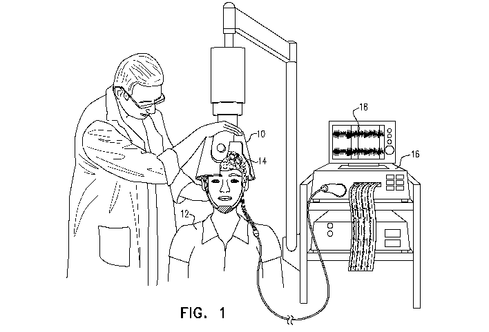
Reference is now made to Fig. 1, which is a schematic illustration of a
transcranial
magnetic stimulation (TMS) device 10 applying TMS to a subject 12, while an
electrophysiological signal of the subject, e.g., an electroencephalography
(EEG) signal of the
subject, is detected using electrodes 14, in accordance with some applications
of the present
invention. Typically, the TMS device and the electrodes are operatively
coupled to one or
more computer processors 16. Further typically, a user inputs data into the
computer processor,
and/or receives data from computer processor via one or more user interface
devices. For
CA 03041605 2019-04-24
WO 2018/078619 PCT/IL2017/051163
example, as shown in Fig. 1, the computer processor may generate an output to
the user via an
output device, such as monitor 18.
In accordance with some applications of the present invention, one or more
pulses of
transcranial magnetic stimulation (e.g., a train of pulses that includes a
plurality of pulses) are
applied to a subject. For example, the subject may be a subject suffering from
attention deficit
hyperactivity disorder (ADHD). Within a given time period of having applied
one of the one
or more pulses of transcranial magnetic stimulation to the subject, an
electrophysiological
signal (typically, an electroencephalography (EEG) signal) of the subject is
detected. At least
partially in response thereto, an outcome of treating the subject for a
neuropsychiatric
condition, using a given therapy is predicted.
The transcranial magnetic stimulation (TMS) pulses may be applied according to
any
protocol known in the art, including, without limitation, one or more of the
protocols known
as repetitive TMS, Long Interval Cortical Inhibition (LICI), Short Interval
Cortical Inhibition
(SICI), contralateral Cortical Silent Period (CSP), paired pulse TMS, and
repetitive paired-
pulse TMS. Any commercially available TMS device known in the art may be
utilized.
For some applications of the present invention, the subject's EEG signal is
detected.
The power of a given frequency band within the detected EEG signal is
calculated. For
example, a low gamma frequency band (e.g., a band from approximately 30 Hz
(e.g., 30 Hz
plus/minus 5 Hz) to approximately 40 Hz (e.g., 40 Hz plus/minus 5 Hz)) may be
calculated.
For some applications, the low gamma frequency band is normalized by being
divided by the
power of a different frequency band, such as an alpha frequency band (e.g., a
band from
approximately 8 Hz (e.g., 8 Hz plus/minus 2 Hz) to approximately 15 Hz (e.g.
15 Hz
plus/minus 3 Hz)). At least partially in response to the power of the given
frequency band, the
outcome of treating the subject for a neuropsychiatric condition, using a
given therapy is
predicted.
The pulses of TMS can be transmitted to the EEG system (or to a computer
processor
that receives and processes the EEG signal, e.g., computer processor 16). For
some such
applications, the EEG signal is analyzed to extract event-related measures,
such as event related
potentials (ERPs) or event related fields (ERFs). These measures can define
evoked responses
in the brain, and the evoked responses can be used for identifying activity-
related features and
for constructing a brain network activity pattern. For some applications, time
stamps in the
11
CA 03041605 2019-04-24
WO 2018/078619 PCT/IL2017/051163
EEG signal are synchronized with the stimulus provided by the TMS pulses to
establish a
timeline of the response and extract data features responsively to this
timeline. Typically, but
not necessarily, the collection of the EEG signal is ongoing, such that the
signal is collected
continuously, before, during and/or after the TMS stimulus.
For some applications, the EEG signal is analyzed immediately after
acquisition
("online analysis"), and/or it is recorded and stored, and, thereafter,
analyzed ("offline
analysis").
Reference is now made to Fig. 2, which is a bar chart indicating the responses
of ADHD
patients to stimulation of the right prefrontal cortex using, respectively,
(a) a deep transcranial
magnetic stimulation (dTMS) coil, (b) a figure-eight transcranial magnetic
stimulation (TMS)
coil, and (c) a sham TMS coil. The ADHD patients were identified as suffering
from ADHD
using standard tests, such as Conners' Adult ADHD Rating Scales.
The left-most bar of the bar chart of Fig. 2 shows the results of treating a
group of 15
ADHD patients using a dTMS coil. The patients were stimulated using a coil
configured to
apply dTMS, for example, as described in US 7,407,478 to Zangen, US 8,608,634
to Zangen,
and/or US 2014/0235928 to Zangen, all of which references are incorporated
herein by
reference. 15 daily treatment sessions were applied to each of the patients
over a period of
three weeks, the treatment being applied over five daily sessions each week.
In each of the
daily treatments that were applied to each of the patients, 40 stimulation
trains were applied to
the right prefrontal cortex. Each of the trains had a duration of 2 seconds,
and there was a 20
second inter-train interval, between each of the trains. The stimulation was
applied at a
frequency of 18 Hz.
As shown, on average the dTMS stimulation resulted in an improvement of 8 to
the T-
score of the patients, the T-scores being measured in accordance with Conners'
Adult ADHD
Rating Scales. The above results had a p-value of less than 0.05.
The middle bar of the bar chart of Fig. 2 shows the results of treating a
group of 11
ADHD patients using a figure-eight stimulation coil. The patients were treated
using a
generally similar treatment protocol to the above-described protocol. As
shown, the
stimulation using the figure-eight coil resulted in a lower average
improvement to the patients'
T-scores than that measured on the patients who were stimulated using a dTMS
coil.
12
CA 03041605 2019-04-24
WO 2018/078619 PCT/IL2017/051163
The right-most bar of the bar chart of Fig. 2 shows the results of treating a
group of 12
ADHD patients using a sham TMS coil. The patients were treated using a
generally similar
treatment protocol to the above-described protocol. As shown, the stimulation
using the sham
coil resulted in a lower average improvement to the patients' T-scores than
that measured on
the patients who were stimulated using a dTMS coil.
The results shown in Fig. 2 indicate that applying dTMS to the pre-frontal
cortex may
be a suitable treatment for at least some ADHD patients.
In conjunction with the above-described treatments, EEG recordings were taken
from
the patients, before, during and after the first and the last days of
treatment. In addition, EEG
recordings were taken (a) during a stop signal task (SST), and (b) following a
single TMS pulse
applied to the right pre-frontal cortex, using a figure-eight coil.
Reference is now made to Figs. 3A-C, which are graphs showing the correlation
between T-scores of ADHD patients and of healthy subjects and respective
indicators, in
accordance with some applications of the present invention.
At baseline (i.e., before repetitive TMS was applied), event-related
potentials of the
ADHD patients were recorded during stop signal tasks. As a control, event-
related potentials
of healthy subjects were also recorded during similar stop signal tasks. It
was found that both
for successful stops and unsuccessful stops, there was a difference between
the amplitudes of
components of the event-related potentials of the ADHD patients compared to
those of the
healthy subjects. For example, substantially lower amplitudes of the N200 and
P300
components recorded during the stop signal tasks, were evident in the ADHD
patients
compared to the healthy subjects.
Reference is now made to Fig. 3A, which is a graph indicating the relationship
between
the T-scores of both the ADHD patients and the healthy subjects and the P300
amplitude
recorded during unsuccessful stop signal tasks performed by the
patients/subjects. The P300
amplitude was recorded using frontal central and parietal electrodes. As
shown, there is a
correlation between the T-scores and the P300 amplitudes, the correlation
coefficient being -
0.51.
In addition to the above, a single pulse of TMS was applied to the right
prefrontal cortex
of the ADHD patients and the healthy subjects using a figure-eight coil,
following which the
13
CA 03041605 2019-04-24
WO 2018/078619 PCT/IL2017/051163
patients'/subjects' EEG signals were recorded. It was found that the TMS -
evoked potential of
the ADHD patients was lower than that of the healthy subjects.
Reference is now made to Fig. 3B, which is a graph indicating the relationship
between
the T-scores of both the ADHD patients and the healthy subjects and the TMS -
evoked
potentials ("TEP"). As shown, there is a correlation between the T-scores and
the TMS-evoked
potentials, the correlation coefficient being - 0.39. (It is noted that in
Fig. 3B, the correlation
between the T-scores of both the ADHD patients and the healthy subjects and
the TMS -evoked
potentials appears to be positive, but this is because the TMS-evoked
potentials were negative,
and a logarithmic scale was used to measure the TMS-evoked potentials.)
Reference is now made to Fig. 3C, which is a graph indicating the correlation
between
the T-scores of both the ADHD patients and the healthy subjects and a
predicted ADHD
symptoms score, the predicted score being based upon (a) the P300 amplitudes
recorded during
unsuccessful stop signal tasks performed by the patients/subjects (indicated
in Fig. 3A), and
(b) the TMS-evoked potentials of the patients/subjects (indicated in Fig. 3B),
in a multiple
regression model. As shown, there is substantial correlation between the T-
scores and the
ADHD-indicator, the correlation coefficient being 0.61.
In view of the results shown in Figs. 3A-C, for some applications of the
present
invention, TMS is applied to a subject who is suspected of suffering from
ADHD. Typically,
the TMS is applied at least to the subject's right pre-frontal cortex. The
subject's EEG is
detected at a given time interval following the TMS stimulation. At least
partially in response
to a characteristic of the TMS -evoked EEG signal, it is determined whether or
not the subject
suffers from ADHD, and/or an ADHD score of the subject is calculated. For some
applications,
in addition to the TMS-evoked potential, event-related potentials are measured
during stop
signal tasks that are performed by the subject. At least partially in response
to (a) a
characteristic of the TMS-evoked EEG signal, and (b) a component of the event-
related
potentials measured during the stop signal tasks, it is determined whether or
not the subject
suffers from ADHD, and/or an ADHD score of the subject is calculated.
Reference is now made to Fig. 4, which shows an intra-treatment EEG recording
of a
subject, in accordance with some applications of the present invention. The
recording is from
a subject who has ADHD and was recorded while the subject was receiving dTMS
in
accordance with the stimulation protocol described hereinabove, with reference
to Fig. 2. As
14
CA 03041605 2019-04-24
WO 2018/078619 PCT/IL2017/051163
described hereinabove, in each of the daily treatments, 40 stimulation trains
were applied to
the subject's right prefrontal cortex. Each of the trains had a duration of 2
seconds, and there
was a 20 second inter-train interval, between each of the trains. During the
aforementioned
treatment, EEG measurements were recorded from the subject.
The EEG recordings from inter-train intervals were sampled over two-second
segments. The two-second segments were sampled after at least one second had
passed from
the end of the previous TMS train, in order to reduce the effects of direct
artifacts of the dTMS
stimulation on the EEG signal. Fig. 4 shows an example of such a sampling, a
two second
segment being shown to be sampled approximately one second after the end of
the previous
TMS train. (Although the two-second interval shown in Fig. 4 is shown as
commencing 1
second after the end of the previous dTMS train, the characteristics of the
EEG sample that are
described hereinbelow, were also exhibited by samples that were sampled within
inter-train
intervals, but after a greater time had elapsed since the end of the previous
dTMS train.)
As described hereinabove with reference to Fig. 2, TMS (using a dTMS coil, a
figure-
eight coil, or a sham coil) was applied to ADHD patients for 15 days. The
patients' intra-
treatment EEG signals were recorded on the first, eighth and fifteenth days of
the days on
which the TMS was applied. Two-second interval sections of the inter-treatment
EEG signals
were sampled, as shown in Fig. 4, and the samples were spectrally analyzed,
such that the
powers of respective frequency components within the samples were calculated.
At the end of
the treatments, the patients' T-scores were measured in order to measure the
responsiveness of
the patients to the TMS treatments. The responsiveness of the patients to the
treatment was
then compared to the power of the respective frequency components of the two-
second interval
EEG samples as recorded at the first treatment session (i.e., as recorded
during the TMS that
was applied on the first day of the treatment).
Reference is now made to Fig. 5, which is a graph indicating, for the ADHD
patients
to whom dTMS was applied, the degree of correlation between (a) improvements
to patients'
T-scores, and (b) the power of respective frequency components of the two-
second interval
EEG samples as recorded at the FC4 EEG electrode at the first treatment
session. As shown,
there is a correlation between many frequency components of the two-second
interval EEG
samples as recorded at the first treatment session and the improvements to the
patients' T-
scores. It is noted that although the EEG signals from which the samples were
taken and
spectrally analyzed were recorded at the first treatment session of a three-
week course of
CA 03041605 2019-04-24
WO 2018/078619 PCT/IL2017/051163
treatment, the graph shown in Fig. 5 indicates that there is a correlation
between the power of
certain frequency components of the sample and the responsiveness of the
patients to the
treatment, as measured after the three-week course of treatment.
The graph shown in Fig. 5 indicates that an electrophysiological signal of a
subject
recorded within a given time period after applying TMS to the subject may
serve as an indicator
of the responsiveness of the subject to treating the subject for a given
neuropsychiatric
condition using a given therapy. Therefore, for some applications of the
present invention
computer processor 16 (Fig. 1) drives transcranial magnetic stimulation device
10 to apply one
or more pulses (e.g., one or more trains) of transcranial magnetic stimulation
to a subject.
Within a given time period of applying one of the pulses of transcranial
magnetic stimulation
to the subject, the computer processor detects an electrophysiological signal
of the subject,
using the electrophysiological signal detecting electrodes 14. At least
partially in response
thereto, the computer processor predicts an outcome of treating the subject
for a
neuropsychiatric condition, using a given therapy. For some applications, the
computer
processor generates an output on an output device (such as monitor 18) in
response to the
predicted outcome. For example, the EEG signal of a patient suffering from
ADHD may be
recorded a given time period after applying a TMS or dTMS train to the
subject, or during the
application of a TMS or dTMS train to the subject. In response thereto, the
responsiveness of
the patient to using TMS or dTMS to treat the patient for ADHD is predicted.
In EEG spectral analysis, the frequency range of approximately 8 Hz (e.g., 8
Hz
plus/minus 2 Hz) to approximately 15 Hz (e.g., 15 Hz plus/minus 3 Hz) is
described as the
alpha band, the range of approximately 15 Hz (e.g., 15 Hz plus/minus 3 Hz) to
approximately
Hz (e.g., 30 Hz plus/minus 5 Hz) is described as the beta band, and the
frequency range of
approximately 30 Hz (e.g., 30 Hz plus/minus 5 Hz) to approximately 100 Hz
(e.g., 100 Hz
25
plus/minus 10 Hz) is described as the gamma band. These categorizations are
indicated upon
the graph shown in Fig. 5. Within the context of the present application, the
frequency range
of approximately 30 Hz (e.g., 30 Hz plus/minus 5 Hz) to approximately 40 Hz
(e.g., 40 Hz
plus/minus 5 Hz) is further categorized as the low-gamma band.
Reference is now made to Figs. 6A-C, which are graphs showing the relationship
30
between improvements to T-scores of ADHD patients, and the power of the alpha
frequency
band of an intra-treatment EEG that was recorded at the FC4 EEG electrode on
the first day of
16
CA 03041605 2019-04-24
WO 2018/078619 PCT/IL2017/051163
a treatment, sampled as described hereinabove, for patients that were treated
using,
respectively, a sham coil (Fig. 6A), a figure-eight coil (Fig. 6B), and a dTMS
coil (Fig. 6C).
Reference is also made to Figs. 7A-C, which are graphs showing the
relationship
between improvements to T-scores of ADHD patients, and the power of the beta
frequency
band of an intra-treatment EEG that was recorded at the FC4 EEG electrode on
the first day of
a treatment, sampled as described hereinabove, for patients that were treated
using,
respectively, a sham coil (Fig. 7A), a figure-eight coil (Fig. 7B), and a dTMS
coil (Fig. 7C).
Reference is additionally made to Figs. 8A-C, which are graphs showing the
relationship between improvements to T-scores of ADHD patients, and the power
of the low
gamma frequency band of an intra-treatment EEG that was recorded at the FC4
EEG electrode
on the first day of a treatment, sampled as described hereinabove, for
patients that were treated
using, respectively, a sham coil (Fig. 8A), a figure-eight coil (Fig. 8B), and
a dTMS coil (Fig.
8C).
Reference is further made to Figs. 9A-C, which are graphs showing the
relationship
between (a) improvements to T- scores of ADHD patients, and (b) the power of
the low gamma
frequency band of an intra-treatment EEG that was recorded at the FC4 EEG
electrode on the
first day of a treatment, sampled as described hereinabove, and normalized by
the power of the
alpha frequency band using a decibel scale, for patients that were treated
using, respectively, a
sham coil (Fig. 9A), a figure-eight coil (Fig. 9B), and a dTMS coil (Fig. 9C).
It may be observed that, when the patients are treated using a dTMS coil
(corresponding
to the graphs shown in Figs. 6C, 7C, and 8C), then at each of the frequency
bands, there is a
degree of correlation between the power of the frequency band on the first day
of treatment
and the improvement to the patients' T-scores resulting from the treatment. By
contrast, when
the patients are treated using a sham TMS coil or a figure-eight TMS coil
(corresponding to
the graphs shown in Figs. 7A-B, 7A-B, and 8A-B), then at each of the frequency
bands, there
is no substantial correlation between the power of the frequency band on the
first day of
treatment and the improvement to the patients' T-scores resulting from the
treatment.
Furthermore, by comparing Fig. 9C to Figs. 6C, 7C, and 8C, it may be observed
that
when stimulated using a dTMS coil, the correlation to the improvements to the
T-scores
exhibited by (a) the power of the low gamma band normalized by the power of
the low alpha
17
CA 03041605 2019-04-24
WO 2018/078619 PCT/IL2017/051163
band is relatively strong compared to that of (b) the alpha band (Fig. 6C),
the beta band (Fig.
7C) and the low gamma band (Fig. 8C).
It was observed during the above-described experiments that, in general,
stimulation
using a dTMS coil caused EEG recordings subsequent to the stimulation to have
a high ratio
of low gamma power to alpha power (e.g., up to 4 dB) in the prefrontal cortex
region, when
normalized by subtracting the effects of a sham coil. Stimulation using a
figure-eight coil also
caused there to be a high ratio of low gamma power to alpha power in certain
regions of the
brain, but the effect was less than that exhibited by patients stimulated with
dTMS coils.
Based upon the above described experimental results, for some applications of
the
present invention, computer processor 16 detects an EEG signal of the subject,
using EEG
electrodes. The computer processor calculates the power of a given frequency
band within the
detected EEG signal. At least partially in response to the power of the given
frequency band,
the computer processor predicts an outcome of treating the subject for a
neuropsychiatric
condition, using a given therapy. For some applications, the computer
processor generates an
output on an output device (such as monitor 18) in response to the predicted
outcome. For
example, the EEG signal of a patient suffering from ADHD may be recorded
(e.g., after
applying dTMS to the subject). The power of a given frequency band (e.g., the
alpha band, or
the low gamma band) is calculated, and in response thereto, the responsiveness
of the patient
to using dTMS to treat the patient for ADHD is predicted. For some
applications, the powers
of two or more frequency bands are combined and/or manipulated using a
mathematical
operation. For some applications, the power of the given frequency band is
normalized by
dividing the power of the given frequency band by that of a different
frequency band. For
example, the low gamma frequency band may be normalized by being divided by
the power of
a different frequency band, such as an alpha frequency band. Alternatively or
additionally, the
powers of two or more frequency bands may be combined and/or manipulated using
a different
mathematical operation.
It is noted that the results described with reference to Figs. 6A-C, 7A-C, 8A-
C, and 9A-
C indicate that the responsiveness of an ADHD patient to treatment using dTMS
may be
predicted based upon recordings from the FC4 electrode of an EEG recording on
the first day
of treatment. However, during the course of the above-described experiments it
was observed
that at locations of EEG electrodes other than the FC4 electrode location
there also appeared
to be correlations between the responsiveness of patients to treatment and the
power of
18
CA 03041605 2019-04-24
WO 2018/078619 PCT/IL2017/051163
frequency bands of the EEG signal on the first day of treatment. In addition,
this effect was
observed during treatment with a figure-eight coil and not just using a dTMS
coil. Therefore,
the scope of the present invention includes using the apparatus and techniques
described herein
using any type of transcranial magnetic stimulation parameters, and any type
of
electrophysiological sensing, including EEG sensing, at any position, mutatis
mutandis.
For some application of the present invention, computer processor 16 detects
an
electrophysiological signal (typically, an electroencephalography (EEG)
signal) of the subject,
using electrodes 14. For some applications, activity-related features are
identified in the EEG
signal, and a brain network activity (BNA) pattern is constructed based on
those features. At
least partially in response to the brain network activity, the computer
processor predicts an
outcome of treating the subject for a neuropsychiatric condition, using a
given therapy. For
some applications, the computer processor generates an output on an output
device (such as a
display) in response to the predicted outcome.
The concept of brain network activity pattern can be better understood with
reference
to Fig. 10A which is a representative example of a brain network activity
pattern 20 which may
be extracted from the TMS-evoked EEG signal, according to some applications of
the present
invention. Brain network activity pattern 20 has a plurality of nodes 22, each
representing an
activity-related feature. For example, a node can represent a particular
frequency band
(optionally two or more particular frequency bands) at a particular location
and within a
particular time-window or latency range, optionally with a particular range of
amplitudes.
Some of nodes 22 are connected by edges 24 each representing the causal
relationship
between the nodes at the ends of the respective edge. Thus, the brain network
activity pattern
is a represented as a graph having nodes and edges. In some applications of
the invention the
brain network activity pattern includes a plurality of discrete nodes, wherein
information
pertaining to features of the data is represented only by the nodes and
information pertaining
to relationships between the features is represented only by the edges.
Fig. 10A illustrates brain network activity pattern 20 within a template 26 of
a scalp,
demonstrating the relationship between the locations of the nodes and lobes of
the brain (frontal
28, central 30, parietal 32, occipital 34 and temporal 36). The nodes in the
brain network
activity pattern can be labeled by their various characteristics. A color
coding or shape coding
visualization technique can also be employed, if desired. For example, nodes
corresponding
19
CA 03041605 2019-04-24
WO 2018/078619 PCT/IL2017/051163
to a particular frequency band can be displayed using one color or shape and
nodes
corresponding to another frequency band can be displayed using another color
or shape. For
example, red nodes may be used to correspond to Delta waves and green nodes to
correspond
to Theta waves. As shown in Fig. 10A, "red" nodes are illustrated with solid
black circles, and
"green" nodes are illustrated with a solid black circle surrounded by an outer
circle (of which
there are three in Fig. 10A).
Brain network activity pattern 20 can describe brain activity of a single
subject or a
group or sub-group of subjects. A brain network activity pattern that
describes the brain
activity of a single subject is referred to herein as a subject-specific brain
network activity
pattern, and a brain network activity pattern that describes the brain
activity of a group or sub-
group of subjects is referred to herein as a group brain network activity
pattern.
When brain network activity pattern 20 is a subject-specific brain network
activity
pattern, only vectors extracted from data of a given subject are used to
construct the brain
network activity pattern for that subject. Thus, each node corresponds to a
point in the
multidimensional space and therefore represents an activity event in the
brain. When brain
network activity pattern 20 is a group brain network activity pattern, some
nodes can
correspond to a cluster of points in the multidimensional space, and the
pattern therefore
represents an activity event which is prevalent in the group or sub-group of
subjects. Due to
the statistical nature of a group brain network activity pattern, the number
of nodes (referred
to herein as the "order") and/or edges (referred to herein as the "size") in a
group brain network
activity pattern is typically, but not necessarily, larger than the order
and/or size of a subject-
specific brain network activity pattern.
As an example for constructing a group brain network activity pattern, the
simplified
scenario illustrated in Fig. 10B is considered, wherein a "segment"
corresponds to a different
subject in a group or sub-group of subjects. The EEG signals of the group
include, in the
present example, two unitary events associated with locations A and B. Each of
these events
forms a cluster in the multidimensional space. In some applications of the
invention, each of
the clusters, referred to herein as clusters A and B, is represented by a node
in the group brain
network activity pattern. The two clusters A and B are identified as activity-
related features
since there are some individual points within these clusters that pass the
criteria for such a
relationship (the pairs of Subject Nos. 4 and 5, in the present example, as
will be explained in
further detail below). Thus, for some applications of the invention, the nodes
corresponding
CA 03041605 2019-04-24
WO 2018/078619 PCT/IL2017/051163
to clusters A and B are connected by an edge. A simplified illustration of the
resulting group
brain network activity pattern is illustrated in Fig. 10C.
A subject-specific brain network activity pattern is typically constructed by
comparing
the features and relations among features of the EEG signal collected from the
subject to the
features and relations among features of reference data, which, for some
applications,
correspond to EEG signals of the group. For such applications, points and
relationships among
points associated with the subject's signal are compared to clusters and
relationships among
clusters associated with the group's data. Consider, for example, the
simplified scenario
illustrated in Fig. 10B, wherein a "segment" corresponds to a different
subject in a group or
sub-group of subjects. Cluster A does not include a contribution from Subject
No. 3, and
cluster B does not include a contribution from Subject No. 6, since for these
subjects the
respective points fail to pass the time-window criterion. Thus, for some
applications, when a
subject-specific brain network activity pattern is constructed for Subject No.
3 it does not
include a node corresponding to location A, and when a subject-specific brain
network activity
pattern is constructed for Subject No. 6 it does not include a node
corresponding to location B.
On the other hand, both locations A and B are represented as nodes in the
subject-specific brain
network activity patterns constructed for any of Subject Nos. 1, 2, 4 and 5.
For those subjects
for which the respective points are accepted as a pair of activity-related
features (e.g., due to
the events taking place within a given time interval from one another,
corresponding to Subject
Nos. 4 and 5, in the present example), the corresponding nodes are connected
by an edge. A
simplified illustration of a subject-specific brain network activity pattern
for such a case is
shown in Fig. 10D.
Note that for this simplified example of only two nodes, the subject-specific
brain
network activity pattern of Fig. 10D is similar to the group brain network
activity pattern of
Fig. 10C. For a larger number of nodes, the order and/or size of the group
brain network
activity pattern is, as stated, typically larger than the order and/or size of
the subject-specific
brain network activity pattern. An additional difference between the subject-
specific and group
brain network activity patterns can be manifested by the degree of relation
between the activity-
related features represented by the edges, as further detailed hereinbelow.
For subjects for which the points were rejected from being viewed as a pair of
activity-
related features (Subject Nos. 1 and 2, in the present example), the
corresponding nodes are
21
CA 03041605 2019-04-24
WO 2018/078619 PCT/IL2017/051163
not connected by an edge. A simplified illustration of a subject-specific
brain network activity
pattern for such cases is shown in Fig. 10E.
It is to be understood, however, that although the above technique for
constructing a
subject-specific brain network activity pattern is described in terms of the
relationship between
the signal of a particular subject to the data of a group of subjects, this
need not necessarily be
the case, since for some applications, a subject-specific brain network
activity pattern can be
constructed only from the EEG signals obtained from a single subject. For such
applications,
vectors of waveform characteristics are extracted separately for time-
separated TMS stimuli,
to define clusters of points where each point within the cluster corresponds
to a response to a
stimulus applied at a different time, as further detailed hereinabove. The
procedure for
constructing subject-specific brain network activity patterns in such
applications is typically
generally similar to the procedure for constructing a group brain network
activity pattern
described above. However, since all signals are collected from a single
subject, the brain
network activity pattern is subject-specific.
Thus, in accordance with some applications, a subject-specific brain network
activity
pattern is generated that is of one of two types: a first type that describes
the association of the
particular subject to a group or sub-group of subjects, which is a
manifestation of a group brain
network activity pattern for the specific subject, and a second type that
describes the data of
the particular subject without associating the subject to a group or sub-group
of subjects. The
former type of brain network activity pattern is referred to herein as an
associated subject-
specific brain network activity pattern, and the latter type of brain network
activity pattern is
referred to herein as an unassociated subject-specific brain network activity
pattern.
For unassociated subject-specific brain network activity patterns, the
analysis is
typically performed on a set of evoked responses. Typically, the data is then
averaged and a
single vector of the data is generated. For group brain network activity
patterns, on the other
hand, the data of each subject of the group is typically averaged and
thereafter turned into
vectors of the data.
It is noted that, while an unassociated subject-specific brain network
activity pattern is
typically unique for a particular subject (at the time the subject-specific
brain network activity
pattern is constructed), the same subject may be characterized by more than
one associated
subject-specific brain network activity patterns, since a subject may have
different associations
22
CA 03041605 2019-04-24
WO 2018/078619 PCT/IL2017/051163
to different groups. Consider for example a group of healthy subjects and a
group of non-
healthy subjects all suffering from the same brain disorder. Consider further
a subject Y, who
may or may not belong to one of those groups. One or more of several subject-
specific brain
network activity patterns for subject Y may be generated, in accordance with
respective
applications of the present invention.
A first brain network activity pattern is an unassociated subject-specific
brain network
activity pattern, which, as stated, is generally unique for this subject,
since it is constructed
from data collected only from subject Y. A second brain network activity
pattern is an
associated subject-specific brain network activity pattern constructed in
terms of the
relationship between the data of subject Y to the data of the healthy group. A
third brain
network activity pattern is an associated subject-specific brain network
activity pattern
constructed in terms of the relation between the data of subject Y to the data
of the non-healthy
group. Each of these brain network activity patterns is useful for assessing
the condition of
subject Y. The first brain network activity pattern can be useful, for
example, for monitoring
changes in the brain function of the subject over time (e.g., monitoring brain
plasticity or the
like) since it allows comparing the brain network activity pattern to a
previously constructed
unassociated subject-specific brain network activity pattern. The second and
third brain
network activity patterns can be useful for determining the level of
association between subject
Y and the respective groups, thereby determining the likelihood of brain
disorder for the
subject.
For some additional applications, the reference data used for constructing the
subject-
specific brain network activity pattern correspond to historic data previously
acquired from the
same subject. Such applications are performed in a generally similar manner to
the applications
described above regarding the generation of an associated subject-specific
brain network
activity pattern, except that the brain network activity pattern is associated
with the history of
the same subject instead of being associated with a group of subjects.
For some applications, reference data corresponding to data acquired from the
same
subject at some later time are used. Such applications allow investigating
whether data
acquired at an early time evolve into the data acquired at the later time. A
particular and non-
limiting example is the case of several treatment sessions, e.g., N sessions,
for the same subject.
Data acquired in the first several treatment sessions (e.g., from session 1 to
session kl <N) can
be used as reference data for constructing a first associated subject-specific
brain network
23
CA 03041605 2019-04-24
WO 2018/078619 PCT/IL2017/051163
activity pattern corresponding to mid sessions (e.g., from session k2> kl to
session k3>k2),
and data acquired in the last several treatment sessions (e.g., from session
k4 to session N) can
be used as reference data for constructing a second associated subject-
specific brain network
activity pattern corresponding to the aforementioned mid sessions, where
1<kl<k2<k3<k4.
Two such associated subject-specific brain network activity patterns for the
same subject can
be used for determining data evolution from the early stages of the treatment
to the late stages
of the treatment.
For some applications, TMS pulses are applied to each of a group of subjects
over a
multi-session treatment period. For some such applications, a reference group
brain network
activity pattern is constructed from EEG signals obtained from the subjects of
the group on the
first session (e.g., the first day, when each session occurs on a different
day), and typically
based on a single pulse TEP. The inventors of the present applications have
found that a single
pulse TEP during the first session has a marginal effect on the brain, so that
an EEG signal
obtained after such pulse can be considered as corresponding to an untreated
subject. The
reference group brain network activity pattern can be used as a basis for
constructing, for one
or more of the subjects in the group, an associated subject-specific brain
network activity
pattern describing the association or lack of association of the particular
subject to the group.
Such an associated subject-specific brain network activity pattern can be
constructed for the
particular subject also in one or more subsequent sessions, thereby showing
the effect of the
.. treatment relative to the effect of the single pulse TEP during the first
session.
Typically, a connectivity weight is assigned to each pair of nodes in the
brain network
activity pattern (or, equivalently, to each edge in the brain network
activity) pattern, thereby
providing a weighted brain network activity pattern. The connectivity weight
is represented in
Figs. 10A, 10C and 10D by the thickness of the edges connecting two nodes. For
example,
.. thicker edges can correspond to higher weights and thinner edges can
correspond to lower
weights.
For some applications, the connectivity weight includes a weight index
calculated based
on at least one of the following cluster properties: (i) the number of
subjects participating in the
corresponding cluster pair, wherein greater weights are assigned for larger
number of subjects;
(ii) the difference between the number of subjects in each cluster of the pair
(referred to as the
"differentiation level" of the pair), wherein greater weights are assigned for
lower
differentiation levels; (iii) the width of the time windows associated with
each of the
24
CA 03041605 2019-04-24
WO 2018/078619 PCT/IL2017/051163
corresponding clusters (see, e.g., AtA and AtB in FIG. 10B), wherein greater
weights are
assigned for narrower windows; (iv) the latency difference between the two
clusters (see, e.g.,
A tAB in FIG. 10A), wherein greater weights are assigned for narrower windows;
(v) the
amplitude of the signal associated with the corresponding clusters; (vi) the
frequency of the
signal associated with the corresponding clusters; and (vii) the width of a
spatial window
defining the cluster (for applications in which the coordinate system is
continuous). For any of
the cluster properties, except properties (i) and (ii), one or more
statistical observables of the
property, such as, but not limited to, average, median, supremum, infimum and
variance over
the cluster are typically used.
For a group brain network activity pattern or an unassociated subject-specific
brain
network activity pattern, the connectivity weight typically equals the weight
index as calculated
based on the cluster properties.
For an associated subject-specific brain network activity pattern, the
connectivity
weight of a pair of nodes is preferably assigned based on the weight index
(denoted W/), as well
as one or more subject-specific and pair-specific quantities (denoted S/).
Representative
examples of such quantities are provided below.
In some embodiments of the invention, a pair of nodes of the associated
subject-specific
brain network activity pattern is assigned with a connectivity weight which is
calculated by
combining W/ with S/. For example, the connectivity weight of a pair in the
associated subject-
specific brain network activity pattern can be given by WPS/. For some
applications, when a
plurality of quantities (e.g., N quantities) are calculated for a given pair
of nodes, the pair can
be assigned with more than one connectivity weights, e.g., WI=SIi, WI. SI2,
WI=SIN, wherein
SIi, SI2, ..., SIN, are N calculated quantities. Alternatively or
additionally, all connectivity
weights of a given pair are combined, e.g., by averaging, multiplying and the
like.
The quantity S/ can be, for example, a statistical score characterizing the
relationship
between the subject-specific pair and the corresponding clusters. The
statistical score can be
of any type, including, without limitation, deviation from average, absolute
deviation, standard-
score and the like. The relationship for which the statistical score is
calculated can pertain to
one or more properties used for calculating the weight index, including,
without limitation,
latency, latency difference, amplitude, frequency and the like.
CA 03041605 2019-04-24
WO 2018/078619 PCT/IL2017/051163
A statistical score pertaining to latency or latency difference is referred to
herein as a
synchronization score and denoted S/s. Thus, a synchronization score according
to some
applications of the present invention is obtained by calculating a statistical
score for (i) the
latency of the point as obtained for the subject (e.g., t(i)A and t(i)B, in
the above example) relative
to the group-average latency of the corresponding cluster, and/or (ii) the
latency difference
between two points as obtained for the subject (e.g., A t(i)AB), relative to
the group-average
latency difference between the two corresponding clusters.
A statistical score pertaining to amplitude is referred to herein as an
amplitude score and
denoted Ma. Thus, an amplitude score according to some applications of the
present invention
is obtained by calculating a statistical score for the amplitude, as obtained
for the subject,
relative to the group-average amplitude of the corresponding cluster.
A statistical score pertaining to frequency is referred to herein as a
frequency score and
denoted 57f. Thus, a frequency score according to some applications of the
present invention
is obtained by calculating a statistical score for the frequency, as obtained
for the subject,
relative to the group-average frequency of the corresponding cluster.
A statistical score pertaining to the location is referred to herein as a
location score and
denoted 5/1. Using such a score is typically useful for applications in which
a continuous
coordinate system is employed, as further detailed hereinabove. Thus, a
location score
according to some applications of the present invention is obtained by
calculating a statistical
score for the location, as obtained for the subject, relative to the group-
average location of the
corresponding cluster.
Calculation of statistical scores pertaining to other properties is not
excluded from the
scope of the present invention.
The following is a description of a technique for calculating the quantity SI,
according
to some applications of the present invention.
When SI is a synchronization score (S/s) the calculation is typically based on
the discrete
time points matching the spatiotemporal constraints set by the electrode pair
( Timesubj), if such
exist. In these applications, the times of these points are compared to the
mean and standard
deviation of the times of the discrete points participating in the group
pattern ( Timepa,), for each
region to provide a regional synchronization score S/sr. The synchronization
score S/s can then
26
CA 03041605 2019-04-24
WO 2018/078619 PCT/IL2017/051163
be calculated, for example, by averaging the regional synchronization scores
of the two regions
in the pair. Formally, this procedure can be written as:
std(Timepat) 1
Sis = 0.5 + ; S/s = ¨ S/sr
2* (abs(Timepõ ¨Timespb,)+ std(Timepõ))
An amplitude score SIa, is typically calculated in a similar manner.
Initially, the
amplitude of the discrete points of the individual subject (Ampsphi) is
compared to the mean
and standard deviation of the amplitudes of the discrete points participating
in the group pattern
(Amppõ), for each region to provide a regional amplitude score SIar. The
amplitude score can
then be calculated, for example, by averaging the regional amplitude scores of
the two regions
in the pair:
std(Amppat) 1
Slar = 0.5 + ______________________________ ; Sla= ¨1Slar
2* (abs(Ampp,¨ Ampspb,)+ std(Ampp,))
One or more brain network activity pattern similarities S can then be
calculated as a
weighted average over the nodes of the brain network activity pattern, as
follows:
(141, * S/s, )
Ss= ___________________________________ I
LW
(wi * )
Sa= ____________________________________________
IK*57.0
Sf = ________
L W
(wi * sili )
si = ___________________________________ v,
L W
Formally, an additional similarity, Sc, can be calculated, as follows:
(141, * Sic, )
k= ____________________________________ I
27
CA 03041605 2019-04-24
WO 2018/078619 PCT/IL2017/051163
where SIc, is a binary quantity which equals 1 if pair i exists in the
subject's data and 0
otherwise.
In some applications of the present invention, the quantity S/ includes a
correlation value
between recorded activities. For some applications, the correlation value
describes correlation
between the activities recorded for the specific subject at the two locations
associated with the
pair, and, for some applications, the correlation value describes correlation
between the
activities recorded for the specific subject at any of the locations
associated with the pair and
the group activities as recorded at the same location. For some applications,
the correlation
value describes causality relations between activities.
For some applications, procedures for calculating correlation values, such as
causality
relations that are known in the art, are used. For some applications, the
Granger theory is
employed (e.g., as described in Granger C W J, 1969, "Investigating Causal
Relations By
Econometric Models And Cross-Spectral Methods," Econometrica, 37(3):242, which
is
incorporated herein by reference). Other techniques suitable for the such
applications are
described in Durka et al., 2001, "Time-frequency microstructure of event-
related
electroencephalogram desynchronisation and synchronisation," Medical &
Biological
Engineering & Computing, 39:315; Smith Bassett et al., 2006, "Small-World
Brain Networks"
Neuroscientist, 12:512; He et al., 2007, "Small-World Anatomical Networks in
the Human
Brain Revealed by Cortical Thickness from MRI," Cerebral Cortex 17:2407; and
De Vico
Fallani et al., "Extracting Information from Cortical Connectivity Patterns
Estimated from High
Resolution EEG Recordings: A Theoretical Graph Approach," Brain Topogr 19:125;
the
contents of all of which are hereby incorporated by reference.
In accordance with respective applications, the connectivity weights assigned
over the
brain network activity pattern is calculated as a continuous variable (e.g.,
using a function
having a continuous range), or as a discrete variable (e.g., using a function
having a discrete
range, or using a lookup table). Typically, connectivity weights can have more
than two
possible values. Thus, according to some applications of the present
invention, the weighted
brain network activity pattern has at least three, or at least four, or at
least five, or at least six
edges, each of which being assigned with a different connectivity weight.
28
CA 03041605 2019-04-24
WO 2018/078619 PCT/IL2017/051163
Typically, once the brain network activity pattern is constructed it is
transmitted to a
display device such as monitor 18, or a printer (not shown). Alternatively or
additionally, the
brain network activity pattern is transmitted to a computer-readable medium.
For some applications, the subject-specific brain network activity pattern of
a particular
subject is compared to a previously constructed brain network activity
pattern, e.g., the
reference group brain network activity pattern constructed from EEG signals
obtained from the
subjects of the group on the first session based on a single pulse TMS-evoked
potential (TEP).
Optionally, a score is assigned to the subject-specific brain network activity
pattern. Such a
score can be, for example, a brain network activity pattern similarity score
S. When the
subject-specific brain network activity pattern is constructed based on the
reference group brain
network activity pattern (namely, when the subject-specific brain network
activity pattern is a
manifestation of the reference group brain network activity pattern, for the
specific subject),
the brain network activity pattern similarity S between the two brain network
activity patterns
is typically calculated based on the values of the connectivity weights of the
subject-specific
brain network activity pattern. For example, the brain network activity
pattern similarity may
be obtained by averaging the connectivity weights over the subject-specific
brain network
activity pattern.
When more than one type of connectivity weight is assigned for each pair of
nodes in
the subject-specific brain network activity pattern, the averaging is
typically performed over
.. the brain network activity pattern separately for each type of connectivity
weight. Typically,
one or more of the averages are combined (e.g., summed, multiplied, averaged,
etc.) to provide
a combined brain network activity pattern similarity. Alternatively, a
representative of the
averages (e.g., the largest) is defined as the brain network activity pattern
similarity.
For some applications, the brain network activity pattern similarity is used
as a score,
which describes, quantitatively, the membership level of the subject to the
group. Such a score
is referred to as a brain network activity score. In the above-described
example of a group
brain network activity pattern constructed from EEG signals obtained on the
first session based
on a single pulse TEP, it describes the membership level (or lack of
membership) of the subject
to a group that is generally considered as a group of untreated subjects. Such
applications are
typically useful for determining the evolved effect of the TMS over the
sessions for the subject.
29
CA 03041605 2019-04-24
WO 2018/078619 PCT/IL2017/051163
For some applications, the brain network activity score is expressed as a
continuous or
discrete variable. Typically, the similarity is a non-binary number. In other
words, rather than
determining whether the two brain network activity patterns are similar or
dissimilar, typically
the degree by which the two brain network activity patterns are similar or
dissimilar is
calculated. For example, the similarity can be expressed as percentage, as a
non-integer
number between 0 and 1 (e.g., 0 corresponding to complete dissimilarity and 1
corresponding
to comparison between a brain network activity pattern and itself), and the
like.
Thus, for some applications of the present invention, at least one brain
network activity
pattern similarity is calculated, the similarity describing the similarity
between the brain
network activity pattern and a previously annotated brain network activity
pattern.
EXAMPLES
Reference is now made to the following examples, which together with the above
description illustrate some applications of the invention in a non-limiting
fashion.
In experiments performed according to some applications of the present
invention,
dTMS treatment was administered in 20 stimulation sessions over a period of 4
weeks. The
stimulation was performed over the left prefrontal cortex, at 10 Hz, and over
the right prefrontal
cortex, at 1 Hz. The 10 Hz stimulation was delivered using 2 second trains of
20 pulses with
an inter train interval of 15 seconds, during which the 1 Hz stimulation was
applied. EEG was
recorded prior to start of treatment, then every 5 sessions (i.e., sessions 1,
6, and 11), and then
on one of the days during the week after the last session. Each dTMS treatment
included
stimulation of 25.5 minutes of dual channel dTMS treatment.
The results described in this example were obtained from thirty healthy
subjects and 24
major depressive disorder patients.
Reference is now made to Fig. 11A, which is a graph indicating, for major
depressive
disorder patients to whom dTMS was applied, the degree of correlation between
(a)
improvements to patients' Hamilton depression rating scale ("HDRS") after four
weeks of TMS
treatment versus (b) Long Interval Cortical Inhibition TMS -evoked potentials
(LICI-TEP)
deflection values corresponding to the difference between the single pulse and
the second pulse
in a pair that was recorded on the first day of a treatment prior to
initiation of treatment, in
accordance with some applications of the present invention. The deflection
values that are
plotted on the x-axis of Fig. 11A are negativity deflection values of the
difference waveform
CA 03041605 2019-04-24
WO 2018/078619 PCT/IL2017/051163
between the single pulse TEP and TEP of the second pulse in a pair (DIFF)
recorded 60-140
after the TMS pulse at electrode F3, at the first treatment session prior to
initiation of treatment.
For the data shown in Fig. 11A, a 21-item questionnaire (HDRS-21) was used.
The correlation
coefficient is 0.473, the corresponding probability is 0.03.
According to the correlation in Fig. 11A, major depressive disorder patients
with a
smaller difference waveform as recorded prior to the initiation of dTMS
treatment have a better
chance of responding to dTMS treatment. Similar relationships can be obtained
also for
positive deflection values.
Reference is now made to Fig. 11B, which is a graph indicating, for major
depressive
disorder patients to whom dTMS was applied, the degree of correlation between
(a)
improvements to patients' HDRS after four weeks of dTMS treatment versus (b)
LICI-TEP
deflection values generated by a single pulse that was recorded on the first
day of a treatment
prior to initiation of treatment, in accordance with some applications of the
present invention.
The deflection values that are plotted on the x-axis of Fig. 11B are single
pulse TEP deflection
values (area) recorded 140-300 ms after the TMS pulse at electrode FC6, at the
first treatment
session prior to initiation of treatment. For the data shown in Fig. 11B, a 21-
item questionnaire
(HDRS-21) was used. The correlation coefficient is 0.402, and the
corresponding probability
is 0.07.
According to the correlation in Fig. 11B, major depressive disorder patients
with a
larger TEP as recorded prior to the initiation of dTMS treatment have a better
chance of
responding to dTMS treatment.
Thirteen-second interval sections of the inter-treatment EEG signals were
sampled, and
the samples were spectrally analyzed, such that the powers of respective
frequency components
within the samples were calculated. At the end of the treatments, the
patients' HDRS were
measured in order to measure the responsiveness of the patients to the dTMS
treatments. The
responsiveness of the patients to the treatment was then compared to the power
of the
respective frequency components of the thirteen-second interval EEG samples as
recorded at
the first treatment session, prior to the initiation of treatment.
Reference is now made to Figs. 12A and 12B, which are graphs indicating, for
major
depressive disorder patients to whom dTMS was applied, the degree of
correlation between (a)
improvements to patients' HDRS measure after four weeks of TMS treatment,
versus (b) the
31
CA 03041605 2019-04-24
WO 2018/078619 PCT/IL2017/051163
power of respective frequency components of thirteen-second interval EEG
samples, as
recorded at electrode location F7, at the first treatment session prior to
initiation of treatment,
FIG. 12A corresponding to a high-frequency wave (20-40 Hz) at electrode
location F7, and
FIG. 12B corresponding to a Low Gamma wave (30-40 Hz) at electrode location
F7, in
accordance with some applications of the present invention. As shown, there is
a correlation
between both of the frequency components of the thirteen-second interval EEG
samples as
recorded at the first treatment session, and the improvements to the patients'
HDRS. The
correlation is negative in the high frequency range (20-40 Hz) at electrode F7
(with a
correlation coefficient of -0.65), meaning that patients with lower left
frontal high frequency
power at the beginning of the TMS treatment showed greater responsiveness to
the treatment.
The correlation was also negative in the low gamma range (30-40 Hz) at
electrode F7 (with a
correlation value of -0.64), meaning that patients with lower left frontal
gamma power at the
beginning of the TMS treatment showed greater responsiveness to the treatment.
Both
correlations were statistically significant (with a probability of less than
0.001 for the data
shown in each of Figs. 12A and 12B).
It is noted that although the EEG signals from which the samples were taken
and
spectrally analyzed were recorded at the first treatment session of a four-
week course of
treatment, the graphs shown in Figs. 12A-B indicates that there is a
correlation between the
power of certain frequency components of the sample and the responsiveness of
the patients to
the treatment, as measured after the four-week course of treatment.
Respective group brain network activity patterns were constructed from EEG
signals
acquired after TMS pulses (single, paired) were applied to both the healthy
subjects and the
major depressive disorder patients. In addition, subject-specific brain
network activity patterns
were constructed, and brain network activity similarity scores of the subject-
specific brain
network activity patterns were calculated.
Fig. 13A is a graph showing the relationship between (a) the percentage
improvement
to major depressive disorder patients' HDRS after three weeks of treatment
versus (b) the
patients' brain network activity similarity scores generated by single pulse
TEP as recorded
prior to treatment commencing, and as compared to the brain network activity
of healthy
subjects, in accordance with some applications of the present invention The
correlation
coefficient is 0.775268, the corresponding probability is 0.0051 and the
number of subjects is
11. For the data shown in Fig. 13A, a 21-item questionnaire (HDRS-21) was
used. The graph
32
CA 03041605 2019-04-24
WO 2018/078619 PCT/IL2017/051163
demonstrates that patients that obtained high brain network activity
similarity scores with
respect to the healthy subjects, showed the greatest benefit from the dTMS
treatment, and that
the brain network activity score successfully predicts the responsiveness of
major depressive
disorder patients to dTMS treatment. Similar correlations were obtained using
a reference
group brain network activity pattern constructed from EEG signals obtained
after the second
pulse in a paired-pulse TMS stimulation, demonstrating that predicting TMS
treatment
responsiveness based brain network activity is not limited to just one type of
TMS pulse.
Reference is also made to Fig. 13B, which is a graph showing the relationship
between
(a) similarity scores of the brain network activity of major depressive
disorder patients
generated by single pulse TEP, as compared to the brain network activity of
major depressive
disorder patients, and (b) the patients' HDRS, in accordance with some
applications of the
present invention. The correlation coefficient of the data shown in Fig. 13B
is 0.853554, the
corresponding probability is 0.0017. For the data shown in Fig. 13B, a 17-item
questionnaire
(HDRS-17) was used.
The similarity scores were generated based upon brain network activity
patterns of the
patients that were generated after three weeks of treatment, and the HDRS of
the patients were
also measured at the same point in time. As indicated by the relationship
shown in Fig. 13B,
at a given moment in time, there is a correlation between the similarity
scores of the brain
network activity of the patients, as compared to the brain network activity of
major depressive
disorder patients, and the patients' HDRS. The data shown in Fig. 13B indicate
that the brain
network activity of patients suffering from a given neuropsychiatric condition
can be used to
measure the severity of their condition as an alternative to, or in addition
to, their condition
being graded by used of standard models. For example, based on the data shown
in Fig. 13B,
as an alternative to, or in addition to, using HDRS questionnaires to grade
major depressive
disorder patients (which is typically a time-consuming procedure), the
patients' brain network
activity can be measured and the patients can be graded based upon their brain
network activity
(e.g., by comparing their brain network activity to that of a group of healthy
subjects, or to that
of a group of unhealthy subjects).
Reference is now made to Figs. 14A and 14B, which are graphs showing the
relationship between (a) the time after initiating dTMS treatment of major
depressive disorder
patients to respective percentage improvements from pre-treatment baseline in
the patients'
HDRS, and (b) the power of respective frequency components of the thirteen-
second interval
33
CA 03041605 2019-04-24
WO 2018/078619 PCT/IL2017/051163
EEG samples as recorded at respective EEG electrodes prior to treatment
commencing, in
accordance with some applications of the present invention. Specifically, Fig.
14A plots the
number of EEG visits until the patients reached a 40 percent improvement in
their HDRS
relative to their pre-treatment HDRS, against the low gamma power (30-40 Hz)
recorded at
electrode FT8 in response to a TMS pulse that was applied on the first day of
treatment, prior
to commencement of treatment. The correlation between the time taken to the 40
percent
HDRS improvement relative to the low gamma power was negative, with a
correlation value
of -0.63, indicating that patients with lower right fronto-lateral low gamma
power prior TMS
treatment showed a slower response to the treatment.
Fig. 14B plots the number of EEG until the patients reached a 50 percent
improvement
in their HDRS relative to their pre-treatment HDRS, against the delta (1-4 Hz)
to beta (12-30
Hz) power ratio as recorded at electrode T8 in response to a TMS pulse that
was applied on the
first day of treatment, prior to commencement of treatment. The correlation
between the time
taken to the 50 percent HDRS improvement relative to the delta-to-beta power
ratio was
positive, with a correlation value of 0.83, indicating that patients with
lower right lateral delta-
to-beta power ratio at the prior to TMS treatment showed faster response to
the treatment. The
correlations demonstrated in both Fig. 14A and Fig. 14B are statistically
significant (p<0.001).
In accordance with the results shown in Figs. 14A and 14B, the EEG power
spectral
density function obtained prior to treatment commencing, is highly correlated
with the time to
response to treatment, as measured using HDRS. Therefore, in accordance with
some
applications of the present invention, even prior to treatment of a subject
commencing, one or
more pulses of transcranial magnetic stimulation are applied to the subject.
Within a given
time period of applying one of the one or more pulses of transcranial magnetic
stimulation to
the subject, an electrophysiological signal of the subject (e.g., the
subject's EEG) is detected.
At least partially in response to the detected electrophysiological signal,
the time that it will
take to treat (or at least partially treat) the subject for a neuropsychiatric
condition, using a
given therapy, is predicted. Alternatively or additionally, a rate of the
improvement in the
subject's condition, in response to the treatment, is predicted. For some
applications, the power
density of specific frequency bands is measured, and the prediction is made
responsively
thereto. Alternatively or additionally, a relationship (e.g., a ratio) between
the power densities
of two or more frequency bands is detected, and the prediction is made
responsively thereto.
34
CA 03041605 2019-04-24
WO 2018/078619 PCT/IL2017/051163
Reference is now made to Figs 15A, 15B, and 15C are flowcharts showing steps
that
are performed by a computer processor, in accordance with some applications of
the present
invention.
As shown in Fig. 15A, and in accordance with the above description, for some
applications in step 40, the computer processor drives TMS device 10 (Fig. 1)
to apply one or
more TMS pulses to a subject suffering from a given neuropsychiatric
condition. In step 42,
the computer processor detects an electrophysiological signal of the subject
signal subsequent
to the one or more pulses being applied. For example, the subject's EEG may be
detected using
electrodes 14 (shown in Fig. 1). For some applications, the EEG recorded at
one or more given
electrodes is detected. In step 44, the computer processor predicts the
outcome of treating the
subject using a given treatment, responsively to the detected
electrophysiological signal. In
accordance with the data shown in Fig. 14A and 14B, for some applications, as
part of step 44,
the computer processor predicts the time that it will take until the subject's
condition improves
by a given amount, and/or predicts a rate of the improvement in the subject's
condition, in
response to the given treatment being applied to the subject.
The flowchart shown in Fig. 15B is generally similar to that of Fig. 15A.
However, the
flowchart shown in 15B, includes additional steps 46 and 48, in accordance
with some
applications of the present invention. For some applications, the power
density of one or more
given frequency bands within the detected electrophysiological signal is
measured, as indicated
in step 46. In step 48 (which is optional, as indicated by the dashed box),
the power densities
of two or more frequency bands are combined. Typically, a relationship (e.g.,
a ratio) between
the power densities of the two or more frequency bands is calculated. For some
applications,
step 44 (in which the subject's response to treatment using a given therapy is
predicted) is
performed in response to step 46, and/or step 48.
The flowchart shown in Fig. 15C is generally similar to that of Fig. 15A.
However, the
flowchart shown in 15B, includes additional steps 50 and 52, in accordance
with some
applications of the present invention. For some applications, in step 50, the
subject's brain
network activity pattern is constructed based on the detected
electrophysiological signal, e.g.,
using techniques described hereinabove. For some applications, in step 52
(which is optional,
as indicated by the dashed box), a similarity score is calculated for the
subject's brain network
activity patter, e.g., by comparing the subject's brain network activity
pattern to a group pattern,
such as a healthy subject group pattern, or the pattern of a group suffering
from a given
CA 03041605 2019-04-24
WO 2018/078619 PCT/IL2017/051163
neuropsychiatric condition. For some applications, step 44 (in which the
subject's response to
treatment using a given therapy is predicted) is performed in response to step
50, and/or step
52.
Although some applications have been described herein according to which a
train of
pulses of TMS is applied to a subject, the scope of the present invention
includes using an
electrophysiological response to a single pulse of TMS for predicting a
subject's response to a
treatment, in accordance with the general techniques described herein, mutatis
mutandis.
Although some applications have been described herein, according to which a
subject's EEG
signal is measured at a given time after a TMS pulse train has been applied,
the scope of the
present invention includes using an electrophysiological response that is
measured at various
time points following a given transcranial magnetic stimulation pulse for
predicting a subject's
response to a treatment, in accordance with the general techniques described
herein, mutatis
mutandis. For example, when a TMS protocol is applied using a given set of
train and inter-
train intervals, EEG recordings (or other electrophysiological recordings) may
be measured at
any of the following times:
1. A given time period after one of the TMS pulses, e.g., a time period that
is more than
1 ms, and/or less than 10 ms (e.g., between 1 ms and 10 ms) after the
application of the pulse,
or a time period that is more than 10 ms, and/or less than 100 ms (e.g.,
between 10 ms and 100
ms) after the application of the pulse, or a time period that is more than 100
ms, and/or less
than 1 second (e.g., between 100 ms and 1 second) after the application of the
pulse.
2. Within a given train, in between successive TMS pulses.
3. During inter-train intervals, for example, more than 1 second, and/or less
than 20
seconds (e.g., between 1 second and 20 seconds) after the application of a
train.
For some applications, a plurality of electrophysiological measurements that
were
recorded at respective times with respect to application of TMS, are averaged
(or otherwise
combined) over several minutes or over a full TMS session, and the subject's
response to a
treatment is predicted responsively thereto, in accordance with the general
techniques
described herein, mutatis mutandis.
Generally, the scope of the present invention includes using any form of TMS
configuration (e.g., using dTMS coils, or TMS using figure-eight coils) and
any form of
stimulation protocol (e.g. including single pulses, paired pulses, single
trains and multiple
36
CA 03041605 2019-04-24
WO 2018/078619 PCT/IL2017/051163
trains), and predicting the responsiveness of the patient to various kinds of
treatment, including
TMS treatment, dTMS treatment, pharmacological treatment, behavioral or
psychotherapy
treatment, deep brain stimulation (DBS) treatment, electroconvulsive therapy
(ECT) treatment
and other treatments, based upon a component of an electrophysiological signal
of the patient
(e.g., the patient's EEG) recorded during or subsequent to TMS being applied
to the patient.
Moreover, for some applications, the analysis of a component of the patient's
electrophysiological signal recorded subsequent to the application of a TMS
pulse (or train, or
trains of pulses) is combined with the patient's electrophysiological signal
during a certain
task, and the combined neuromarker (e.g. a ratio or any other mathematical
combination) is
used as a predictor for response to treatment. In addition to the use of
electrophysiological
recordings for prediction of response to treatment, electrophysiological
recordings as described
in the present invention may be used for diagnosis, for disease
characterization, for assessment
of disease severity and/or for discrimination between healthy subjects and
subjects suffering
from a neuropsychiatric disorder.
The inventors of the present application hypothesize that similar effects to
the above-
described effects which were observed for ADHD patients and major depressive
disorder
patients would be evident for patients suffering from other conditions, such
as depression and
other neuropsychiatric disorders such as bipolar disorder, autism, post-
traumatic stress disorder
(PTSD), addictive behaviors (including smoking, overeating and drug
addiction),
.. schizophrenia, Parkinson's disease, Alzheimer' s disease, obsessive
compulsive disorder
(OCD), epilepsy, and others. Therefore, the scope of the present invention
includes applying
the apparatus and methods described herein to patients suffering from any one
of the
aforementioned conditions, mutatis mutandis.
It is noted that the terms "patient" and "subject" are used interchangeably in
the present
application.
Applications of the invention described herein can take the form of a computer
program
product accessible from a computer-usable or computer-readable medium (e.g., a
non-
transitory computer-readable medium) providing program code for use by or in
connection
with a computer or any instruction execution system. For the purpose of this
description, a
computer-usable or computer readable medium can be any apparatus that can
comprise, store,
communicate, propagate, or transport the program for use by or in connection
with the
37
CA 03041605 2019-04-24
WO 2018/078619 PCT/IL2017/051163
instruction execution system, apparatus, or device. The medium can be an
electronic,
magnetic, optical, electromagnetic, infrared, or semiconductor system (or
apparatus or device)
or a propagation medium. Typically, the computer-usable or computer readable
medium is a
non-transitory computer-usable or computer readable medium.
Examples of a computer-readable medium include a semiconductor or solid-state
memory, magnetic tape, a removable computer diskette, a random-access memory
(RAM), a
read-only memory (ROM), a rigid magnetic disk and an optical disk. Current
examples of
optical disks include compact disk-read only memory (CD-ROM), compact disk-
read/write
(CD-R/W) and DVD. For some applications, cloud storage is used.
A data processing system suitable for storing and/or executing program code
will
include at least one processor coupled directly or indirectly to memory
elements through a
system bus. The memory elements can include local memory employed during
actual
execution of the program code, bulk storage, and cache memories which provide
temporary
storage of at least some program code in order to reduce the number of times
code must be
retrieved from bulk storage during execution. The system can read the
inventive instructions
on the program storage devices and follow these instructions to execute the
methodology of
the embodiments of the invention.
Network adapters may be coupled to the processor to enable the processor to
become
coupled to other processors or remote printers or storage devices through
intervening private
or public networks. Modems, cable modem and Ethernet cards are just a few of
the currently
available types of network adapters.
Computer program code for carrying out operations of the present invention may
be
written in any combination of one or more programming languages, including an
object-
oriented programming language such as Java, Smalltalk, C++ or the like and
conventional
procedural programming languages, such as the C programming language or
similar
programming languages.
It will be understood that the techniques described herein, can be implemented
by
computer program instructions. These computer program instructions may be
provided to a
processor of a general-purpose computer, special purpose computer, or other
programmable
data processing apparatus to produce a machine, such that the instructions,
which execute via
the processor of the computer or other programmable data processing apparatus,
create means
38
CA 03041605 2019-04-24
WO 2018/078619 PCT/IL2017/051163
for implementing the functions/acts specified in the flowcharts and/or
algorithms described in
the present application. These computer program instructions may also be
stored in a
computer-readable medium (e.g., a non-transitory computer-readable medium)
that can direct
a computer or other programmable data processing apparatus to function in a
particular
manner, such that the instructions stored in the computer-readable medium
produce an article
of manufacture including instruction means which implement the algorithms
described herein.
The computer program instructions may also be loaded onto a computer or other
programmable
data processing apparatus to cause a series of operational steps to be
performed on the computer
or other programmable apparatus to produce a computer implemented process such
that the
instructions which execute on the computer or other programmable apparatus
provide
processes for implementing the functions/acts specified in the algorithms
described in the
present application.
Computer processors described herein are typically hardware devices programmed
with
computer program instructions to produce a special purpose computer. For
example, when
programmed to perform the algorithms described herein, the computer processor
typically acts
as a special purpose treatment-outcome-prediction computer processor.
Typically, the
operations described herein that are performed by computer processors
transform the physical
state of a memory, which is a real physical article, to have a different
magnetic polarity,
electrical charge, or the like depending on the technology of the memory that
is used.
The scope of some embodiments of the present invention includes combining
methods
and apparatus described in any one of the following patent applications, with
those described
in the present application:
WO 14/128631 to Zangen;
WO 14/128632 to Zangen;
WO 14/128630 to Zangen;
WO 13/121359 to Pell;
WO 06/134598 to Zangen;
US 2014/0249352 to Zangen;
US 2014/0235928 to Zangen;
US 2014/0235927 to Zangen;
39
CA 03041605 2019-04-24
WO 2018/078619 PCT/IL2017/051163
US 2014/0235926 to Zangen;
US 20130178692 to Zangen; and
WO 2011/086563 to Shahaf.
Each of the above-referenced applications is incorporated herein by reference.
It will be appreciated by persons skilled in the art that the present
invention is not
limited to what has been particularly shown and described hereinabove. Rather,
the scope of
the present invention includes both combinations and subcombinations of the
various features
described hereinabove, as well as variations and modifications thereof that
are not in the prior
art, which would occur to persons skilled in the art upon reading the
foregoing description.