Note: Descriptions are shown in the official language in which they were submitted.
CA 03041635 2019-04-24
WO 2018/080312
PCT/N02017/050263
1
REELABLE PIPE
Technical Field
The present invention relates to reelable pipe. More specifically the
invention relates to
reelable pipe-in-pipe (PIP) technology for off-shore applications.
Backaround
PIP technology is often used for subsea pipelines for transporting
hydrocarbons. There
are many documented benefits of employing PIP pipelines, including good
passive
insulation. The annulus of a PIP can also include heating elements for further
temperature control. Reelable PIP pipeline can be spooled on to a reel and
subsequently reeled out by a lay vessel (reel ship). The curvature of the
pipeline
introduced by the reel has to comply with the bending stiffness of the
pipeline, to avoid
damage to the pipeline. During laying, the pipeline is passed through a
straightener
fixed to the ramp at the aft of the lay vessel. The straightener eliminates
the curvature
of the pipeline introduced by the reel, and/or possibly applies some further
bending
configuration.
Traditionally, when deploying PIP from a reel, the PIP is cut to an exact
length as it
comes off the reel, and an end bulkhead is welded to it on the ramp of the lay
vessel.
This bulkhead is used to connect the pipeline to a connection structure (e.g.
a subsea
structure). This operation will generally involve cutting, welding, coating
and non-
destructive evaluation (NDE) of the PIP and bulkhead joint. The operation is
relatively
slow as it can be difficult to cut and weld the inner and outer pipes of a PIP
section,
which increases the off-shore time and hence the cost of deployment.
J. Boi et. al., "Development and Application of Reelable PiP Bulkhead
Technology,"
Offshore Technology Conference (OTC) 23112, describes the use of reelable end
bulkheads for lay-down of a fixed length PIP pipeline. The bulkheads can be
welded to
the PIP, coated and tested on-shore before spooling, which reduces operation
time off-
shore. However, because the length of the pipeline is fixed, meeting the axial
lay
tolerances of the pipeline becomes more difficult. This increases the costs
for the
connection structures and their installation.
Summary of the Invention
CA 03041635 2019-04-24
WO 2018/080312
PCT/N02017/050263
2
According to a first aspect of the present invention there is provided a
reelable pipeline
comprising a pipe-in-pipe section and a single pipe section coupled to the
pipe-in-pipe
section. The single pipe section has a bending stiffness that is different
from the
bending stiffness of the pipe-in-pipe section, the reelable pipeline further
comprising a
transition piece connected between the pipe-in-pipe section and the single
pipe section
and having a bending stiffness that varies along its length.
The single pipe section may have a bending stiffness that is - 90%, - 80%, -
70%, - 60%
or - 50% of the bending stiffness of the pipe-in-pipe section.
The transition piece may have:
a bending stiffness at an end region adjacent to the pipe-in-pipe section
which
substantially matches the bending stiffness of the pipe-in-pipe section; and
a bending stiffness at an end region adjacent to the single pipe section which
substantially matches the bending stiffness of the single pipe section; and
a bending stiffness in a region intermediate to said end regions which tapers
between the bending stiffnesses of the end regions.
The outer diameter of the single pipe section may be different from the outer
diameter
of the pipe-in-pipe section by more than - 90% of the outer diameter of the
pipe-in-pipe
section.
According to a second aspect of the present invention there is provided a
method of
deploying a pipeline off-shore. The method comprises reeling a pipeline
according to
the above first aspect of the invention onto a reel so that the single pipe
section is
reeled on first. Then, at a deployment location, unreeling of the pipeline
into the water
is commenced. At a terminating location, the single pipe section is unreeled
and the
single pipe section cut through in order to obtain the correct pipeline
length.
Brief Description of the Drawings
Figure la illustrates a system for deployment of a pipeline as according to an
embodiment of the invention;
CA 03041635 2019-04-24
WO 2018/080312
PCT/N02017/050263
3
Figure lb illustrates a pipeline as according to an embodiment of the
invention between
two subsea connection structures;
Figure 2 is a transverse cross-sectional view of a portion of a pipeline
according to an
embodiment of the invention, the portion including a transition from PIP to
single pipe;
Figure 3 is a transverse cross-sectional view of a portion of a pipeline
according to a
second embodiment of the invention, the portion including a transition from
PIP to
single pipe, with an external elastic coating around the transition area; and
Figure 4 is a flow diagram illustrating a method of deploying a pipeline.
Detailed Description
In order to address the problem of reducing lay-down time of PIP pipeline,
whilst not
having to lower the axial tolerances, it is desirable to provide a reelable
pipeline which
comprises as a major part a PIP pipeline and as a minor part a single pipe
section
coupled to the PIP pipeline. Such a pipeline could be efficiently cut at the
single pipe
section, and would hence enable efficient pipelaying of PIP from a reel,
whilst not
constraining the length of the pipeline.
The pipeline is manufactured and tested on-shore. The length of the pipeline,
including
the PIP section and the single pipe section, is slightly longer (e.g. 10 m)
than the
estimated required length of lay-down. A PIP end connector, such as a reelable
end
bulkhead, is connected to the end of the PIP section that goes into the water
first. The
pipeline is then spooled onto the reel of a lay vessel. The lay vessel
transports the
reeled pipeline to a first connection structure (e.g. a subsea connection
structure),
where it begins to unreel the pipeline, bulkhead first. As the pipeline is
unreeled it
passes through a straightener on a ramp on the lay vessel before entering the
water.
The lay vessel subsequently travels to a second connection structure while
unreeling
and laying down the pipeline. As the lay vessel approaches the second
connection
structure, the single pipe section starts to unreel. The single pipe section
is then cut to
the required length and fitted with an end connector, so that it can be
connected to the
second connection structure.
Problems may arise as a result of having connected sections of different pipe
types in
the same pipeline if there is a change in the bending stiffness going from one
section to
an adjacent section. During spooling, unreeling and straightening, the
pipeline is
CA 03041635 2019-04-24
WO 2018/080312
PCT/N02017/050263
4
subjected to significant stresses and strains. These stresses and strains can
have a
negative impact on pipeline integrity, potentially damaging the pipe wall or
coating or
both. For a pipeline with connected sections of different pipe types, the
bending
deformations caused by the bending stresses will tend to accumulate at the
interconnection regions. This problem can be addressed by providing a
transition part
between the sections, which gradually changes the bending stiffness of the
pipeline
over the axial length of the transition, as well as accommodating the change
in pipe
diameter. Furthermore, the dimensions and materials of the single pipe can be
chosen
to substantially or partially match the bending stiffness of the single pipe
section to that
of the PIP.
Figure la shows a lay vessel 1 with a reel 2, a ramp 3 and a straightener 4.
The
Figure shows a pipeline in the process of being unreeled from the reel. The
pipeline
comprises a PIP section 5, a single pipe section 6, a PIP end connector 7, a
single pipe
end connector 8. Also shown in the Figure are a first subsea connection
structure 9
and a second subsea connection structure 10, with the pipeline being already
attached
to the first connection structure 9 by the PIP end connector 7.
As the lay vessel 1 travels from the first connection structure 9 towards the
second
connection structure 10, the pipeline is unreeled. As the lay vessel gets
close to the
second connection structure 10 the single pipe section 6 starts to come off
the reel 2.
The single pipe section 6 is then cut to length on the ramp 3, and fitted with
an end
connector 8. The pipeline is then connected to the second connection structure
10 by
the single pipe end connector 8.
Figure lb shows the completed pipeline extending from the first connection
structure 9
to the second connection structure 10. The box 11 (shown with broken lines)
marks
the transition from the PIP section 5 to the single pipe section 6.
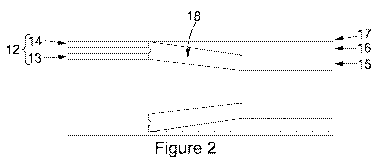
Figure 2 shows a transverse cross-section of a portion of the pipeline in the
region
marked by the box 11 in Figure lb. The illustrated portion includes a PIP
section 12
with an inner pipe 13 and an outer pipe 14, a single pipe section 15, a
thermal
insulation layer 16 (e.g. polymer foam), a coating (e.g. rubber or multi-layer
polymers)
17, and a transition piece 18. The load carrying structures, i.e. the inner
pipe 13, the
outer pipe 14 and the single pipe 15, are made of steel. The inner pipe 13 and
the
CA 03041635 2019-04-24
WO 2018/080312
PCT/N02017/050263
single pipe 15, which are in contact with the transported fluid, preferably
comprise a
corrosion resistant steel material.
The inner pipe 13 and the outer pipe 14 of the PIP 12 are both connected to
one side
5 of the transition piece 18, e.g. by welding. The other side of the
transition piece 18
connects, again for example by welding, to the single pipe section 15. The
single pipe
section 15 may have a wall thickness that provides a bending stiffness that
substantially matches that of the PIP section 12. Preferably, the bending
stiffness of
the single pipe cross-section may be within - 90%, - 80%, - 70%, - 50% of the
bending
stiffness of the PIP. The transition piece 18 has a bending stiffness in an
end region
adjacent to the PIP section 12 that substantially matches the bending
stiffness of the
PIP section 12, and a bending stiffness in an end region adjacent to the
single pipe 15
that substantially matches the bending stiffness of the single pipe 15. The
bending
stiffness of the transition piece 18 changes gradually, e.g. linearly, in an
intermediate
region between the end regions. The gradual change of bending stiffness
between the
PIP section 12 and the single pipe section 15 reduces strain concentrations
(strain
localization) during reeling. It therefore helps prevent damage to the
pipeline as it is
spooled, unreeled and straightened. Specific requirements on the bending
stiffness of
the transition piece 18 and single pipe section 15 depend on the reel 2,
straightener 4
and other installation conditions. For example, a reel with a greater radius
can
accommodate a larger difference in bending stiffness between sections of
different
pipes compared to a reel with a smaller radius.
In the embodiment shown in Figure 2, the single pipe cross-section 15 has an
external
thermal insulation layer 16. The thermal insulation layer 16 is such that the
insulated
single pipe section has thermal transmission properties similar to those of
the PIP
section 12. The thermal insulation coating 16 hence limits the temperature
gradient in
line with the flow close to the transition piece 18. Reduced
thermal insulation
properties occur for a limited length of the transition piece 18.
The pipeline, including both the PIP and single pipe sections, has a thin
protective
outer coating layer 17, so that the thin coating layer 17 forms an unbroken
outer sleeve
over the entire length of the pipeline. This outer coating layer may be of
rubber, multi-
layer polymers, insulation material: e.g. polymer foams.
CA 03041635 2019-04-24
WO 2018/080312
PCT/N02017/050263
6
The outer diameter of the PIP section 12 and the outer diameter of the
insulation layer
16 are approximately the same, in order to avoid any large discontinuity.
The
transition piece 18 accommodates a change from the inner diameter of the PIP
section
12 to the inner diameter of the single pipe 15. The change is preferably
small, in order
to allow for pigging and other types of inspection of the pipeline.
In a second embodiment of the invention, as illustrated in Figure 3, an
elastic coating
19 (e.g. an elastomeric polymer) covers the transition piece 18, extending
between the
PIP section and the thermal insulation layer 16. This coating 19 mitigates the
tendency
for cracks to form in the coating layer 17. The outer diameter of the elastic
coating 19
matches the outer diameter of the thin coating 17. The elastic coating 19
extends
laterally beyond the transition piece 18 to cover part of the PIP section 12
and the
single pipe section 15.
Figure 4 illustrates a method of deploying a pipeline in accordance with an
embodiment
of the invention. The figure includes the pipeline, as described above, being
reeled
onto a reel (step 20), at a deployment location, commencing unreeling of the
pipeline
(step 21), and at a terminating location cutting the single pipe section to
obtain the
correct pipeline length (step 22).
It will be appreciated by the person of skill in the art that various
modifications may be
made to the above described embodiments without departing from the scope of
the
invention. For example, the difference in the outer diameters of the PIP
section and
the single pipe section may be significant whilst minimising the difference in
the inner
diameters. This is accommodated by appropriate selections of wall thickness
and by
the design of the transition.
The inner diameter of the pipeline (the pipeline bore) may be different from
the inner
diameters of the PIP and the single pipe, by including several transition
pieces,
providing a gradual change in inner diameter.