Note: Descriptions are shown in the official language in which they were submitted.
HAIR STYLING DEVICE
RELATED APPLICATIONS
This application is a divisional of Canadian Patent Application No. 2,817,853
having a filing
date of May 14, 2013, and which claims priority to United Kingdom Application
No.
GB1021458.3, filed on December 17, 2010.
FIELD OF THE INVENTION
This invention relates to a hair styling device, and in particular to an
improvement upon
the hair styling device disclosed in W02009/077747.
For brevity, in the present application reference is made to the styling of a
female's hair,
but the invention is not limited thereby.
BACKGROUND TO THE INVENTION
The hair styling device described in W02009/077747 has a rotatable element
which
collects a length of hair to be styled, and winds the length of hair around an
elongate
member. The preferred embodiments described in W02009/077747 utilise a chamber
surrounding the elongate member, the chamber being heated by way of heat
applied to
the walls of the chamber and/or to the elongate member. The hair within the
chamber
becomes styled by the application of heat whilst it is located around the
elongate member.
The present invention shares many of the features of the preferred embodiments
of the
hair styling device described in W02009/077747,
which is believed to represent the closest prior art to the present invention.
CA 3041716 2019-04-30
2
SUMMARY OF THE INVENTION
Notwithstanding the practical and commercial attractiveness of the hair
styling
devices described in W02009/077747, the present inventors have conceived
certain improvements and the present invention is directed to those
improvements.
According to a first aspect of the present invention, there is provided a hair
styling
device having:
a body defining a chamber adapted to accommodate a length of hair, the chamber
having a primary opening through which the length of hair may pass into the
chamber; a rotatable element adapted to engage the length of hair adjacent to
the
primary opening;
an elongate member around which, in use, the length of hair is wound by the
rotatable element, the elongate member having a free end;
the chamber having a secondary opening through which the length of hair may
pass out of the chamber, the secondary opening being located adjacent to the
free end; and
a movable abutment which can engage the length of hair in use, the movable
abutment having an open position in which the length of hair can pass through
the
secondary opening, and a closed position in which the length of hair is
retained
within the chamber.
The present invention therefore shares a feature of the hair styling device of
W02009/077747 in having a (primary) opening through which the length of hair
passes into the chamber; the present invention differs in having a secondary
opening adjacent to a free end of the elongate member. This permits the length
of hair to be removed from the chamber without passing back through the
primary
opening.
Desirably, the secondary opening is annular and surrounds the free end of the
elongate member. Such a secondary opening permits a formed curl to be slid off
the end of the elongate member without being uncurled.
CA 3041716 2019-04-30
3
The inventors have realised that the avoidance of a requirement to force a
wound
curl to unwind as it is removed from the hair styling device has significant
benefits
in terms of the hair styling. Thus, since the chamber and therefore the hair
is still
hot as it is pulled out of the chamber, the hair continues to be styled as it
is
removed from the chamber, and a significant proportion (perhaps around 25% for
example) of the curvature of a wound curl can be lost as the length of hair is
pulled out of the chamber, despite the hair being subjected to only a small
force
during such removal.
The secondary opening can be permanently connected to the primary opening
whereby a length of hair can pass from the primary opening to the secondary
opening during operation of the device. The movable abutment can be located
within the secondary opening whereby directly to prevent a wound length of
hair
from passing out of the chamber until the end of a styling operation.
Alternatively,
the movable abutment can be located within the primary opening, or between the
primary and secondary openings. In these alternative embodiments the movable
abutment can hold the length of hair away from the secondary opening until the
end of a styling operation, and thereby indirectly prevent a wound length of
hair
from passing out of the secondary opening. Thus, it will be understood that
the
primary and secondary openings must be connected together if the length of
hair
is to enter the chamber through the primary opening and leave the chamber
through the secondary opening, but it is not necessary that the openings are
permanently interconnected.
According to a second aspect of the present invention, there is provided a
hair
styling device having:
a body defining a chamber adapted to accommodate a length of hair, the chamber
having a primary opening through which the length of hair may enter the
chamber;
a rotatable element adapted to engage the length of hair adjacent to the
primary
opening;
an elongate member around which, in use, the length of hair is wound by the
rotatable element;
CA 3041716 2019-04-30
4
a movable panel having a closed position and an open position, the movable
panel in the closed position overlying the primary opening, the movable panel
having a pressing part which acts to press a portion of the length of hair
towards
the primary opening.
Whilst W02009/077747 discloses an embodiment utilising a movable (door) panel
to close off the (primary) opening, that document did not also disclose the
use of a
pressing part of the panel acting to press the hair towards the opening.
to Desirably, the movable panel has two pressing parts, the pressing parts
being
spaced apart along the length of the primary opening. Desirably also, the
device
includes at least one inclined surface located adjacent to the primary
opening, the
movable panel being designed to cover the inclined surface(s) in its closed
position, with the respective pressing parts lying adjacent to the inclined
surface(s). In this way, as the panel is moved towards its closed position the
pressing parts will drive the length of hair across the inclined surface(s)
towards
the primary opening, to better ensure that all of the hair is engaged and
collected
by the rotatable element. There may be two inclined surfaces, for example, the
inclined surfaces converging towards the primary opening.
According to a third aspect of the present invention, there is provided a hair
styling
device having:
a body defining a chamber adapted to accommodate a length of hair, the chamber
having a primary opening through which the length of hair may pass;
a rotatable element adapted to engage the length of hair adjacent to the
primary
opening;
an elongate member around which, in use, the length of hair is wound by the
rotatable element;
a handle by which the device may be gripped by a user, the handle comprising a
fixed handle part and a movable handle part, the fixed handle part being
connected to the body and the movable handle part being movable relative
thereto.
CA 3041716 2019-04-30
5
It is preferably arranged that the movable panel is connected to the movable
handle part, so that a user can move the panel to its closed position simply
by
moving the movable handle part towards (or preferably into engagement with)
the
fixed handle part.
Desirably, the device is activated when the movable panel is moved to its
closed
position, i.e. the device carries a switch which is automatically actuated
when the
movable handle part reaches a predetermined position relative to the fixed
handle
part, or when the movable panel (or pressing part) reaches a predetermined
to position relative to the body. In this way, the device will not operate
(and in
particular the rotatable element will not move any of the length of hair)
until the
panel is in its closed position. As above indicated, pressing part(s) can act
to
press the length of hair towards the primary opening as the panel is moved
towards its closed position, so increasing the likelihood that all of the hair
is
is engaged and collected by the rotatable element. This reduces the likelihood
of
the hair becoming entangled, as entanglement is understood to occur only if
the
rotatable element engages and collects a portion of a length of hair but does
not
collect another portion of the length of hair.
20 According to a fourth aspect of the present invention, there is provided a
hair
styling device having:
a body defining a chamber adapted to accommodate a length of hair, the chamber
having a primary opening through which the length of hair may pass;
a rotatable element adapted to engage the length of hair adjacent to the
primary
25 opening;
an elongate member around which, in use, the length of hair is wound by the
rotatable element;
the body carrying at least one sensor adapted to detect misplaced hair.
30 For example, the end of an inclined surface opposed to the primary opening
can
carry a sensor which cooperates with the movable panel. The sensor is adapted
to detect the presence of hair between the end of the inclined surface and the
panel when the panel is in its closed position, it being determined that hair
in such
CA 3041716 2019-04-30
6
location might not be engaged and collected by the rotatable element and
therefore might be likely to lead to entanglement.
According to a fifth aspect of the present invention, there is provided a hair
styling
device having:
a body defining a chamber adapted to accommodate a length of hair, the chamber
having a primary opening through which the length of hair may pass;
a rotatable element adapted to engage the length of hair adjacent to the
primary
opening;
to an elongate member around which, in use, the length of hair is wound by the
rotatable element;
a control system which includes means to detect the load applied to the length
of
hair.
is The present invention shares the benefits of W02009/077747 in not applying
tension to the length of hair during the styling process, so that the force
required
to rotate the rotatable element will be relatively small. However, if a
portion of the "
length of hair becomes entangled the force will increase significantly, and
this can
be detected either by an increase in the current drawn by the motor, or
preferably
20 in a reduction in speed of the motor. The control system can be configured
to
react to a speed reduction (or load increase) above a certain threshold by
reversing the rotation of the rotatable element.
In embodiments in which the rotatable element has a predetermined starting
25 position, the control system can preferably reverse the rotatable element
until it
reaches the starting position. By arranging for the rotatable element to
reverse,
tension which has been put into the length of hair due to the entanglement
will be
relieved, and the tangled length of hair can be removed from the device (by
way
of the primary and/or secondary openings).
CA 3041716 2019-04-30
7
BRIEF DESCRIPTION OF THE PREFERRED EMBODIMENTS
The invention will now be described in more detail, by way of example, with
reference to
the accompanying drawings, in which:
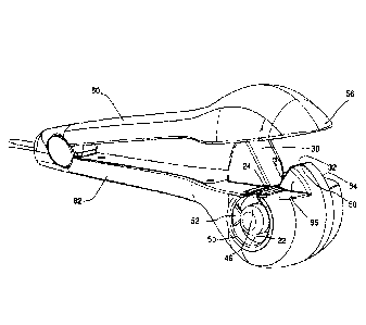
Fig.1 shows a perspective view of a part of the hair styling device according
to the
present invention, with some of the body removed, and with a length of hair
placed adjacent to the primary opening;
Fig.2 shows the hair styling device of the invention including all of the
body, in its
condition ready to receive a length of hair to be styled;
Fig.3 shows the hair styling device in its condition during hair styling
(although the
length of hair is omitted from the drawing);
Fig.4 shows a perspective view from below, -including details of the panel and
its
pressing parts; and
Fig.5 shows another perspective view of the hair styling device.
DETAILED DESCRIPTION
A brief description of the operation of the device is provided in relation to
Fig.1, so as to
clarify the distinctions over the disclosure of W02009/077747.
The hair styling device 10 has a body 12 and a handle 14. Within the body 12
is a
chamber 16. An elongate member 20 is located within the chamber 16, the
diameter of
the elongate member 20, and the diameter of the wall 22 of the chamber, being
chosen
to produce curls of the desired curvature. (It will be understood that the
elongate
member 20, and the chamber 16, need not be of
CA 3041716 2019-04-30
8
circular cross-section, and so the reference to "diameter" refers only to
those
circular embodiments).
The body 12 has a primary opening 24 (Fig.2) through which a length of hair 26
may be introduced into the chamber 16. The introduction of a length of hair 26
into the device is facilitated by a pair of inclined surfaces 30 and 32, which
lie to
opposed sides of the primary opening 24. Only a part of each inclined surface
30
and 32 is shown in Fig.1, the complete inclined surfaces 30 and 32 are shown
in
Fig.2.
The device has a rotatable element 34 which can be driven to rotate about a
longitudinal axis A-A. The rotatable element 34 projects beyond the primary
opening 24, and the inclined surfaces 30 and 32 have cut-outs 36 formed
therein
to accommodate the rotatable element 34 during its rotation.
In this embodiment the longitudinal axis A-A around which the rotatable
element
34 rotates is coincident with the axis of the elongate member 20, but that is
not
necessarily the case. Also, in this embodiment the elongate member 20 is fixed
relative to the body 12, i.e. it does not rotate with the rotatable element,
but that is
also not necessarily the case, and in other embodiments the elongate member 20
rotates with the rotatable element.
As the rotatable element 34 rotates (counter-clockwise as drawn in Fig.1), its
leading end 28 passes over the length of hair 26 which lies adjacent to the
primary opening 24, and its leading edge 38 (which is arcuate in this
embodiment)
engages and captures the length of hair 26. The form of the rotatable element
34
is such that it pulls the length of hair 26 through the primary opening 24 and
into
the chamber 16.
Considering the length of hair 26 shown in Fig.1, the end 40 is the free end
of the
length of hair, and the part 42 is connected to the user's head (not shown).
The
hair styling device 10 is intended to impart curls to substantially all of the
length of
hair 26 lying between the part 42 and the free end 40, so that the numeral 42
CA 3041716 2019-04-30
9
represents the "end" of the length of hair 26 which will be styled by the
device.
Each of the individual hairs in the length of hair 26 will be connected to the
user's
scalp.
As the rotatable element 34 rotates, the distal portion of the length of hair
26
(which lies between the rotatable element 34 and the free end 40), is pulled
through the primary opening 24 to the far side of the rotatable element as
drawn
in Fig.1 (to the right of the rotatable element as drawn in Fig.5). As shown
in
Fig.5, the primary opening 24 has a closed end 48 which provides a relatively
to fixed surface and it is the relative rotation between the rotatable element
34 and
the primary opening 24 (and in particular its closed end 48) which causes the
hair
to be drawn into the device 10.
In this embodiment, the primary opening 24 is connected by a passageway 46
(Fig.2) to a secondary opening 50. When the rotatable element 34 is rotated,
the
proximal portion of the length of hair (which lies between the rotatable
element 34
and the part 42), will also be pulled through the primary opening 24 and into
the
chamber 16, to the near side of the rotatable element as viewed in Fig.1 (to
the
left of the rotatable element as drawn in Fig.5). In particular, the proximal
portion
is pulled through the primary opening 24, through the passageway 46, and
subsequently through the secondary opening 50 to lie adjacent to the elongate
member 20. Continued rotation of the rotatable element 34 drives the proximal
portion of the length of hair 26 to rotate around the elongate member 20 until
it
engages the abutment 52 (Figs.2,3).
In common with the hair styling devices of W02009/077747, the hair is not
clamped by any part of the device 10. The part 42 of the length of hair 26 is,
however, substantially fixed in position relative to the device 10.
Accordingly, as
the rotatable element 34 continues to rotate, the distal portion of the length
of hair
26 is gradually pulled from the far side of the rotatable element 34 to the
near
side, as drawn in Fig.1, until eventually all of the length of hair 26 is
wound around
the elongate member 20 between the rotatable element 34 and the abutment 52.
It will be understood that it is the relative rotation between the rotatable
element
CA 3041716 2019-04-30
34 and the abutment 52 which causes the distal portion of the length of hair
to be
drawn from the far side of the rotatable element to the near side of the
rotatable
element as drawn in Fig.1.
The chamber 16 is preferably heated, either directly by way of one or more
heating elements within the elongate member 20 and/or within the wall 22 of
the
chamber 16, or indirectly by way of hot air directed into the chamber 16,
perhaps
by a separate hair dryer. Other suitable means of generating heat can
alternatively be used to heat the chamber indirectly, for example microwave
radiation or electrical induction.
The panel 56 is connected to a "movable" handle part 60 which is hinged to a
"fixed" handle part 62 (Fig.2). The movable handle part 60 can be moved
relative
to the fixed handle part 62, and thereby the panel 56 can be moved relative to
the
is body 12, between the open position shown in Figs.1,2,4 and 5 and the closed
position shown in Fig.3. In this preferred embodiment the movable handle part
60
is resiliently biased away from the fixed handle part 62, so that the user
must
clamp the handle parts 60 and 62 together in order to move the panel 56 to the
closed position, and to retain it in that position during the styling
procedure.
The hair styling device 10 is therefore particularly suited for use by a
person
styling her own hair, the user grasping the length of hair 26 with one hand
and
grasping (and operating) the hair styling device 10 with the other hand. The
ability
to grasp and manipulate the hair styling device 10 with one hand will also be
advantageous for hairdressers and the like when using the device to style
another
person's hair.
When the length of hair 26 has been styled, for example by remaining within
the
heated chamber 16 for a predetermined length of time, the user can relax the
grip
upon the handle parts 60 and 62, permitting the resilient bias to move the
panel
56 away from the body 12. In this embodiment it is arranged that the abutment
52
is spring-biased to its "open" position, and is driven to its "closed"
position as the
handle part 60 is moved towards the handle part 62. Accordingly, as the handle
CA 3041716 2019-04-30
11
parts 60 and 62 are separated at the end of a styling operation, the abutment
52
automatically moves from the closed position shown in Figs. 2 and 3 to its
open
position. It is arranged that the abutment 52 in its open position allows the
styled
length of hair to pass out of the secondary opening 50, i.e. to slide along
the
elongate member 20 towards and subsequently off its free end. Little force is
required to separate the hair styling device 10 from the length of hair which
has
been styled, and because the secondary opening 50 is annular and surrounds the
elongate member 20 the length of hair is not required to pass any obstruction
or
otherwise be forced to uncurl during its removal from the hair styling device
10, so
to that the curvature of the curls created by the device can be substantially
maintained.
It has been recognised that the most significant likelihood of entanglement of
the
length of hair 26 is caused by a portion of the length of hair 26 being
captured by
the rotatable element 34, and another portion of the length of hair 26 not
being
captured by the rotatable element. In such circumstances the captured portion
becomes wound around the elongate member 20 whereas the uncaptured portion
does not. The present invention seeks to reduce the likelihood of such
entanglement by increasing the likelihood that all of the length of hair 26 is
captured by the rotatable element 34.
This is achieved at least in part by the provision of the inclined surfaces 30
and
32, which serve to guide the length of hair towards the primary opening 24.
Additionally, the length of hair 26 is driven along the inclined surfaces,
towards the
primary opening 24, by pressing parts 54 (Fig.4) located on the underside of
the
panel 56.
In this embodiment, it is arranged that the device is actuated automatically
when
the panel 56 is moved to its closed position, i.e. in addition to the abutment
52
being moved to its closed position, the rotatable element 34 begins to rotate,
and
the heating element(s) (not shown) are activated whereby to heat the chamber
16,
when the handle parts 60 and 62 are brought together.
CA 3041716 2019-04-30
12
In other embodiments the handle part 60 or 62 can carry a switch for manual
actuation of the device, the switch either having a single position in which
the
abutment 52 is moved to its closed position, the rotatable element 34 is
rotated,
and the heating element(s) are activated, or else separate sequential
positions for
each of these operations. In these embodiments it is preferably arranged that
at
least the rotatable element 34 cannot be rotated unless the panel 56 is in its
closed position.
It is arranged that when the panel 56 is in its closed position as shown in
Fig.3,
to the pressing parts 54 lie close to the primary opening 24. The pressing
parts 54
are spaced apart along the longitudinal axis A-A by a distance only slightly
greater
than the width of the inclined surfaces 30, 32, so that in the closed position
the
pressing parts lie close to the opposed sides 64, 66 of the inclined surfaces.
In
fact, as seen in Fig.4, in this embodiment the pressing parts 54 surround a
recess
68 in the panel 56 which is sized to accommodate the inclined surfaces 30 and
32
and the associated parts of the body 12.
It will therefore be understood that any of the length of hair 26 lying
adjacent to
the inclined surfaces 30,32 when the panel 56 is in its open position, will be
driven
by the pressing parts 54 along the inclined surfaces towards the primary
opening
24 as the panel 56 is moved to its closed position. The length of hair 26 will
therefore be held adjacent to the primary opening 24 as the rotatable element
begins to rotate, whereby the likelihood of any portion of the length of hair
not
being captured by the rotatable element 34 is much reduced or eliminated.
It has been recognised that a portion of the length of hair might not be
captured by
the rotatable element 34 if it is placed beyond the end of the inclined
surface 32.
This might for example occur when the user is seeking to style her own hair
and is
unsighted, perhaps whilst styling the hair at the back of her head for
example. In
some embodiments of the invention, the body 12 can carry one or more sensors,
suitably optical sensors, which can detect the presence of hair in unsuitable
locations, and can prevent operation of the device until the misplaced hair is
removed. In the embodiment shown, an optical transmitter 58 is positioned
CA 3041716 2019-04-30
13
adjacent to the extreme end of the inclined surface 32, and a corresponding
detector (not seen) is positioned on the underside of the panel 56. When the
panel is closed any misplaced hair between the transmitter 58 and detector can
prevent actuation of the rotatable element and cause the issuance of a warning
signal to the user.
Reference is made above to the use of a sensor on the inclined surface 32, and
it
will be understood that in some embodiments it may be advantageous to provide
one or more sensors also on the inclined surface 30. In the present
embodiment,
to however, it is arranged that the separation of the handle parts
60,62 in their open
position is insufficient to move the panel 56 away from the inclined surface
30
(alternatively stated, even when the handle parts 60 and 62 are in the fully
open
position as shown in Figs. 1, 2, 4 and 5 the top of the inclined surface 30
still lies
within the recess 68). The likelihood of any of the length of hair 26 being
placed
at or beyond the top of the inclined surface 30 is therefore very small. In
some
embodiments the top of the inclined surface can be shaped so as to reduce the
likelihood of any of the length of hair 26 passing over the top of the
inclined
surface 30; the user may therefore press the length of hair against the
inclined
surface 30 in the knowledge that all of the length of hair will subsequently
be
captured by the rotatable element 34.
As stated above, the abutment 52 acts to prevent the proximal portion of the
length of hair 26 from rotating around the free end of the elongate member 20,
so
that the length of hair 26 is curled or wound around the elongate member 20
rather than simply being twisted as the rotatable element rotates. It will be
understood that it is not necessary for an abutment to close a part of the
secondary opening 50 in order to perform this function, and in an alternative
embodiment an abutment could be provided in the passageway 46, whereby to
separate the primary opening 24 from the secondary opening 50. In another
alternative the abutment could be provided at the proximal end of the primary
opening 24, it being recognised that an abutment located anywhere between the
rotatable element and the free end of the elongate member will perform this
function.
CA 3041716 2019-04-30
14
If the abutment is located either in the passageway 46 or in the proximal end
of
the primary opening 24, it should be moved to its closed position before a
length
of hair is placed adjacent to the primary opening. The abutment should be
moved
to its open position (whereby to interconnect the primary and secondary
openings)
at the end of a styling operation, and in particular after the rotatable
element 34
has stopped rotating, for example as the handle parts 60 and 62 are separated.
The rotatable element 34 is shown in its starting position in Fig.1. It is
arranged
that the user can determine the number of rotations of the rotatable member
necessary to draw all of the length of hair 26 into the chamber 16. When all
of the
hair has been drawn into the chamber 16 and the user switches off the
rotatable
element 34, the rotatable element automatically continues to its starting
position.
It is another desirable feature of the hair styling device 10 that the device
can
automatically reverse the rotation of the rotatable element 34 in the event
that the
user's hair becomes entangled. For example, the control means of the device 10
(not seen) can measure the rate of rotation of the motor which drives the
rotatable
element 34. If the rate of rotation drops below a predetermined threshold this
will
indicate an unacceptable load being applied by the rotatable element, and the
possible entanglement of the user's hair. In such circumstances, the control
means can stop the rotatable element 34 and reverse it to the start position.
The
control means will also move the abutment member 52 to its open position. The
reverse rotation of the rotatable element 34 will release any tension which
has
been applied to the length of hair and when the tension has been removed the
length of hair can be removed from the device 10 and the entanglement
released.
It is not necessary that the rotatable element 34 reverse all of the rotation
which
has been imparted into the length of hair. If, for example, the rotatable
element
has undertaken three rotations before the control means detects entanglement,
it
will preferably still only be reversed to its starting position and will not
reverse past
that starting position whereby to seek to remove all of the curls. The reason
for
this is that it is only necessary to remove the unwanted tension in the length
of
CA 3041716 2019-04-30
15
hair for it to be removed from the device 10, and it will be easier to release
any
entanglement once the length of hair 26 has been removed from the device.
Seeking to remove all of the curls by reversing all of the rotations which
have
occurred will likely introduce more entanglement.
It will be understood that the secondary opening 50 could in an alternative
embodiment be partially or fully closed by a part of the panel 56, i.e. the
panel 56
could carry a projection which overlies the secondary opening. That is not
preferred, however, as it is expected that the projection would have to be a
very
ro close sliding fit over the free end of the elongate member 20 in order to
prevent
any of the length of hair passing therebetween; any hair which did pass around
the free end of the elongate member 20 would become twisted rather than
curled,
and would be liable to entanglement.
It will also be understood that the primary opening 24 does not need to remain
open during the styling procedure, and in an alternative embodiment the
primary
opening could be closed as the handle parts 60 and 62 are brought together. In
such an alternative embodiment the primary opening could be located at a
position approximately 90 clockwise from the position shown in Figs. 1 and 2
(i.e.
at the "3 o'clock" position relative to the elongate member 20 rather than the
"12
o'clock" position of Figs. 1 and 2). The panel and body could have cooperating
surfaces which define the primary opening when the device is in its open
condition, the cooperating surfaces being brought together (or to overlap)
when
the device is in its closed position. In such embodiments, a portion of the
length
of hair would be located within the chamber before the rotatable element
commences its rotation.
The present embodiment has two inclined surfaces 30 and 32, and it is expected
that a hair styling device for personal use will preferably include two
inclined
surfaces which converge towards the primary opening 24. In
another
embodiment only the inclined surface 30 is provided, it being possible for a
single
inclined surface to provide the necessary guidance for a skilled user to
position
the length of hair adjacent to the primary opening, even if the user cannot
see the
CA 3041716 2019-04-30
16
length of hair. In addition, for hair styling aids which are primarily
intended for
professional use, neither of the inclined surfaces 30 and 32 may be required.
CA 3041716 2019-04-30