Note: Descriptions are shown in the official language in which they were submitted.
DISINFECTING WIPES FLEX PACK CLOSURE
BACKGROUND OF THE INVENTION
1. The Field of the Invention
[0001] The present invention relates to packages or containers including
a flexible
(e.g., bag-like) body, with a hinged closure positioned over an opening in the
flexible
body through which wipes, tissues, or the like may be dispensed.
2. Description of Related Art
[0002] Wetted wipes including a cleaning formulation impregnated therein are
employed in a wide variety of circumstances for disinfecting or cleaning
various surfaces.
Because the wipes are typically pre-wetted with a cleaning formulation, it is
important
that the container be sealed so as to prevent the wipes from prematurely
drying out.
[0003] Such wipes may initially be interleaved with or otherwise
attached to one
another, by which they may in theory be easily separated from one another, as
a lead wipe
may be separated from the following wipe as it is pulled from the container.
In actual
practice, with existing dispensing configurations, there is often a tendency
for the lead
wipe to not fully separate from the following wipe as the lead wipe is pulled
from the
dispenser, leading to more than the single desired wipe being pulled through
the orifice
(referred to as "roping"). Such roping leads to waste, as more wipes than the
user intended
end up being dispensed from the container.
[0004] Similarly, often even if separation of the lead wipe does occur
from the
subsequent wipe, the subsequent wipe is pulled sufficiently from the package
that it
- 1 -
Date Recue/Date Received 2020-12-03
becomes difficult to close the hinged closure so that the consumer must
manipulate the
retained wipe out of the way of the closure mechanism, to achieve a good seal.
[0005] Another issue with existing configurations is the tendency for
the lead wipe to
fall back into the container, requiring the user to retrieve the lead wipe and
rethread it
through the orifice and/or any retention mechanism associated with the orifice
(referred
to as "fallback"). As a result, there continues to be a need for improved wipe
dispenser
configurations that may alleviate one or more of these or other issues.
BRIEF SUMMARY
[0006] In an embodiment, the present invention is directed to a wipes
dispenser (e.g.,
a package of wipes) including a flexible container comprising a flexible
container body
(e.g., a thin film plastic packaging) having an opening through which wipes
may be
dispensed. The flexible container body defines an interior region containing a
plurality
of wipes (e.g., configured as a rectangular stack of wipes) that may be
interfolded,
interleaved, or otherwise interconnected such that pulling on a lead end of a
lead wipe of
the plurality of wipes causes a following wipe to also be pulled and follow
the lead wipe.
The wipes dispenser further includes a closure positioned over the opening of
the flexible
container body which is configured to allow a user to selectively open and
close access
to the opening. The closure may include a perimeter flange which is sealed to
the flexible
container body, a base defined within the perimeter flange which initially
covers the
opening through the flexible container body, and a tear-away orifice covering
(e.g., a
frangible portion of the base) that is defined in the base of the closure. A
shape of the
tear-away orifice covering includes a tear-away perimeter that follows a
pathway that
- 2 -
Date Recue/Date Received 2020-12-03
forms an angle that is greater than 90 relative to a direction of pull as the
tear-away
orifice covering is torn away from the base. In other words, as the tear-away
covering is
pulled away, there is a point in the progression of the removal of the
covering where the
direction that the orifice is expanding in actually moves backwards (i.e.,
greater than 90 ),
towards where the tear-away covering initially began to be peeled away.
[0007]
Another embodiment is directed to a wipes dispenser including a flexible
container comprising a flexible container body (e.g., a flexible package of
wipes) having
an opening through the flexible container body through which wipes may be
dispensed.
The flexible container body defines an interior region containing a plurality
of wipes (e.g.,
in a rectangular stack configuration). The plurality of wipes may be
interfolded,
interleaved, or otherwise interconnected such that pulling on a lead end of a
lead wipe of
the plurality of wipes causes a following wipe to also be pulled and follow
the lead wipe.
A closure is provided over the opening of the flexible container body which is
configured
to allow a user to selectively open and close access to the opening. The
closure includes
a perimeter flange which is sealed to the flexible container body, a base
defined within
the perimeter flange which initially covers the opening through the flexible
container
body, and a tear away orifice covering defined in the base of the closure. The
tear-away
orifice covering is in a particular shape that follows a pathway forming an
angle that is
greater than 90 (at at least some point) relative to a direction of pull as
the tear-away
covering is torn away from the base. A hinged cover may be provided,
selectively
closable over the base of the closure. The entire closure (e.g., the hinged
cover, the
perimeter flange, and the base with its tear-away orifice covering) may be
formed as a
single piece of material (e.g., injection molded as a single, integral piece
of material). No
- 3 -
Date Recue/Date Received 2020-12-03
additional structures may be interposed between the single piece closure and
the plurality
of wipes in the flexible container body. For example, no separate orifice
defining member
in addition to the orifice of the single piece closure may be disposed between
the wipes
and the closure as the wipes are pulled through the opening in the flexible
container body.
This is advantageous over embodiments that employ a multi-piece closure, where
a
separate piece defining the orifice is provided, which separate pieces require
assembly.
Rather, in the present embodiments, the wipes are pulled through the opening
in the film
material of the flexible body container, and through an orifice that is
provided by the
single piece injection molded closure.
[0008]
Another embodiment relates to a method of use (e.g., for opening a wipes
dispenser and dispensing wipes therefrom). Such a method may include providing
a
wipes dispenser such as those described herein, and pulling a pull-tab
associated with the
tear-away orifice covering defined in the base of the closure of the wipes
dispenser. The
tear away perimeter may follow a pathway that extends backwards, at an angle
greater
than 900, towards an initial location of the pull-tab, during at least a
portion of the period
as the tear-away orifice covering is torn away from the base, so as to create
an orifice in
the base having the shape of the tear-away orifice covering. Once the orifice
has been
created by removal of the tear-away covering, a lead wipe from the plurality
of wipes can
be pulled through the orifice in the closure. The particular orifice
geometries disclosed
herein, including an angle of greater than 90 relative to the direction of
pull, have been
found to advantageously decrease or resist roping of wipes, and/or to decrease
or resist
fallback of the following wipe back through the orifice. The presently
described
embodiments present an improvement over existing orifice configurations,
better striking
- 4 -
Date Recue/Date Received 2020-12-03
the desired delicate balance between reducing roping (leading to waste as more
than one
wipe at a time is dispensed) and reducing fallbacks (which is frustrating, as
it requires the
user to again separate the leading edge of the lead wipe in preparation to
pulling it from
the dispenser).
[0009] What is ideally desired is that upon pulling the lead wipe from
the dispenser,
that only the lead wipe be dispensed, and that the following wipe (which
becomes the
next lead wipe) thread itself through the orifice in a manner that the leading
end thereof
is separated from the remainder of the wipe, poised for easy dispensing the
next time a
wipe is wanted, where the threaded wipe does not occlude closing of a hinged
cover over
the wipe threaded through the orifice.
[0010] Further features and advantages of the present invention will
become apparent
to those of ordinary skill in the art in view of the detailed description of
preferred
embodiments below.
BRIEF DESCRIPTION OF THE DRAWINGS
[0011] To further clarify the above and other advantages and features of
the present
invention, a more particular description of the invention will be rendered by
reference to
specific embodiments thereof which are illustrated in the drawings located in
the
specification. It is appreciated that these drawings depict only typical
embodiments of the
invention and are therefore not to be considered limiting of its scope. The
invention will
be described and explained with additional specificity and detail through the
use of the
accompanying drawings in which:
- 5 -
Date Recue/Date Received 2020-12-03
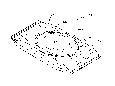
[0012] FIG. 1 is a perspective view of an exemplary wipes dispenser
configured as a
flexible package according to the present invention;
[0013] FIG. 2 is a perspective view similar to that of FIG. 1, with a
hinged cover of
the closure of the wipes dispenser opened, showing the base and tear-away
orifice
covering thereunder;
[0014] FIG. 3 is a top plan view of the base and tear-away orifice
covering of FIG. 2,
with the hinged cover not being shown;
[0015] FIG. 4 shows a user beginning to pull the tear-away orifice
covering out of the
base;
[0016] FIG. 5 shows the base with the tear-away orifice covering having
been
removed;
[0017] FIG. 6 shows a user beginning to pull a lead end of a lead wipe
through the
orifice;
[0018] FIG. 7 shows the following wipe threaded through the orifice,
once the lead
wipe has been pulled from the orifice;
[0019] FIG. 8A illustrates an enlarged plan view of the base, the tear-
away orifice
covering, and the pull-tab of the closure shown in FIG. 1 other orifice
geometries
according to the present invention;
[0020] FIG. 8B is a view similar to that of FIG. 8A, in which the pull-
tab is being
pulled, beginning to remove the tear-away orifice covering, similar to FIG. 4;
[0021] FIG. 9A is a cross-sectional view through the configuration shown
in FIG. 8A;
[0022] FIG. 9B is a cross-sectional view through the configuration shown
in FIG. 8B;
- 6 -
Date Recue/Date Received 2020-12-03
[0023] FIGS. 10A and 10B illustrate other orifice geometries according
to the present
invention;
[0024] FIG. 11 charts peak or maximum force for dispensing a wipe from various
wipes dispensers at the beginning of a package, the middle of a package, and
the end of
a package (i.e., the last wipes in the package);
[0025] FIG. 12 charts the standard deviation of pull forces during the
pull of a single
wipe, corresponding to the smoothness of pull, for dispensing wipes from
various wipes
dispensers at the beginning of the package, the middle of the package, and the
end of the
package;
[0026] FIG. 13 charts the average force to dispense a wipe from various
wipes
dispensers at the beginning of the package, the middle of the package, and the
end of the
package;
[0027] FIG. 14 is a dotplot charting roping results for various tested
wipes dispensers;
[0028] FIG. 15 is an interval plot at a 95% confidence interval (95% CI)
for the same
roping results shown in FIG. 14;
[0029] FIG. 16 is a dotplot charting fallback results for various tested
wipes
dispensers; and
[0030] FIG. 17 is an interval plot at a 95% confidence interval (95% CI)
for the same
fallback results shown in FIG. 16.
- 7 -
Date Recue/Date Received 2020-12-03
DETAILED DESCRIPTION OF THE PREFERRED EMBODIMENTS
I. Definitions
[0031] Before describing the present invention in detail, it is to be
understood that this
invention is not limited to particularly exemplified systems or process
parameters that
may, of course, vary. It is also to be understood that the terminology used
herein is for
the purpose of describing particular embodiments of the invention only, and is
not
intended to limit the scope of the invention in any manner.
[0032] The term "comprising" which is synonymous with "including,"
"containing,"
or "characterized by," is inclusive or open-ended and does not exclude
additional,
unrecited elements or method steps.
[0033] The term "consisting essentially of' limits the scope of a claim
to the specified
materials or steps "and those that do not materially affect the basic and
novel
characteristic(s)" of the claimed invention.
[0034] The term "consisting of' as used herein, excludes any element,
step, or
ingredient not specified in the claim.
[0035] It must be noted that, as used in this specification and the
appended claims, the
singular forms "a," "an" and "the" include plural referents unless the content
clearly
dictates otherwise. Thus, for example, reference to a "surfactant" includes
one, two or
more surfactants.
[0036] Numbers, percentages, ratios, or other values stated herein may
include that
value, and also other values that are about or approximately the stated value,
as would be
appreciated by one of ordinary skill in the art. A stated value should
therefore be
interpreted broadly enough to encompass values that are at least close enough
to the stated
- 8 -
Date Recue/Date Received 2020-12-03
value to perform a desired function or achieve a desired result, and/or values
that round
to the stated value. The stated values include at least the variation to be
expected in a
typical manufacturing or formulation process, and may include values that are
within
10%, within 5%, within 1%, etc. of a stated value. Furthermore, the terms
"substantially",
"similarly", "about" or "approximately" as used herein represent an amount or
state close
to the stated amount or state that still performs a desired function or
achieves a desired
result. For example, the term "substantially" "about" or "approximately" may
refer to an
amount that is within 10% of, within 5% of, or within 1% of, a stated amount
or value.
[0037] Some ranges may be disclosed herein. Additional ranges may be
defined
between any values disclosed herein as being exemplary of a particular
parameter. All
such ranges are contemplated and within the scope of the present disclosure.
[0038] Unless defined otherwise, all technical and scientific terms used
herein have
the same meaning as commonly understood by one of ordinary skill in the art to
which
the invention pertains. Although a number of methods and materials similar or
equivalent
to those described herein can be used in the practice of the present
invention, the preferred
materials and methods are described herein.
II. Introduction
[0039] The present invention is directed to wipes dispensers from which
wipes may
be dispensed one at a time as a lead wipe of a plurality of interconnected
wipes is pulled
from the flexible container or package (used interchangeably herein), becoming
separated
from the following wipe as it is dispensed. An exemplary wipes container may
include a
flexible container body having an opening through the flexible container body
through
which wipes are dispensed. The flexible container body may be formed of a
thin, film
- 9 -
Date Recue/Date Received 2020-12-03
polymeric material. The flexible container body defines an interior region
containing a
plurality of wipes (e.g., positioned therein as a rectangular stack of wipes)
that are
interconnected such that pulling on a lead end of a lead wipe of the plurality
of wipes
causes a following wipe to also be pulled and follow the lead wipe. By way of
example,
the plurality of wipes may be configured as a "pack" in which adjacent wipes
are stacked,
cross-folded, interfolded, interleaved, or otherwise interconnected so that
pulling on a
lead end of a lead wipe causes a following wipe to also be pulled and follow
the lead
wipe. Any desired configuration of stacking the wipes may be employed.
Numerous
such possible configurations will be apparent to those of skill in the art in
light of the
present disclosure. Non-limiting examples of such interconnected stacking of
wipes are
disclosed in U.S. Publication 2016/0031632. Other possible configurations will
be
apparent to those of skill in the art.
[0040]
The wipes dispenser farther includes a closure (e.g., relatively rigid as
compared to the thin film material of the flexible container body) positioned
over the
opening of the flexible container body, which closure is configured to allow a
user to
selectively open and close access to the opening. The closure thus seals the
opening when
closed, e.g., preventing the wipes from drying out (e.g., where they are pre-
moistened
with a desired treatment composition), and also preventing dirt and debris
from entering
the dispenser and contaminating the wipes. Such closure may include a
perimeter flange
which is sealed to the flexible container body, a base defined within the
perimeter flange
which initially covers the opening through the flexible container body, and a
tear-away
orifice covering defined in the base of the closure. The tear-away covering
(e.g., a
frangible member of the base) includes a shape including a tear-away perimeter
that
- 10 -
Date Recue/Date Received 2020-12-03
follows a pathway that forms an angle that is greater than 900 relative to a
direction of
pull employed as the tear-away covering is torn away from the base. The
orifice forms
as a result of the tear-away covering being torn away. A hinged cover may be
provided
as part of the closure, so as to selectively close over the orifice in the
base (and opening
through the flexible film material of the flexible container body thereunder).
III. Exemplary Wipes Dispensers
[0041] FIG. 1 shows an exemplary wipes dispenser 100 including a
flexible container
body 102 having an opening through which wipes may be dispensed. By way of
example,
flexible container body 102 may comprise a thin film polymeric material such
as
polypropylene, polyethylene, other polymers, or the like. Combinations of such
materials
may also be suitable for use. Such thin flexible polymeric materials may
typically be less
than 0.5 mm in thickness (e.g., less than 0.4 mm, less than 0.3 mm, from 0.01
mm to 0.3
mm, from 0.05 mm to 0.3 mm, or from 0.1 mm to 0.3 mm). In part because of
their
thinness, such materials are very flexible. In some embodiments, the flexible
container
body 102 may be in a generally rectangular shape, as apparent from FIG. 1, as
opposed
to a canister or plastic tub, which configurations are formed from relatively
thicker
materials, and while possibly exhibiting some flexibility, are not flexible to
the degree as
"flex packs" such as those illustrated in FIG. 1. Of course, while described
principally in
the context of such "flex packs", it will be appreciated that the closures
described herein
could conceivably be employed with canisters, plastic tubs, or other
containers, in some
embodiments.
[0042] Wipes dispenser 100 further includes a closure 104 positioned
over the opening
of the flexible container body 102, which is configured to allow a user to
selectively open
- 11 -
Date Recue/Date Received 2020-12-03
and close access to the opening. Closure 104 is illustrated as including a
perimeter flange
106 which may be heat-sealed or otherwise sealed to flexible container body
102. In the
illustrated embodiment, flange 106 is sealed to an interior surface of the
flexible container
body 102, i.e., it is shown being disposed under the film material of flexible
container
body 102, e.g., being heat sealed, secured with an adhesive, or otherwise
sealed thereto,
to provide an air-tight and water-tight seal therebetween.
[0043] As shown in FIG. 2, closure 104 includes a base 108 defined
within perimeter
flange 106. Base 108 initially covers the opening through flexible container
body 102,
through which the wipes will be dispensed. Closure 104 also includes a tear-
away orifice
covering 110 defined in base 108 of closure 104. Tear-away orifice covering
110 may
be a frangible member of base 108 which is configured to be torn away from
base 108
when it is desired to access the wipes within dispenser 100. As shown in FIG.
3, the tear-
away orifice covering 110 is in a particular shape which includes a perimeter
112 that
follows a pathway that forms an angle that is greater than 90 relative to a
direction of
pull (P) as the tear-away covering 110 is torn away from base 108. In other
words, the
shape of covering 110 (and the orifice 114 that results once covering 110 is
torn away)
includes at least one portion 116 that is angled (e.g., curved) backwards,
towards point
where removal of covering 110 begins (e.g., at tab 118). Portion 116 creates
an angle 0
greater than 90 relative to such direction of pull P. Enlarged FIGS. 8A-8B
perhaps best
illustrate this "backwards" greater than 90 angle.
[0044] As shown in FIGS. 2-3, a pull-tab 118 may be provided, attached
to covering
110, providing a convenient location which may be gripped by the user as
covering 110
is removed from base 108. For example, tab 118 may be configured as any member
- 12 -
Date Recue/Date Received 2020-12-03
which extends from covering 110, so as to be easily gripped, such as a ring,
or any other
shaped extension from covering 110. Along with all the other portions of
closure 104,
pull-tab 118 may be integrally molded with the remainder of closure 104 as a
single piece.
[0045] As
shown in FIGS. 1-2, a cover 134 may be hingedly connected (e.g., hinge
136) to the remainder of closure 104. For example, in an embodiment hinge 136
may
connect cover 134 to a portion of perimeter flange 106. Cover 134 may ensure a
user can
close the wipes dispenser 100 when not in use, e.g., to prevent wipes 128
within flexible
container body 102 from drying out, and to prevent dirt, debris, or other
unwanted
material from entering through the orifice and contaminating wipes 128 once
covering
110 has been removed.
[0046] FIGS. 3-5 and 8A-8B show an exemplary shape for covering 110 and the
resulting orifice 114. FIGS. 8A-8B are enlarged, perhaps showing these
features best.
By way of example, orifice 114 and covering 110 may include proximal and
distal
narrowed portions 120, e.g., aligned along latitudinal axis A, and a central
widened
portion 122 centered along longitudinal axis B. In some embodiments, the shape
of
covering 110 and orifice 114 may be symmetrical, e.g., exhibiting symmetry
along axis
A, along axis B, or both. As apparent, the covering 110 and resulting orifice
114 may
occupy only a relatively small fraction of the overall surface area of base
108 defined
within closure 104. For example, elliptical base 108 may extend beyond orifice
114, such
that orifice 114 and covering 110 only occupies no more than 50%, no more than
40%,
no more than 35%, no more than 30%, no more than 25%, or even no more than 20%
of
the surface area of the recessed base 108 (e.g., the recessed ellipse within
the center of
closure 104).
- 13 -
Date Recue/Date Received 2020-12-03
[0047] FIG. 3 shows the shape of covering 110, while FIG. 4 shows a user
grasping
pull-tab 118, beginning removal of covering 110, so as to form orifice 114 in
base 108.
It will be readily apparent that the tear-away orifice covering 114 may be in
the same
plane as base 108, being injection molded therewith, all as single piece of
plastic material.
The perimeter 112 between covering 110 and the remainder of base 108 (at
perimeter
112) may be thinned, rouletted, die cut, scored, or the like to cause
preferential separation
along perimeter 112, as covering 110 is pulled from base 108.
[0048] FIG. 4 (and FIG. 8B) shows removal of covering 114 having
progressed to the
point where the perimeter pathway 112 begins to have an angle that is greater
than 90
relative to the direction of pull P. For example, portion 116 at the
transition from portion
120 to portion 122 forms an angle between direction of pull P and portion 116
that is
greater than 90 , as illustrated in FIGS. 4 and 8B. FIGS. 4 and 8B clearly
show how the
pathway 112 may include two portions 116, each of which define angles of
greater than
90 relative to the direction of pull P. More or fewer such portions defining
an angle
greater than 90 relative to the direction of pull may be provided. FIG. 5
shows covering
110 having been fully removed, resulting in formation of orifice 114. Orifice
114 is
shown as being centered within recessed elliptical base 108, where portions
122 are
disposed over a center (e.g., a pick-point) of the lead wipe of wipes 128.
[0049] Central widened portions 122 of orifice 114 advantageously
provide easy
access for a user's fingers to pick up the lead end of the lead wipe. As shown
in FIG. 5
and will be appreciated from FIGS. 8A-8B, the width of portions 122 may be
similar to
that of a typical user's thumb and index finger, typically employed in
grasping the lead
wipe of wipes 128. Such dimensions advantageously provide sufficient clearance
for a
- 14 -
Date Recue/Date Received 2020-12-03
thumb and index finger (or other digits) to easily grasp the leading edge of
the lead wipe
of wipes 128. The overall height H of portions 122 (see FIG. 8A) may typically
be from
3 cm to 8 cm, from 4 cm to 7 cm, or from 5 cm to 6 cm. Such dimensions may
similarly
accommodate a user's grasping of the leading edge of the lead wipe of wipes
128.
[0050] Narrowed portions 120 extending sideways out from central portions 122
may
be narrower in height (along axis B) as compared to widened portions 122. Each
of
portions 120 may include a narrowed neck portion 130, with a relatively wider
terminal
portion 132 at the ends of portions 120. Portions 120 of orifice 114 may be
centrally
aligned with the long axis of elliptical base 108, aligned over the leading
edge of a lead
wipe of wipes 128. The perimeter 112 of portions 120 may aid in contacting the
faces of
a wipe as it is pulled through orifice 114, particularly narrowed portions
130. Such
contact between perimeter 112 and the major faces (top and bottom) of a wipe
pulled
through orifice 114 aids in reducing any tendency for roping and/or fallbacks,
which may
otherwise occur. Test results described below provide evidence of a reduction
in roping
and/or fallbacks as compared to existing orifice geometries. For example, a
typical wide
elliptical, rectangular, or similar geometry orifice tends to allow for
significant roping
and/or fallbacks, which is wasteful and frustrating to the user. The presently
disclosed
orifice geometries can exhibit reduced tendency of roping and/or fallbacks.
[0051] As
apparent from FIGS. 5 and 8A-8B, orifice 114 and covering 110 may
occupy only a relatively small fraction of the overall surface area defined by
base 108.
For example, in an embodiment, no more than 50%, no more than 40%, or no more
than
35% of the surface area defined by base 108 may be occupied by orifice 114 (or
covering
110 prior to its removal).
- 15 -
Date Recue/Date Received 2020-12-03
[0052] The opening 138 in film material 102 disposed below orifice 114
and covering
110 (e.g., a hole pre-formed during manufacture through the flexible film,
material of
flexible container body 102) may be at least as large as orifice 114. Such
opening 138 is
seen in FIGS. 9A-9B. For example, such opening may be an elliptical,
rectangular, or
other shaped opening having a height at least as great as the height of
portions 122, and
at least as wide as portions 120. Such an opening may be no larger than the
surface area
defined by base 108. For example, the opening in flexible container body 102
may have
a surface area between that of the base 108 and an ellipse or rectangle
bounding the edges
of portions 120 and 122, as described above.
[0053] Returning to FIG. 6, a user is illustrated grasping a lead wipe
129 of wipes 128,
e.g., using the thumb and index finger, and beginning to pull the lead wipe
129 from the
orifice 114 of dispenser 100. FIG. 7 shows dispenser 100 after the lead wipe
129 has
been removed, where the following wipe 127 (now itself the lead wipe) of wipes
128 has
now threaded itself through orifice 114.
[0054] The entirety of closure 104 may be injection molded as a single
piece, i.e., it
may comprise a single piece of material, so as to require no assembly. Such
configurations may be advantageous over other configurations where assembly of
various
component pieces may be required. For example, the entire wipes dispenser may
simply
include the flexible container body 102, the closure 104, and wipes 128
contained in
flexible container body 102. Such simplicity may simplify manufacture and
decrease
cost.
[0055] While the orifice geometry seen in FIGS. 5-8B is an example of an
orifice
geometry that includes a portion that forms an angle that is greater than 90
relative to
- 16 -
Date Recue/Date Received 2020-12-03
the direction of pull, it will be appreciated that other geometries can be
included in the
orifice, which may similarly include such "backwards" angled portions of
greater than
900. By way of non-limiting example, FIGS. 10A and 1013 illustrate two such
additional
orifice geometries 114a, and 114b, which similarly include at least one
portion that forms
greater than a 90 angle relative to the direction of pull P.
[0056]
The geometry of orifice 114 (and covering 110) including at least one portion
(e.g., portion 116) that defines an angle that is greater than 90 relative to
the direction of
pull P is believed to be at least partially responsible for aiding in the
observed reduction
in roping and/or fallbacks of the disclosed orifice shapes and sizing as
compared to
existing "flex pack" orifice configurations. FIGS. 11-17 include various test
data for
exemplary wipes dispensers according to the present invention. For example, in
FIGS.
11-17, "Example 1" refers to the orifice geometry seen in FIG. 10A, while
"Example 2"
refers to the orifice geometry seen in FIGS. 5-8B. FIGS. 11-13 plot data for
peak force,
standard deviation, and average force for dispensing wipes from the tested
examples.
Measurements are plotted for peak force, standard deviation, and average force
needed to
dispense a wipe from each tested example flex pack wipes dispenser at the
beginning,
middle and end of each. Forces were measured in lbs. In other words, the "Beg"
values
shown are for peak force, standard deviation, and average force needed to
dispense a wipe
at or near the very beginning of the stack of wipes. The "Mid" values are for
peak force,
standard deviation, and average force needed to dispense a wipe at or near the
middle of
the stack of wipes (i.e., after about half the pack has already been
dispensed). The "End"
values shown are for peak force, standard deviation, and average force needed
to dispense
a wipe at or near the end of the stack of wipes (i.e., for the last wipes in
the pack).
- 17 -
Date Recue/Date Received 2020-12-03
[0057] FIGS. 14-15 show roping data for both Examples 1 (the geometry shown in
FIG. 10A) and Example 2 (the geometry shown in FIGS. 5-813). FIG. 14 shows
when
dispensing 10 full flex packs of wipes (e.g., about 80 wipes) 5 of the flex
packs for
Example 1 and 3 of the flex packs for Example 2 had zero roped wipes
throughout the
entire pack (i.e., when attempting to dispense only a single wipe, only one
wipe was
dispensed ¨ no following wipes were "roped" therebehind). The other 5 flex
packs for
Example 1 exhibited a single roping event at some point during dispensing of
the wipes
in the flex pack (i.e., when attempting to dispense a single wipe, at least
two came out).
For Example 2, there were 4 flex packs with a single roping event, and there
were 3 flex
packs (out of the 10) with two roping events (i.e., when attempting to
dispense a single
wipe, at least two wipes came out). These roping results for both Examples 1
and 2 are
far better than exist for current flex pack wipes dispenser configurations.
For example,
many existing flex pack wipes dispenser configurations result in 3, 4, 5, and
even more
roping events per flex pack, which is responsible for much waste and user
frustration.
[0058]
FIGS. 16-17 show fallback data for both Examples 1 and 2. FIG. 16 shows
when dispensing 10 full flex packs of wipes, 1 of the flex packs for Example 1
and 3 of
the flex packs for Example 2 had zero occurrences of fallback throughout the
entire pack.
One flex pack for Example 1 exhibited a single fallback event at some point
during
dispensing of the wipes in the flex pack, 1 flex pack for Example 1 exhibited
2 fallback
events, 5 flex packs for Example 1 exhibited 3 fallbacks, and 2 flex packs for
Example 1
exhibited 4 fallbacks. For Example 2, there were 2 flex packs with a single
fallback event,
3 flex packs with 2 fallback events, 1 flex pack with 3 fallbacks, and 1 flex
pack with 5
fallbacks. The fallback results for both Examples 1 and 2 are an improvement
over many
- 18 -
Date Recue/Date Received 2020-12-03
existing flex pack wipes dispenser configurations, which may have an average
number of
fallbacks per flex pack of about 3 or more.
[0059]
Without departing from the spirit and scope of this invention, one of ordinary
skill can make various changes and modifications to the invention to adapt it
to various
usages and conditions. As such, these changes and modifications are properly,
equitably,
and intended to be, within the full range of equivalence of the following
claims.
- 19 -
Date Recue/Date Received 2020-12-03