Note: Descriptions are shown in the official language in which they were submitted.
MATTRESS ASSEMBLIES INCLUDING A HYBRID
POSTURE SUPPORT SYSTEM
BACKGROUND
[0001] The present disclosure generally relates to mattress
assemblies, and
more particularly, to mattress assemblies including a hybrid posture support
system
for mattress assemblies.
[0002] Mattresses such as those formed of polyurethane foam, latex
foam, and
the like, with or without coiled springs, are generally known in the art. One
of the
ongoing problems associated with mattress assemblies is user comfort. To
address
user comfort, these mattresses are often fabricated with multiple foam layers
having
varying properties such as density and hardness, among others, to suit the
needs of the
intended user. More recently, manufacturers have employed so called memory
foams,
also commonly referred to as viscoelastic foams, which are typically a
combination of
polyurethane and one or more additives that increase foam density and
viscosity,
thereby increasing its viscoelasticity. These foams are often open cell foam
structures
having both closed and open cells but in some instances may be reticulated
foam
structures. When used in a mattress, the memory foam conforms to the shape of
a
user when the user exerts pressure onto the foam, thereby minimizing pressure
points
from the user's body. The memory foam then returns to its original shape when
the
user and associated pressure are removed.
BRIEF SUMMARY
[0003] Disclosed herein are hybrid posture support and mattress
assemblies
including the hybrid posture support systems exhibiting improved posture
support
during use. In one or more embodiments, a hybrid posture support system for a
mattress assembly includes a top foam layer including top and bottom planar
surfaces;
first and second foam portions underlying the top foam layer having a width
that
spans a width of the top foam layer and a length that is a fraction of a
length of the top
1
CA 3042654 2019-05-07
foam layer, wherein the first and second foam portions are spaced part from
one
another and generally correspond to a head/shoulder region and a foot region;
a
pocketed microcoil array underlying the top foam layer intermediate and
abutting the
spaced apart first and second foam portions, wherein the microcoil array
comprises a
plurality of microcoils arranged in columns and rows encased in a fabric and
have an
unloaded height of less than 3 inches; and an underlying foam layer top and
bottom
planar surfaces.
[0004] In one or more embodiments, a mattress assembly includes a
mattress
innercore comprising at least one coiled spring layer, and an underlying foam
support
layer, the at least one coiled spring layer have a height within a range of at
least 4
inches to about 12 inches; a hybrid posture support system located along a
length of the
mattress assembly, the hybrid posture support system including a top foam
layer
including top and bottom planar surfaces, first and second foam portions
having a
width that spans a width of the top foam layer and a length that is a fraction
of a
length of the top foam layer, wherein the first and second foam portions are
spaced
apart from one another and generally correspond to a head/shoulder region and
a foot
region; a pocketed microcoil array underlying the top foam layer intermediate
the
spaced apart first and second foam portions, wherein the pocketed microcoil
array
comprises a plurality of microcoils arranged in columns and rows encased in a
fabric
and have an unloaded height of less than 3 inches; and an underlying foam
layer; and
one or more overlying foam layers.
[0005] In accordance with one or more embodiments, a mattress
assembly
includes a mattress foam innercore; a hybrid posture support system located
along a
length of the mattress assembly, the hybrid posture support system including a
top foam
layer including top and bottom planar surfaces, first and second foam portions
having
a width that spans a width of the top foam layer and a length that is a
fraction of a
length of the top foam layer, wherein the first and second foam portions are
spaced
apart from one another and generally correspond to a head/shoulder region and
a foot
region; a pocketed microcoil array underlying the top foam layer including and
intermediate the spaced apart first and second foam portions, wherein the
pocketed
2
CA 3042654 2019-05-07
microcoil array comprises a plurality of microcoils arranged in columns and
rows
encased in a fabric and have an unloaded height of less than 3 inches; and an
underlying foam layer; and one or more overlying foam layers.
[0006] In accordance with one or more embodiments, the hybrid
posture
support system for a mattress assembly includes a top foam layer including top
and
bottom planar surfaces; first and second pocketed microcoil array portions
underlying
the top foam layer having a width that spans a width of the top foam layer and
a
length that is a fraction of a length of the top foam layer, wherein the first
and second
pocketed microcoil array portions are spaced part from one another and
generally
correspond to a head/shoulder region and a foot region; a foam portion
underlying the
top foam layer intermediate and abutting the spaced apart first and second
microcoil
array portions; and an underlying foam layer top and bottom planar surfaces.
[0007] The disclosure may be understood more readily by reference
to the
following detailed description of the various features of the disclosure and
the
examples included therein.
BRIEF DESCRIPTION OF THE SEVERAL VIEWS OF THE DRAWINGS
[0008] Referring now to the figures wherein the like elements are
numbered
alike:
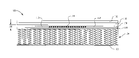
[0009] FIG. 1 illustrates a cross sectional side view of a
mattress assembly in
accordance with one or more embodiments of the present disclosure;
[0010] FIG. 2 illustrates a top down view of the mattress
assembly of FIG. 1
in accordance with one or more embodiments of the present disclosure;
[0011] FIG. 3 illustrates a cross sectional view of a hybrid
posture support
system in accordance with one or more embodiments of the present disclosure;
[0012] FIG. 4 illustrates a cross sectional side view of a
mattress assembly in
accordance with one or more embodiments of the present disclosure; and
3
CA 3042654 2019-05-07
[0013] FIG. 5 illustrates a cross sectional view of a hybrid
posture support
system in accordance with one or more other embodiments of the present
disclosure.
DETAILED DESCRIPTION
[0014] Disclosed herein are mattress assemblies including a hybrid
posture
support system that provide an end user with improved posture support during
use,
among other advantages. The mattress assemblies generally include the hybrid
posture support system overlying an innercore, wherein the hybrid posture
support
system includes a non-latex foam top layer including first and second foam
portions
embedded therein or adhesively attached thereto that are spaced apart and
generally
correspond to a head/shoulder region and a foot region, respectively, a
pocketed
microcoil array underlying the latex foam top layer that is intermediate the
first and
second foam portions, and an underlying foam layer. The hybrid posture support
system can be used in any mattress assembly including mattresses having a coil
spring
innercore or a foam innercore.
[0015] The mattress assemblies may be a mattress of any size,
including
standard sizes such as a twin, queen, oversized queen, king, or California
king sized
mattress, as well as custom or non-standard sizes constructed to accommodate a
particular user or a particular room. The mattress assemblies are generally
rectangularly shaped and configured as one sided mattresses. Advantageously,
mattress assemblies including the hybrid posture support system as generally
described above provides an occupant thereon with proper spinal alignment and
also
provides pressure relief. Moreover, the presence of the pocketed microcoil
array
when used in combination with a coil spring innercore provides increased air
flow.
[0016] Turning now to FIGS. 1-3, there is depicted a mattress
assembly 100
including a plurality of layers. The mattress assembly 100 has a coil spring
innercore
104 of a standard coil height within a range of about 4 to about 10 inches
disposed on
a foam layer 102. A hybrid posture support system 106 overlies the coil spring
innercore 104, wherein the hybrid support system 106 includes a foam top layer
108
including first and second foam portions 110, 112, respectively, embedded
therein or
4
CA 3042654 2019-05-07
attached thereto that are spaced part and generally correspond to a
head/shoulder
region and a foot region of the mattress assembly, a pocketed microcoil array
114
underlying the foam top layer 108 intermediate the first and second foam
portions
110, 112, and an underlying foam layer 116 overlaying the innercore 104. In
one or
more embodiments, the vertical position of the hybrid posture support system
106 is
not intended to be limited so long as it overlays the coil spring innercore
104. In one
or more embodiments, the hybrid support system 106 can be in direct contact
with the
coil spring innercore 104. The illustrated mattress assembly 100 can further
include
one or more optional foam layers overlying and/or underlying the hybrid
posture
support system 106, two of which are shown overlaying the hybrid posture
support
system 106 as indicated by reference numerals 118 and 120.
[0017] As shown in the top down view of FIG. 2, the microcoil
array 114 as
well as the first and second foam portions 110, 112, respectively, spans the
width (W)
and a portion of the length (L) of the mattress assembly 100, wherein the
microcoil
array 114 is centrally located along the length (L). Likewise, the first and
second
foam portions 110, 112 span the width (W) and a portion of the length (L) of
the
mattress assembly 100. As shown more clearly in FIG. 3, the pocketed microcoil
array 114 is intermediate to the first and second foam portions 110, 112 and
abuts the
first and second foam portions. The first foam 110 is proximate to the head
end 130
of the mattress assembly and the second latex foam portion 112 is proximate to
the
foot end 140 of the mattress assembly 100.
[00181 In one or more embodiments, the pocketed microcoil array
114 can
have a length from about 6 inches to about 60 inches. In one or more other
embodiments, the microcoil array 114 can have a length of about 12 to about
36, and
in still one or more other embodiments, the microcoil array 114 can have a
length of
about 18 to about 28 inches, which is positioned to generally correspond to
the
lumbar portion of a mattress.
[0019] The first and second foam portions 110, 112, can have the
same
lengths or different lengths. In one or more embodiments, the first and second
foam
portions 110, 112, can have lengths of about 4 inches to about 24 inches. In
one or
CA 3042654 2019-05-07
more other embodiments, the first and second foam portions 110, 112, can have
lengths of about 6 inches to about 18 inches, and in still one or more
embodiments,
the first and second foam portions 110, 112, can have lengths of about 8
inches to
about 12 inches. The thickness of the first and second portions 110, 112,
respectively,
can be within a range about 0.3 inches to about 3 inches. As noted above, the
first
and second foam portions generally correspond to the head/shoulder region and
the
foot/leg region and abut each end of the pocketed microcoil array 114.
[0020] The first and second foam portions are not intended to be
limited to
any particular foam. However, generally, the first and second foam portions
have
different properties and/or are formed of different materials than top foam
layer 108
and underlying foam layer 116. By way of example, the first and second foam
portions can be a synthetic or natural latex foam, a viscoelastic foam, a gel
infused
foam, or the like.
100211 By way of example, for a typical standard queen-sized or
king-sized
mattress, the length dimension is about 80 inches. The microcoil array 114 and
the
adjacent first and second portions 110, 112, respectively are centrally
located along a
length of the non-latex foam layer and spans the width dimension from one side
of the
mattress assembly to the other side of the mattress assembly. The length of
the
microcoils array 114 can be about 24 inches and the lengths of the first and
second
foam portions can be about 10 inches. Underlying foam layer 116 and the top
foam
layer 108 sandwich the pocketed microcoil array 114 and the first and second
foam
portions 110, 112 to complete the hybrid posture support system 106.
[0022] The top foam layer 108 and the underlying foam layer 116
can have
the same or different thicknesses. In one or more embodiments, the thickness
of these
layers 108, 116 is in a range from about 0.5 inches to about 3 inches.
Moreover, the
top foam layer 108, the underlying foam layer 116 and the optional upper
layers that
overlay or underlie the hybrid posture support system 106 are not intended to
be
limited to any particular foam. Suitable other foam layers include, without
limitation,
polyurethane, viscoelastic polyurethane, polyethylene, polypropylene, a gel
infused
foam, and the like. Additionally, one of more of the foam layers can be
perforated or
6
CA 3042654 2019-05-07
have convoluted surfaces, can include phase change materials, thermally
conductive
materials, or the like. Moreover, with respect to the underlying foam layer
116 and
optional layers overlying and underlying the hybrid posture support system
106,
synthetic and natural latex can be used. Optionally, in some embodiments, one
or
more of the foam layers including the foam portions 110, 112 may be pre-
stressed
such as is disclosed in US Pat. Pub. No. 2010/0072676, incorporated herein by
reference in its entirety.
[0023] The various foams suitable for use in the foam layer may be
produced
according to methods known to persons ordinarily skilled in the art. For
example,
polyurethane foams are typically prepared by reacting a polyol with a
polyisocyanate
in the presence of a catalyst, a blowing agent, one or more foam stabilizers
or
surfactants and other foaming aids. The gas generated during polymerization
causes
foaming of the reaction mixture to form a cellular or foam structure. Latex
foams are
typically manufactured by the well-known Dunlap or Talalay processes.
[0024] The different properties of the foam layers 108, 116, the
first and
second foam portions 110, 112 of the hybrid posture support system 106, as
well as
the optional foam layers overlying and/or underlying the hybrid posture
support
system 106, e.g., layers 102, 118, 120, may include, but are not limited to,
density,
hardness, thickness, support factor, flex fatigue, air flow, various
combinations
thereof, and the like. Density is a measurement of the mass per unit volume
and is
commonly expressed in pounds per cubic foot. The hardness properties of foam
are
also referred to as the indention load deflection (ILD) or indention force
deflection
(IFD) and is measured in accordance with ASTM D-3574. Like the density
property,
the hardness properties can be varied in a similar manner. Moreover,
combinations of
properties may be varied for each individual layer. The individual layers can
also be
of the same thickness or may have different thicknesses as may be desired to
provide
different tactile responses.
[0025] The hardness for the different foam layers generally have
an indention
load deflection (ILD) of 7 to 30 pounds force for viscoelastic foams and an
ILD of 7
to 45 pounds force for non-viscoelastic foams. The density of the different
foam
7
CA 3042654 2019-05-07
layers 108, 116, and the first and second foam portions 110, 112 can generally
range
from about 1 to 2.5 pounds per cubic foot for non-viscoelastic foams and 1.5
to 6
pounds per cubic foot for viscoelastic foams. In one or more embodiments, the
first
and second foam portions 110, 112, respectively, have a hardness and a density
greater than the top layer 108 and the underlying layer 116.
[0026] The microcoil array 114 includes a plurality of coils
contained in
separate pockets formed of a piece of fabric disposed between or surrounds
each
microcoil in the microcoil cell, i.e., pocketed coils. As used herein, a
microcoil is a
spring or coil that has a smaller height and diameter than conventional
innersprings
used in mattresses such as that used in a coil innercore. Suitable dimensions
for each
microcoil include, but are not limited to, a diameter and height of less than
about 4
inches. In one or more embodiments, the diameter of less than about 3 inches
and in
still one or more other embodiments, a diameter of less than about 2 inches.
In one or
more embodiments, the height of less than about 3 inches and in still one or
more
other embodiments, a height of less than about 2 inches. The microcoils can be
pre-
compressed or uncompressed within the pocket. In addition, the microcoil is
generally constructed from a thinner or more flexible gauge of wire. In one or
more
embodiments, the gauge of the wire is greater than about 14 gauge. In another
embodiment, the gauge of the wire is at least about 19 gauge. While
illustrated as a
cylindrical shaped coil with a generally circular cross section, each
microcoil can
have other shapes including barrel shaped, hour glass shaped or cone shaped
and can
have other cross-sectional shapes including oblong and rectangular.
[0027] As shown, the microcoil array 114 is in the form of a grid
including
rows and columns of pocketed microcoils. The microcoil array 114 as well as
the
first and second foam portions 110, 112 can be adhesively secured to a
selected one or
both of the top foam layer 108 and the underlying foam layer 116.
[0028] In contrast to the microcoils, the coils in the innercore
coil spring layer
104 can have a coil gauge is about 12 to about 16 and the density of coils
within a
mattress generally ranges from about 400 to about 2,000. The standard size
generally
ranges from about 4 inches to about 12 inches. Typically, the standard height
is about
8
CA 3042654 2019-05-07
8 inches. For many years, one form of spring assembly construction has been
known
as Marshall Construction. In Marshall Construction, individual wire coils are
each
encapsulated in fabric pockets and attached together in strings which are
arranged to
form a closely packed array of coils in the general size of the mattress.
Examples of
such construction are disclosed in U.S. Pat. No. 685,160, U.S. Pat. No.
4,234,983,
U.S. Pat. No. 4,234,984, U.S. Pat. No. 4,439,977, U.S. Pat. No. 4,451,946,
U.S. Pat.
No. 4,523,344, U.S. Pat. No. 4,578,834, U.S. Pat. No. 5,016,305 and U.S. Pat.
No.
5,621,935, the disclosures of which are incorporated herein by reference in
their
entireties.
[0029] The coil springs are not intended to be limited to any
specific type or
shape. The coil springs can be single stranded or multi-stranded, pocketed or
not
pocketed, asymmetric or symmetric, and the like. It will be appreciated that
the
pocket coils may be manufactured in single pocket coils or strings of pocket
coils,
either of which may be suitably employed with the mattresses described herein.
The
attachment between coil springs may be any suitable attachment. For example,
pocket
coils are commonly attached to one another using hot-melt adhesive applied to
abutting surfaces during construction.
[0030] The proposed coil spring construction for use in the
mattress assembly
can employ a stranded wire spring which is made of at least 2 wire strands
that are
twisted to form a multi-wire cord. The number of strands employed will vary
according to the application and may vary based on the type of material used
to form
the strand. Thus, the wire may include two or more strands, and can include
from
three to fifty strands.
[0031] The strands may be twisted, weaved, clipped or bonded
together and
any suitable method for forming the stranded wire spring may be employed
without
departing from the scope of the invention. The strands may be steel, aluminum,
plastic, copper, titanium, rubber or any other suitable material and the type
of material
selected will depend upon the application at hand. Moreover, the strands may
have
any suitable shape and may be long cylindrical wires, hexagonal wire, square
wire or
any other shape or geometry. Additionally, the wire strand gauge may vary
according
9
CA 3042654 2019-05-07
to the application and in one embodiment comprises 710 gauge wire, although
other
gauges may be used.
[0032] In one practice, coiling may be achieved construction by
passing a
braided strand through a coiler, such as the type of coiler employed for
forming steel
mattress coils wherein a heavy-gauge steel wire is compressed into a barrel-
shaped
coil such that no turns touch for eliminating noise and vibration. The coils
may then
be passed to a pocketing machine or station to pocket the springs into
individual
sleeves of a non-woven, non-allergenic fabric such as Duon. Each sleeve may be
ultrasonically sealed, a process where the fibers are melted together to form
solid
plastic seams that are secure and tear-resistant. The coils are then fusion
bonded to
produce a strong, stable construction. The number of coils in each unit may
vary, and
the types of coils and the number of strands and gauge of strands can vary
from
pocket to pocket.
[0033] The individual strands are connected with each other at
least at the
ends of the coil. Since the strands can rub against each other over the length
of the
coil, which can cause fretting and premature wear, the strands may be coated
and/or
pre-galvanized. Moreover, the stranded coil may also be sealed with a sealant,
such as
an epoxy. Thus, in alternative and optional embodiments, the strands may be
coated
or otherwise treated and the wire may be sealed or coated. Exemplary stranded
wire
for use in mattresses is disclosed in US Pat. No. 7,047,581, US Pat. No.
7,168,117,
and US Pat. No. 8,099,811 incorporated herein by reference in its entireties.
[0034] Referring now to FIG. 4, there is depicted a mattress
assembly 200
including the hybrid posture support system 106 as discussed above overlying a
foam
innercore 204. The mattress assembly 200 can include optional foam layers,
e.g.,
118, 120 overlaying the hybrid posture support system 106, foam layers, e.g.,
102,
underlying the foam innercore 2014, and foam layers (not shown) intermediate
the
hybrid support system 106 and the innercore 204.
CA 3042654 2019-05-07
[0035] The foam, in some embodiments, can be a monolithic block of a single
type of resilient foam selected from foams having a range of densities
(themselves
well-known in the art) or multiple foam layers for supporting one or more
occupants
during sleep. In one or more embodiments, the foam within the innercore unit
is made
of any industry-standard natural and/or synthetic foams, such as (but not
limited to)
latex, polyurethane, or other foam products commonly known and used in the
bedding
and seating arts having a density of 1.5 to 1.9 lb/ft3 and 20 to 35 pounds-
force ILD.
Although a specific foam composition is described, those skilled in the art
will realize
that foam compositions other than one having this specific density and ILD can
be
used. For example, foams of various types, densities, and ILDs may be
desirable in
order to provide a range of comfort parameters to the buyer.
[0036] The foam innercore unit 204 may comprise one or more
horizontal
layers of multiple types of foams arranged in a sandwich arrangement. This
sandwich
of different foams, laminated together, may be substituted for a homogeneous
foam
block of a single density and/or ILD.
[0037] In a further embodiment, the foam innercore 204 may
comprise one or
more vertical regions of different foam compositions (including vertical
regions
having multiple horizontal layers), where the different foams are arranged to
provide
different amounts of support (also referred to as "firmness" in the art) in
different
regions of the sleeping surface.
[0038] Optionally, the mattress assembly can further include a
foam side rail
assembly about all or a portion of the perimeter of the mattress layers
including the
foam or coil spring innercore. In one or more embodiments, the side rail
assembly
can be formed on the bottom most layer so as to define a bucket assembly. The
side
rails that define the assembly may be attached or placed adjacent to at least
a portion
of the perimeter of the mattress layers and may include metal springs, spring
coils,
encased spring coils, foam, latex, gel, viscoelastic gel, or a combination, in
one or
more layers. Side rails may be placed on opposing sides of the stacked
mattress
layers, on all four sides of the stacked mattress layers, or only on one side
of the
stacked mattress layers. In certain embodiments, the side rails may comprise
edge
11
CA 3042654 2019-05-07
supports with firmness greater than that provided by the stacked mattress
layers. The
side rails may be fastened to the stacked mattress layers via adhesives,
thermal
bonding, or mechanical fasteners.
[0039] In one or more embodiments, the side rail assembly can be
formed of
open cell polyurethane foam having a non-random large cell structure or a
random
cellular structure with many large cells. The large cell structure can be
defined by the
number of cells per linear inch. In one embodiment, the large cell structure
is about
to 40 cells per inch, with about 15 to 30 cells per inch in other embodiments,
and
with about 20 cells per inch in still other embodiments. The open cell foam
structure
includes a plurality of interconnected cells, wherein the windows between the
adjacent cells are broken and/or removed. In contrast, in a closed cell foam
there are
substantially no interconnected cells and the windows between the adjacent
cells are
substantially intact. In reticulated foams, substantially all of the windows
are
removed. By using an open cell structure with a large open cellular structure,
movement of moisture and air through a side rail can occur. Also, if the side
rail is
adhesively or thermally attached to the mattress layers, e.g., 102, 104, and
106, the
skeletal struts of the open cell foam will bond to the mattress layers,
thereby
facilitating air and moisture transfer from the mattress layers through the
side layers
to the environment. In one or more embodiments, the side rail assembly
includes a
reticulated viscoelastic polyurethane foam.
[0040] For ease in manufacturing the mattress assembly, the side
rail
assembly may be assembled in linear sections that are joined to one another to
form
the perimeter about the mattress layers. The respective ends may be square or
may be
mitered.
[0041] Other layers may include any materials suitable for a
mattress, such as
batting, foam, waterproof liners, and so forth. In certain assemblies using
coils, the
one or more additional layers may include a relatively firm bottom panel layer
that
distributes the upward force of each spring top to provide a more uniform feel
to the
sleeping surface.
12
CA 3042654 2019-05-07
[0042] Referring now to FIG. 5, there is depicted a hybrid posture
support
system 300 that can be used in the above described coil spring inner core or
foam
innercore mattress assemblies in accordance with one or more embodiments of
the
present invention. The hybrid posture support system 300 includes a top foam
layer
302 and an underlying foam layer 304. Intermediate the top and underlying foam
layers 302, 304, respectively, are first and second microcoil array portions
310, 312
embedded therein or attached to a selected one or both of the top foam layer
302 and
the underlying foam layer 304. The first and second microcoil array portions
320,
322, respectively, are spaced part and generally correspond to a head/shoulder
region
and a foot region of the mattress assembly. A foam portion 324 is intermediate
and
abuts the first and second microcoil array portions 310, 312. The foam portion
324
and the microcoil array portions 320, 322 are centrally located along a length
of the
mattress as previously described and generally corresponds to the lumbar
region of a
mattress. In contrast, the first and second microcoil array portions 310, 312
generally
correspond to the head region and the foot leg regions.
[0043] Referring In one or more embodiments, the foam portion 324
can have
a length from about 6 inches to about 60 inches. In one or more other
embodiments,
the foam portion 324 can have a length of about 12 to about 36, and in still
one or
more other embodiments, the foam portion 324 can have a length of about 18 to
about
28 inches, which is positioned to generally correspond to the lumbar portion
of a
mattress.
[0044] The first and second foam portions 110, 112, can have the
same
lengths or different lengths. In one or more embodiments, the first and second
microcoil array portions 310, 312 can have lengths of about 4 inches to about
24
inches. In one or more other embodiments, the first and second microcoil array
portions 310, 312 can have lengths of about 6 inches to about 18 inches, and
in still
one or more embodiments, the first and second microcoil array portions 310,
312 can
have lengths of about 8 inches to about 12 inches. As noted above, the first
and
second microcoil array portions 310, 312 generally correspond to the
head/shoulder
region and the foot/leg region and abut each end of the foam portion 324.
13
CA 3042654 2019-05-07
[0045] In still one or more other embodiments, the hybrid posture
support
system can include one or more air bladders in place of a selected one of the
adjacent
portions or the centrally located portion. For example, air bladders can be
used in
place of first and second foam portions 110, 112 or can be used in place of
the
pocketed microcoil array 114 in mattress assemblies 100, 200.
[0046] The mattress assemblies, and any variations thereof, may
be
manufactured using techniques known in the art of mattress making, with
variations
to achieve the mattress described above. Likewise, the various mattress layers
in the
mattress assemblies described above may be adjoined to one another using an
adhesive or may be thermally bonded to one another or may be mechanically
fastened
to one using known in the art.
[0047] This written description uses examples to disclose the
invention,
including the best mode, and also to enable any person skilled in the art to
make and
use the invention. The patentable scope of the invention is defined by the
claims, and
may include other examples that occur to those skilled in the art. Such other
examples are intended to be within the scope of the claims if they have
structural
elements that do not differ from the literal language of the claims, or if
they include
equivalent structural elements with insubstantial differences from the literal
languages
of the claims.
14
CA 3042654 2019-05-07