Note: Descriptions are shown in the official language in which they were submitted.
CA 03042863 2019-05-03
WO 2018/085506
PCT/US2017/059670
DECONTAMINATION SYSTEM USING FORCED AIR AND METHODS OF USING
THE SAME
CROSS REFERENCE TO RELATED APPLICATIONS
(0001] This application claims priority to U.S. Provisional Patent
Application Serial
No. 62/418,512 filed November 7, 2016. This application is incorporated herein
by reference,
in its entirety.
TECHNICAL FIELD
[0002] The present disclosure relates to decontamination of devices, such
as medical
devices. More particularly, the present disclosure relates to systems and
methods for
decontaminating medical devices having a lumen.
BACKGROUND
[0003] Advanced medical instruments formed of rubber and plastic
components with
adhesives are delicate and often unsuited to the high temperatures and
pressures associated
with a conventional steam autoclave. Steam autoclaves often operate under
pressure cycling
programs to increase the rate of steam penetration into the medical devices or
associated
packages of medical devices undergoing sterilization. Steam sterilization
using gravity, high
pressure, or pre-vacuum, creates an environment where rapid changes in
temperature or
pressure can take place. Complex instruments which are often formed and
assembled with
very precise dimensions, close assembly tolerances, and sensitive optical
components, such as
endoscopes, may be destroyed or have their useful lives severely curtailed by
harsh
sterilization methods employing high temperatures and high or low pressures.
[0004] Endoscopes can present certain problems in that such devices
typically have
numerous exterior crevices and interior lumens which can harbor microbes.
Microbes can be
found on surfaces in such crevices and interior lumens as well as on exterior
surfaces of the
endoscope. Other medical or dental instruments which comprise lumens,
crevices, and the
like can also provide challenges for decontaminating various internal and
external surfaces
that can harbor microbes. There is thus a need for a decontamination system or
process that
CA 03042863 2019-05-03
WO 2018/085506
PCT/US2017/059670
can be used to adequately decontaminate a device having a lumen without
risking damage to
the device.
SUMMARY
(0005] Disclosed herein is a system for decontaminating a device. The
system
comprises a chamber defming an enclosed space. The chamber is configured to
withstand
pressure changes within the enclosed space and receive a device that includes
a lumen. The
system further includes a controller configured to control a temperature and
pressure within
the chamber, a vacuum pump in fluid communication with the enclosed space, and
a source of
a decontaminating substance. The system further includes at least one of a
vaporizer or
atomizer in fluid communication with the source of decontaminating substance
and
configured to provide a vaporized decontaminating substance within the
enclosed space, and a
pump positioned within the chamber. The pump has an inlet and an outlet
wherein one of the
inlet and outlet is in fluid communication with the enclosed space of the
chamber and the
other of the inlet and the outlet is configured to be in fluid communication
with the lumen.
[0008] Also disclosed herein is a system for decontaminating a device
having a lumen.
The system comprises a decontamination chamber defining an enclosed space. The
decontamination chamber is configured to withstand pressure changes within the
enclosed
space. The system further includes a container positioned within the enclosed
space. The
container has an outer wall that is permeable by a vaporized decontaminating
substance. The
system further includes a device having a lumen, the device may be positioned
within the
container; a controller for controlling a temperature and pressure within the
decontamination
chamber; a vacuum pump in fluid communication with the enclosed space; and a
source of a
decontaminating substance. The system further includes at least one of a
vaporizer or
atomizer for vaporizing the decontaminating substance, the vaporizer or
atomizer in fluid
communication with the source of the decontaminating substance and the
enclosed space. The
system further includes a pump positioned within the decontamination chamber,
the pump
having a first opening in fluid communication with the enclosed space and a
second opening
in fluid communication with the lumen.
[0007] Also disclosed herein is a method of decontaminating a device
containing a
lumen. The method comprises placing the device inside a container and placing
the container
2
CA 03042863 2019-05-03
WO 2018/085506
PCT/US2017/059670
within a decontamination chamber defining an enclosed space. The method
further includes
decreasing the pressure inside the enclosed space to a pressure below
atmospheric pressure,
directing a vaporized decontaminating substance into the enclosed space, and
providing a
flow of air containing the vaporized or atomized decontaminating substance
from the
enclosed space into a lumen of the device with a pump located within the
enclosed space or
the container.
[0008] While multiple embodiments are disclosed, still other embodiments
of the
present invention will become apparent to those skilled in the art from the
following detailed
description, which shows and describes illustrative embodiments of the
invention.
Accordingly, the drawings and detailed description are to be regarded as
illustrative in nature
and not restrictive.
BRIEF DESCRIPTION OF THE DRAWINGS
[0009] FIG. 1 is a schematic view of a decontamination system according to
some
embodiments.
[0010] FIG. 2 is a graph showing pressure versus time in an exemplary
decontamination cycle.
[0011] FIG. 3 is a schematic view of a decontamination system according to
some
embodiments.
[0012] FIG. 4 is a schematic view of a decontamination system according to
some
embodiments.
[0013] FIG. 5 is a schematic view of a decontamination system according to
some
embodiments.
[0014] FIG. 6 is a schematic view of a decontamination system according to
some
embodiments.
[0015] FIG. 7 is a schematic view of a decontamination system for a
multilumen
device.
[0016] FIG. 8 is a schematic view of an alternative decontamination system
for a
multilumen device.
3
CA 03042863 2019-05-03
WO 2018/085506
PCT/US2017/059670
DETAILED DESCRIPTION
[0017] Devices, such as medical devices, can be decontaminated or
sterilized at
relatively low temperatures using hydrogen peroxide (H202) and/or peracetic
acid (PAA)
chemistry. In such systems, the chemistry may be provided as a vapor into a
decontamination
chamber containing the device to be decontaminated. The surfaces of the device
will be
decontaminated when contacted with the chemistry. Lumen devices may be
particularly
challenging to decontaminate as there must be flow of the decontaminating
substance through
the lumen. The instant disclosure describes a decontamination system which
provides
sufficient flow of the decontaminating substance through a lumen device to
achieve
decontamination of the lumen device. A method of using is also described.
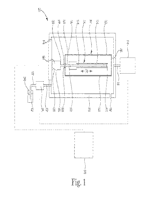
[0018] FIG. 1 is a schematic view of a decontamination system 10 which
includes a
decontamination chamber 20, a vacuum pump 32, a vaporizer 34, a source of
decontaminating
substance 36 maintained in a package 42, a controller 38, a vent 48, a pump
80, and a device
50 positioned within a container 60. Vacuum pump 32 is connected to
decontamination
chamber 20 by conduit 44. Vaporizer 34 is connected to decontamination chamber
20 by
conduit 40. Decontaminating substance 36 is maintained in package 42 and is
connected to
vaporizer 34 by conduit 46. Controller 38 is connected to the vacuum pump 32,
vaporizer 34,
and pump 80 and is configured to control these items. In some embodiments,
controller 38 is
connected to one or more of the decontamination chamber 20, vacuum pump 32,
vaporizer 34,
packaging 42 and pump 80.
[0019] Decontamination chamber 20 defines an enclosed space. The
decontamination
chamber 20 includes a door 30 that is configured to accommodate inserting or
removing the
container 60. The decontamination chamber 20 is configured to withstand
pressure changes
within the decontamination chamber 20 as described herein. The door 30 may be
sealed
and/or reinforced to provide a sealed environment within the decontamination
chamber 20
that is higher or lower than the pressure outside the decontamination chamber
20.
[0020] The vacuum pump 32 is connected to the decontamination chamber 20
and is
configured to change the pressure within the decontamination chamber 20. For
example, the
vacuum pump 32 may be configured to withdraw gas from the decontamination
chamber 20
to lower the pressure inside the decontamination chamber 20. The vacuum pump
32 may
4
CA 03042863 2019-05-03
WO 2018/085506
PCT/US2017/059670
also be configured to add gas into the decontamination chamber 20 to increase
the pressure
inside the decontamination chamber 20.
[0021] In some embodiments, the decontamination chamber 20 may also
include the
vent 48 to adjust the pressure within the decontamination chamber. For
example, the vent 48
may be controlled by controller 38 to be in a partially or fully open position
or in a closed
position. In some embodiments, the vent 48 may be in a closed position when
the vacuum
pump 32 is adjusting the pressure inside the decontamination chamber 20 above
or below
atmospheric pressure and may be in a partially or fully open position when the
vacuum pump
32 is adjusting the pressure inside the decontamination chamber 20 atmospheric
pressure. For
example, the vent 48 may be in a partially or fully open position such that
atmospheric air can
enter the decontamination chamber 20 when the vacuum pump 32 is drawing air
from the
decontamination chamber 20 to flush air through the decontamination chamber
20.
[0022] The package 42 containing the decontaminating substance 36 and the
vaporizer
34 are located outside the decontamination chamber 20. The package 42 is
connected to the
vaporizer 34 by conduit 46 and the vaporizer 34 is connected to the
decontamination chamber
20 by conduit 40. Together conduits 46 and 40 provide a fluid connection from
the package
42 into the decontamination chamber 20 such that the decontaminating substance
36 flows
from the packaging 42 through the vaporizer 34 into the decontamination
chamber 20.
[0023] The decontaminating substance 36 may include chemistry suitable for
use in a
sterilization process. For example, the decontaminating substance 36 may
include a chemical
or other substance that complies with the International Organization for
Standardization (ISO)
standard ISO/TC 198, Sterilization of Healthcare Products and/or the
Association for the
Advancement of Medical Instrumentation (AAMI) standard ANSI/AAMI/ISO 11140-
1:2005,
"Sterilization of Healthcare Products ¨ Chemical Indicators ¨ Part I: General
Requirements"
(Arlington, VA: AAMI 2005). In some embodiments, suitable decontaminating
substance 36
includes chemistry that can be dispersed as a fluid, such as a liquid, a
vapor, or a combination
thereof (such as a fog) during the decontamination process. For example,
suitable
decontamination substances may include hydrogen peroxide (H202) and/or
peracetic acid
(PAA). Decontaminating substance 36 may be kept at room temperature (e.g., 20
C to 30 C)
CA 03042863 2019-05-03
WO 2018/085506
PCT/US2017/059670
before being provided to the vaporizer 34. Decontaminating substance 36 may be
refrigerated
or heated before being provided to the vaporizer 34.
[0024] The vaporizer 34 converts the decontaminating substance 36 into a
vapor, fog
or other suitable form for the decontamination process. For example, in some
embodiments
the vaporizer 34 may heat the decontaminating substance 36 provided in a
liquid form to
vaporize or otherwise transform the liquid decontaminating substance 36 into a
vapor or gas.
In some embodiments, the vaporizer 34 may convert the decontaminating
substance 36 into a
vapor or fog via a mechanical means such as an atomizing nozzle or a sprayer.
For example,
the vaporizer may include an atomizer that uses a mechanical force such as
rotating blades or
air pressure to break up a stream of liquid decontaminating substance 36 into
individual
droplets and/or to produce an aerosol. The droplets or aerosol of
decontaminating substance
36 may be released into the decontamination chamber 20 where they may
evaporate into the
gas phase to form a vapor. In some embodiments, the decontaminating substance
36 may be
pulled into the vaporizer 34. In other embodiments, the decontaminating
substance 36 may be
pushed into the vaporizer 34.
[0025] The controller 38 provides control signals to and/or receives
condition sensing
and equipment status signals from other elements of the decontamination system
10. For
example the controller 38 may include monitoring and control of the vaporizer
34, the
vacuum pump 32, and the pump 80. The controller 38 may regulate delivery of
the
decontaminating substance 36 to the vaporizer 34. The controller 38 may adjust
the
environmental conditions within the decontamination chamber 20. The controller
38 may
provide control signals to and/or receive condition sensing and equipment
status signals from
the vacuum pump 32 for adjustment of the pressure of the decontamination
chamber 20.
[0026] The decontamination chamber 20 is configured to receive the device
50 within
a container 60. The device 50 may include one or more lumens 52 having a first
end 70, a
second end 72 and a length 74. The lumen 52 extends the length of the device
50, and has an
inner diameter that is smaller than the length 74 of the lumen. For example,
the device 50
may be a medical device, such as an endoscope, having a rigid or flexible
lumen that extends
the length of the device. In some embodiments, an endoscope lumen may have a
length
several times larger than the inner diameter. For example, an endoscope lumen
may have an
6
CA 03042863 2019-05-03
WO 2018/085506
PCT/US2017/059670
inner diameter of about l to 4 millimeters (mm) and may have a length of about
I to 3 meters
(m).
[0027] In some
embodiments, the decontamination chamber 20 may be operated at
room temperature (e.g., 20 C to 30 C), below room temperature, or above room
temperature.
For example, in some embodiments, the decontamination chamber 20 may include a
heater or
other device for increasing the temperature of the decontamination chamber 20.
In some
embodiments, the decontaminating substance 36 can be heated to a vapor and the
vapor may
heat the decontamination chamber 20 to a temperature above room temperature
(e.g., above
20 C or 30 C).
[0028] The
container 60 forms an enclosed space and holds one or more devices 50.
The container 60 may have one or more sides or portions 64 that forms the
enclosed space.
Sides or portions 64 may be flexible or rigid. The sides or portions 64 of
container 60 may be
of the same material or different materials. For example, the container 60 may
be a flexible
pouch made entirely or partially from one or more pliable or flexible portions
64. In another
example, the container 60 may be a case or other enclosure formed from a rigid
material. In a
further example, container 60 may have a rigid bottom 62 and portions 64 and
may have a
flexible top 66 or lid. In some embodiments, the container 60 may be
disposable. In other
embodiments, the container 60 may be reusable. The container 60 may be
designed to contain
the device 50 during a decontamination process, and maintain the device 50 in
a sterile
condition after the device 50 is removed from the decontamination chamber 20.
[0029] The
container 60 may have at least a section of a surface 76 through which the
decontaminating substance 36 may penetrate or permeate. For example, vaporized
decontaminating substance 36 in the decontamination chamber 20 may contact and
decontaminate the outer surface 76 of the container 60. The vaporized
decontaminating
substance 36 in the decontamination chamber 20 may also permeate through the
outer surface
76 of the container 60, enter the container 60, and decontaminate at least the
outer surface 54
of the device 50.
[0030] The pump
80 is connected to the lumen 52 of the device 50 and is positioned
within the decontamination chamber 20 and outside of the container 60. In some
embodiments, the pump 80 may be attached to an inside surface of the
decontamination
7
CA 03042863 2019-05-03
WO 2018/085506
PCT/US2017/059670
chamber 20. The pump 80 is configured to provide a sufficient flow rate so
that the fluid from
decontamination chamber 20 flows the entire length 74 of the lumen 52.The pump
80 may be
any suitable device for moving air or for inducing material flow. For example,
the pump 80
may be an air pump, a fan, a compressor, a blower, or bellows
[0031] The pump 80 has an inlet 96 and an outlet 98. Fluid enters the pump
80
through the inlet 96 and exits the pump 80 through the outlet 98. The inlet 96
is exposed to,
or is in fluid communication with, the environment within the decontamination
chamber 20.
In some embodiments, the decontamination system 10 provides fluid
communication from the
pump 80 to the device 50 to direct air flow from the pump to the device 50 and
the lumen 52.
For example, during a decontamination cycle, the pump 80 directs air
containing
decontaminating substance 36 into the lumen 52 of the device 50. In some
embodiments, the
outlet 98 may be spaced a distance from the lumen 52 and direct a portion of
the air flow
around the lumen 52 and a portion of the air flow through the lumen 52
[0032] In some embodiments, the pump 80 may be powered using a magnetic
coupling. For example, the pump 80 may be positioned on the inside surface of
a wall of the
decontamination climber 20 and may be powered using a magnetic coupling to
turn the
pump 80 using a power source or mechanical force driving the pump 80 from
outside the
decontamination chamber 20. Additionally or alternatively, the pump 80 may be
battery
powered. In some embodiments, the pump 80 may be configured to turn on while
door 30 is
open. Additionally or alternatively, the pump 80 may be configured to turn on
when the door
30 is in the closed position. For example, controller 38 may turn on pump 80
when the door
30 is in the closed position.
[0033] In some embodiments, the system 10 may include a sensor 58 for
detecting the
air pressure inside the decontamination chamber 20. When a suitable air
pressure inside the
decontamination chamber 20 is detected, the pump 80 may be turned on by
controller 38, for
example.
[0034] In some embodiments, the pump 80 is in fluid communication with
device 50
and pump 80 forces air into lumen 52 of device 50. In some embodiments, the
pump 80 may
be in fluid communication with the device 50 via a conduit 78 that is attached
to the pump
outlet 98. The conduit 78 may be used to direct a flow of air from the pump 80
to any
8
CA 03042863 2019-05-03
WO 2018/085506
PCT/US2017/059670
suitable location such as the device 50 and/or the lumen 52. The conduit 78
may be attached
to the device 50 directly or via an additional connection. For example, the
conduit 78 may be
attached to a port 82 that provides fluid communication from the conduit 78 to
the device 50
inside the container 60. In some embodiments, the device 50 may not be
contained within a
container 60, and the device 50 may be directly connected to the outlet 98 of
the pump 80 or
may be connected to the conduit 78 which is connected to the outlet 98 of the
pump 80.
[0035] In some embodiments, the device 50 may be in fluid communication
with the
outlet 98 of the pump 80 through a direct connection or through a series of
intermediate
connections. For example, the port 82 may be positioned on the container 60 to
direct flow
from the pump 80 through a side 64 or top 66 of the container 60 to lumen 52.
The port 82
may include a portion extending from the outside of the container 60 and a
portion extending
into the container 60. The port 82 may be used to connect the device 50 in
fluid
communication with the pump 80. In some embodiments, conduit 78 connects the
pump 80
to port 82, and the lumen 52 may be connected to the port 82. In some
embodiments, conduit
78 connects the pump 80 to port 82, and a conduit 84 connects port 82 to the
lumen 52. The
port 82 may include a permeable material across the port 82 that allows
vaporized
decontaminating substance 36 to permeate through. Suitable permeable materials
include, for
example, a nonwoven material such as that sold under the tradename Tyvek . The
permeable material across the port 82 allows a sterile environment to be
maintained within the
container 60 after the container 60 is removed from chamber 20. The port 82
may be attached
to conduit 78 using any suitable connection such as a threaded connection, a
snap connection
that clamps around the connection, or a quick connect that has a male internal
pipe that may
be inserted into a spring loaded female external pipe that may be removed by
retracting the
female pipe which releases the male connection. In some embodiments, pump 80
may be
directly connected to wall 92 without a port 82.
[0036] As shown in FIG. I, the pump 80 is connected to the device 50 at
the first end
70 of the lumen 52. In use, the pump 80 may push air that contains vaporized
decontaminating substance 36 into the first end 70 of the lumen 52. The pump
80 may also
pull air from the first end 70 of the lumen 52 which causes air containing
vaporized
decontaminating substance 36 to be drawn into the second end 72 of the lumen
52. Air in the
9
CA 03042863 2019-05-03
WO 2018/085506
PCT/US2017/059670
decontamination chamber 20 that contains vaporized decontaminating substance
36 may
permeate through the container 60 and be drawn into the second end 72 of the
lumen 52. In
some embodiments, the pump 80 may be designed to alternate between pushing and
pulling
air from inside the lumen 52. In this way, the pump 80 can provide flow in
either direction
along the length 74 of the lumen 52.
[0037] In some applications, it is challenging to achieve adequate
decontamination of
endoscopes due to the long, narrow lumens. Material transfer along the inside
of the length of
an endoscope is often difficult to achieve with passive diffusion of the
chemistry. For
example, an endoscope may have a lumen 52 with a length 74 of 1.0 meters, 2.0
meters, 3.0
meters or greater, and may have an internal diameter of 0.2 mm, 0.5 mm, 1.0
mm, 2.0 mm,
3.0 mm, or 4.0 mm. Systems utilizing passive diffusion of the chemistry down
the length of
the endoscope typically require long contact times and/or high chemistry
concentrations to
achieve adequate decontamination. Long processing times and/or high
concentrations
increase the risk of damaging the endoscope. Long processing times also lead
to operating
higher costs, as fewer devices can be decontaminated in a given amount of
time.
[0038] During a decontamination process, the pump 80 forces
decontaminating
substance 36 through lumen 52 and along the entire length 74 of the lumen 52.
For example,
pump 80 forces or directs air or other fluid containing decontaminating
substance 36 into the
lumen 52 at a suitable volumetric flow rate to travel the length 74 of the
lumen 52. In this
manner, the entire surface of the lumen 52 is contacted with decontaminating
substance 36.
[0039] In some embodiments, the pump 80 may provide a suitable volumetric
flow
rate to create a turbulent flow along the interior of the lumen 52. In other
embodiments, the
pump 80 may produce a laminar flow along the interior of lumen 52. The flow
rate of the
pump 80 may be adjusted based on the interior diameter of the lumen 52 to
provide the
suitable type of flow (i.e., laminar or turbulent).
[0040] The volumetric flow rate provided by the pump 80 may be
predetermined to
provide a specified amount of decontaminating substance 36 at a particular
rate. For example,
the concentration of vaporized decontaminating substance 36 in the air in the
decontamination
chamber 20 may be calculated, and the required volume of air that contains a
suitable amount
to
CA 03042863 2019-05-03
WO 2018/085506
PCT/US2017/059670
of decontaminating substance 36 may be forced through the lumen 52 in a
suitable amount of
time to achieve a required decontamination.
[0041] The decontamination system 10 with the pump 80 allows a user to
reduce the
risk of damage to the device to be decontaminated by reducing the time and the
chemistry
concentration needed to achieve sufficient or suitable decontamination. A
faster
decontamination process also allows a shorter decontamination process to be
used, which
increases the number of devices that can be processed with a single
decontamination system
during a given time period. Additionally, a lower concentration of the
decontaminating
substance 36 provides a decontaminating process that requires less
decontaminating substance
36 and less time to operate the decontamination system 10, thus decreasing the
cost of the
decontamination process.
(00421 The decontamination process is described below with reference to
the
decontamination system 10 described in FIG. 1, and the corresponding reference
numbers.
However, the decontamination process described herein may be carried out by
any of the
decontamination systems 10, 210, 310, 410 shown in FIGS. 1, 3, 4, 5, and 6. As
described
herein, a decontamination process includes at least one decontamination cycle,
in which a
decontamination cycle includes at least one release of decontaminating
substance 36 into the
decontamination chamber 20. In some embodiments, a decontamination process may
include
two or more identical decontamination cycles. The first step of a
decontamination cycle may
be decreasing the pressure within the decontamination chamber 20 below
atmospheric
pressure, and the last step may be returning the pressure within the
decontamination chamber
to atmospheric pressure. In some embodiments, a decontamination process begins
when
the device 50 is placed within the decontamination chamber 20, and ends when
the device 50
is removed from the decontamination chamber 20.
(0043] In some embodiments, to decontaminate the device 50 and lumen 52,
the
device 50 may be placed within the container 60 and the lumen 52 is attached
to the conduit
84. The device 50 may be sealed within the container 60 and placed in the
decontamination
chamber 20. The container 60 may be connected to the pump 80 by connecting the
conduit
84 to the port 82.
11
CA 03042863 2019-05-03
WO 2018/085506
PCT/US2017/059670
(0044] After
the device 50 is placed within decontamination chamber 20, the door 30
is closed and sealed. The pressure within the decontamination chamber 20 may
then be
decrease to below atmospheric pressure and decontaminating substance 36 may be
introduced
into the decontamination chamber 20. In some embodiments, the pressure may be
decreased
at the same time that decontaminating substance 36 is introduced.
Alternatively,
decontaminating substance 36 may be introduced after the pressure is reduced
in the chamber
20.
[0045] In some embodiments, the decontaminating substance 36 is introduced
into the
decontamination chamber 20 after being converted to a vapor or fog. For
example, a vapor
may be generated by delivering decontaminating substance 36 into the vaporizer
34 where the
decontaminating substance 36 is vaporized. The vaporized decontaminating
substance 36 is
then introduced into the decontamination chamber 20, under sub-ambient
pressure where it
fills the decontamination chamber 20. The decontaminating substance 36 may be
introduced
into the decontamination chamber 20 when the pressure of the decontamination
chamber 20 is
lower than atmospheric pressure, for example less than about 100 Torr, less
than about 50
Torr, or less than about 10 Torr.
[0046] In some embodiments, the decontaminating substance 36 may contain
about
59% hydrogen peroxide, and the balance water. In other embodiments, the
decontaminating
substance 36 may contain peracetic acid (PAA). For example, the
decontaminating substance
36 may include a chemistry that delivers PAA at a suitable concentration into
the
decontamination chamber 20. In some embodiments, suitable concentrations may
include a
weight percentage of PAA by weight of the decontaminating substance 36 from
about 1.0
wt.% to about 8.0 wt.%, from about 2.0 wt.% to about 7.0 wt.%, or from about
3.0 wt.% to
about 6.0 wt.%, or any weight percentage within these ranges.
(00471 In some embodiments, decontaminating substance 36 is provided in a
prerneasured volume sufficient to decontaminate the device 50 and the lumen
52. For
example, in some embodiments, a decontamination process includes transferring
a
predetemained amount of a decontaminating substance 36, such as aqueous
hydrogen
peroxide or peracetic acid (PAA), to the package 42. Additionally or
alternatively, the
decontaminating substance 36 may be provided in a large or bulk amount and
12
CA 03042863 2019-05-03
WO 2018/085506
PCT/US2017/059670
decontamination system 10 may provide a sufficient amount of decontaminating
substance 36
to vaporizer 34 for a particular decontamination cycle.
[0048] As described herein, at least a section of the outer surface 76 of
the container
60 containing device 50 is permeable to the vaporized decontaminating
substance 36. During
a decontamination cycle, the vaporized decontaminating substance 36 will
permeate through
the outer surface 76 of the container 60 and decontaminate the outer surface
54 of the device
50. The pump 80 forces air containing vaporized decontaminating substance 36
from
decontamination chamber 20 through the lumen 52 by either pushing or pulling
the air.
Forcing air through the lumen 52 increases the flow rate of air containing
decontaminating
substance 36 through the lumen 52. This increases the amount of chemistry to
which the
lumen 52 is exposed and decreases the cycle time and/or chemistry
concentration required to
achieve decontamination of the device 50 and the lumen 52.
E00491 The decontaminating substance 36 may be held in decontamination
chamber
20, and/or in lumen 52, for a period of time to facilitate decontamination of
the device 50.
When the decontaminating substance 36 has been held for a suitable amount of
time, the
controller 38 can vent the decontamination chamber 20 to a higher, but in some
embodiments,
still sub-atmospheric pressure. An air wash may be used to remove the vapor
containing the
decontaminating substance 36 from the decontamination chamber 20 and device
50. During
the air wash, the controller 38 may increase the pressure within the
decontamination chamber
20 and then decrease the pressure within the decontamination chamber 20. In
some
embodiments, the pump 80 may direct air into the device 50 to remove any
residual
decontaminating substance 36 in lumen 52. After the air wash, the inside of
the
decontamination chamber 20 can be returned to atmospheric pressure. While
multiple
embodiments for providing fluid flow through device 50, and specifically
through lumen 52,
are envisioned, in each embodiment, it is an object of the instant disclosure
to provide
sufficient decontaminating substance 36 along the length of the lumen 52 to
decontaminate
the lumen 52. In various embodiments, the instant application discloses a
system that enables
forcing air containing vaporized decontaminating substance 36 down the length
of the lumen
52.
13
CA 03042863 2019-05-03
WO 2018/085506
PCT/US2017/059670
[0050] FIG. 2 shows a graph of pressure versus time within decontamination
chamber
20 in an example embodiment of a decontamination cycle. As shown in FIG. 2,
the X-axis of
the graph illustrates time or duration, and the Y-Axis illustrates pressure
within the
decontamination chamber. As shown in FIG. 2, in some embodiments, a
decontamination
cycle may include multiple pressure changes within the decontamination
chamber. The
decontamination cycle or a portion of the decontamination cycle illustrated in
FIG. 2 may be
repeated several times within a decontamination process.
[0051] The decontamination cycle of FIG. 2 includes a vacuum
preconditioning step
610, a first decontamination step 620, and a second decontamination step 630.
The vacuum
preconditioning step 610 includes a first pump down 640 in which pressure is
drawn from the
decontamination chamber and an optional lumen warm up period 642. During the
lumen
warm up period 642, the pressure within the decontamination chamber is held
relatively
steady.
[0052] hi some embodiments, the vacuum preconditioning step 610 may be
followed
by the first decontamination step 620. During the first decontamination step
620,
decontaminating substance is injected into the decontamination chamber in a
first injection
step 650. During the first injection step 650 the pressure within the
decontamination chamber
increases. In an example embodiment, of decontaminating substance is injected
into the
decontamination chamber during the first injection step 650. The
decontaminating substance
may be injected into the decontamination chamber at a single injection at a
constant rate as
shown in the first injection step 650 or it may be injected in a plurality of
stepwise injections.
[0053] The first injection step 650 may be optionally followed by a
pressure increase
step 651. During the pressure increase step 651, the pressure inside the
decontamination
chamber is increased to a suitable pressure determined to increase the
effectiveness of a
decontamination process. After the decontaminating substance is injected, it
may be
optionally allowed to diffuse throughout the decontamination chamber in a
diffusion period
652 while the pressure is held steady. In some embodiments, the optional
diffusion period
652 is not used.
[0054] In some embodiments, after the diffusion period 652, a second pump
down 654
may be carried out. During the second pump down 654, the pressure within the
14
CA 03042863 2019-05-03
WO 2018/085506
PCT/US2017/059670
decontamination chamber decreases. The second decontamination step 630 is
carried out after
the second pump down 654. During the second decontamination step 630, a second
injection
step 660 may be used to add decontaminating substance to the decontamination
chamber
while the pressure within the decontamination chamber increases. The second
injection step
660 may include adding decontaminating substance into the decontamination
chamber in a
single injection step or in a plurality of stepwise injection steps that may
be used to gradually
add decontaminating substance to the decontamination chamber.
[0055] In some embodiments, a pump may be used to direct air within the
decontamination chamber through the lumen or lumens of the device in
coordination with the
decontamination cycle. For example, during the first injection step 650, the
second injection
step 660 or both injection steps, a pump may be used to direct air within the
decontamination
chamber towards and/or through the lumens of the device. In some embodiments,
the pump
may be turned on before or during either the first or second injection step
650, 660. For
example, the pump may be turned on with or substantially with the first and/or
second
injection steps 650, 660. In some embodiments, the pump may turn on before or
during the
first injection step 650 and may turn off at the end of or after the first
injection step 650.
Additionally or alternatively, the pump may turn on before or during the
second injection step
660 and may turn off after or at the end of the second injection step 660. In
some
embodiments, the pump may turn on before or during both the first and second
injection steps
650, 660, or the pump may be turned on before or at the beginning of the first
injection step
650 and may be turned off during or after the end of the second injection step
660.
[0056] After the second injection step 660, a plurality of air washes 662
may be
carried out. As shown in FIG. 2, the plurality of air washes 662 may include
increasing and
decreasing the pressure within the decontamination chamber repeatedly. In some
embodiments, the pump 80 may be run during the plurality of air washes 662 to
force air
along the inside of the device to be decontaminated. The air washes may be
carried any
number of times to remove a suitable amount of decontaminating substance from
the
decontamination chamber. After a suitable number of air washes 662, the
pressure within the
decontamination chamber may be allowed to reach atmospheric pressure in a
final vent step
664.
CA 03042863 2019-05-03
WO 2018/085506
PCT/US2017/059670
[0057] FIG. 3 is a schematic view of the decontamination system 100 which
includes
a decontamination chamber 20, a vacuum pump 32, a vaporizer 34, a source of
decontaminating substance 36 maintained in a package 42, a controller 38, a
device 50
positioned within a container 60, and a pump 80. As shown in FIG. 3, the pump
80 is
connected to the device 50 at the second end 72 of the lumen 52. In this
configuration, the
pump 80 can pull fluid through the lumen 52 from the first end 70 to the
second end 72, or the
pump 80 can push air from the second end 72 to the first end 70.
[0058] As shown in FIG. 3, the pump 80 may push air that contains
vaporized
decontaminating substance 36 into the second end 72 of the lumen 52 and the
air will exit the
lumen 52 at the first end 70. In other embodiments, the pump 80 may be
configured to pull air
from the second end 72 of the lumen 52 which causes air that contains
vaporized
decontaminating substance 36 to be drawn into the first end 70 of the lumen
52. Air in the
decontamination chamber 20 containing vaporized decontaminating substance 36
may
permeate through the container 60 and be drawn into the first end 70 of the
lumen 52.
(0059] FIG. 4 is a schematic view of a decontamination system 200 which
includes a
decontamination chamber 20, a vacuum pump 32, a vaporizer 34, a source of
decontaminating
substance 36 maintained in a package 42, a controller 38, a device 50
positioned within a
container 60, and a pump 80. As shown in FIG. 4, in some embodiments, the pump
80 is not
directly coupled to the device 50 within the container 60. That is, the
structure that is used to
provide decontaminating substance 36 to the device 50, such as a conduit 78
that is attached
to an outlet 98 of the pump 80 or a port 82 inside the container 60, may
terminate at an end 88
that is physically separated, i.e. spaced, from the device 50 and does not
touch the device 50.
That is, the outlet 98 of the pump 80, the conduit 78, or the port 82 may be
physically
separated by being spaced a distance from the device 50. As shown in FIG. 4,
the structure
that is used to direct air into the container 60 such as the port 82 may have
an end 88 within
the container 60 that is spaced from the device 50. The outlet 98 and/or port
82 may be
spaced apart from the device 50 and shaped to direct flow from the pump 80 to
the device 50,
thus allowing fluid communication between the pump 80 and the lumen 52 without
the device
50 touching the pump 80 or any physical connection with the pump 80 such as
the outlet 98,
the port 82, or the end 88 of the port 82.
16
CA 03042863 2019-05-03
WO 2018/085506
PCT/US2017/059670
[0060] In some embodiments, the device 50 may be positioned with suitable
spacing
between the device 50 and the end 88 of the port 82 or pump outlet 98 to allow
a portion of
the flow of fluid to flow around the device 50. The spacing may allow a
distance or a gap
between the end 88 and the device 50 such that the end 88 and the device 50 do
not touch
while also allowing sufficient flow of fluid through the lumen 52 and a flow
of fluid around
the device 50. In some embodiments, the first end 54 of the lumen 52 may be
spaced about
0.5 cm or less, 1.0 cm of less, or 3.0 cm or less from the end of the fluid
flow path from the
pump 80, i.e., the end 88 in FIG. 4. In some embodiments, the first end 54 of
the lumen 52
and end 88 are not in contact with one another and may be spaced not more than
0.5 cm apart.
The first end 54 of the lumen 52 may be spaced from the end 88 of the port 82
or pump outlet
98 at a distance that allows a suitable portion of air leaving the pump 80 to
flow through the
lumen 52. For example, the first end 54 of the lumen 52 may be spaced from the
end 88 of
the port 82 to allow at least about 90%, at least about 80%, or at least about
70% of the flow
leaving from the end of the fluid flow path from the pump 80 i.e., the end 88
in FIG. 4 to enter
and flow through the lumen 52.
(00611 In some embodiments, the device 50 may be spaced a suitable
distance such
that the portion of air flow exiting the port 82 that is directed through the
lumen 52 provides a
suitable volumetric flow of air through the lumen 52 to achieve sufficient
decontamination of
the lumen 52 during a decontamination cycle. That is, the portion of air
directed through the
lumen 52 is a suitable volumetric flow of air such that when multiplied by the
amount of time
the air is directed through the lumen, a suitable total volume of air is
directed through the
lumen 52. A suitable volume of air may also be allowed to flow around and
decontaminate the
outside of the device 50 during a decontamination cycle.
[0062] As shown in FIG. 4, in some embodiments, the pump 80 may be
configured to
force air from within the decontamination chamber 20 into the container 60 and
flow both
inside and outside the device 50 and the lumen 52. In this configuration, a
flow of air from
pump 80 containing vaporized decontaminating substance 36 may be channeled
toward the
lumen 52 of the device 50 with a portion of the flow of air allowed to flow
around the outside
of the device 50 and a portion of the flow of air allowed to flow through the
lumen 52. In
some embodiments, the end 88 may be shaped to direct fluid flowing out of the
end 88. For
17
CA 03042863 2019-05-03
WO 2018/085506
PCT/US2017/059670
example, the end 88 may include a taper or a tip to direct the fluid as it
exits the end 88. In
some embodiments, the structure that is used to direct air containing
decontaminating
substance 36 to the lumen 52 may be aligned with the lumen 52. For example,
the port 82
may have a central axis that is aligned with a central axis of the lumen 52
and provide a
suitable flow of air into the lumen 52 or an inlet of the device 50.
[0063] As shown in FIG. 4, air containing decontaminating substance 36 may
be
channeled or directed to flow through the lumen 52 without having the pump 80
or the outlet
98 of the pump in physical contact with the device 50. In some embodiments, it
can be
difficult to decontaminate surfaces at connection points, such as at the
connection between the
device 50 and a conduit from the pump 80. The configuration of system 200
eliminates the
connection surface the device 50 and a conduit from pump 80.
[0064] FIG. 5 is a schematic view of a decontamination system 202 which
includes a
decontamination chamber 20, a vacuum pump 32, a vaporizer 34, a source of
decontaminating
substance 36 maintained in a package 42, a controller 38, a device 50
positioned within a
container 60, and a pump 80. The decontamination system 202 may include
structure that is
used to provide fluid communication between the pump 80 and the device 50
inside the
container 60, such as a conduit 78 that is attached to an outlet 98 of the
pump 80 or a port 82.
As shown in FIG. 5, an injection attachment 86 is attached to port 82 and is
positioned at least
partially within the lumen 52 to direct fluid into the lumen 52 without
touching the lumen 52.
In some embodiments, the injection attachment 86 is sized such that the outer
diameter of the
injection attachment 86 positioned within the lumen 52 is smaller than the
inner diameter of
the lumen 52. For example, in some embodiments, the injection attachment 86
fits within the
lumen 52 of the device 50 without touching the lumen 52. In system 202,
injection
attachment 86 can channel air containing vaporized decontaminating substance
36 to the
lumen 52 of the device 50 to ensure a suitable flow rate of air is introduced
into the lumen 52
for decontamination of the lumen 52 without coming in contact with the lumen
52 and
potentially contaminating the lumen 52.
(0065] FIG. 6 is a schematic view of a decontamination system 210 which
includes a
pump 280 inside of a container 260 enclosing a device 250 containing a lumen
252.
Container 260 forms an enclosed space that holds the device 250 and the pump
280.
18
CA 03042863 2019-05-03
WO 2018/085506
PCT/US2017/059670
[0066] As shown in FIG. 6, decontamination system 210 includes a
decontamination
chamber 220, a vacuum pump 232, a vaporizer 234, a source of decontaminating
substance
236 maintained in a package 242, a controller 238, a device 250 positioned
within a container
260, and a pump 280. Vacuum pump 232 is connected to decontamination chamber
220 by
conduit 244. Vaporizer 234 is connected to decontamination chamber 220 by
conduit 240.
Decontaminating substance 236 is maintained in package 242 and is connected to
vaporizer
234 by conduit 246. Controller 238 may be connected to and configured to
control one or
more of the vacuum pump 232, vaporizer 234, and pump 280.
[0067] The container 260 may have one or more sides or portions 264 that
forms the
enclosed space as described above with respect to container 260.
[0068] In some embodiments, a port 282 is positioned on the container 260
and
connected to the pump inlet 296. The port 282 may be attached to the pump
inlet 296 using
any suitable connection such as a threaded connection, or a quick connect. The
port 282
allows fluid to flow through a wall 292 of the container 260 to the pump inlet
296. That is,
the pump inlet 296 is in fluid communication with the decontamination chamber
220 through
the port 282. In some embodiments, the pump 280 may be spaced from the wall
292. In some
embodiments, a permeable material is positioned across the port 282 that
allows vaporized
decontaminating substance 236 to permeate through and enables a sterile
environment to be
maintained within the container 260 after the container 260 is removed from
decontamination
chamber 220.
[0069] In some embodiments, the pump inlet 296 may be directly connected
to wall
292 without a port 282. For example, the pump 280 may be attached to the wall
292 on the
inside of the container 260 and the pump inlet 296 may be located outside the
container 260.
In some embodiments, the container 260 does not include a port 282 and the
portion of the
container aligned with the inlet of the pump 280 is permeable or penetrable by
the vaporized
decontaminating substance 236. For example, in use, the vaporized
decontaminating
substance 236 in the decontamination chamber 220 can permeate through the
surface 276 of
the container 260, enter the container 260, and flows into the pump inlet 296.
In some
embodiments, the container may have both a port 282 and a section of a surface
276 through
which the decontaminating substance 236 may penetrate or permeate. This
configuration may
19
CA 03042863 2019-05-03
WO 2018/085506
PCT/US2017/059670
allow air from the decontamination chamber 220 to enter through the port 282
and exit
through the surface 276 of the container.
(0070] The pump 280 is in fluid communication with the lumen 252 and
forces or
directs air from decontamination chamber 220 into lumen 252 of device 250
during at least a
portion of a decontamination cycle. The pump 280 is configured to provide a
sufficient flow
rate so that the air from decontamination chamber 220 travels an entire length
274 of the
lumen 252. The pump 280 may be controlled to provide a suitable volumetric
flow rate
though the lumen 252 to form turbulent flow along the length 274 of the lumen
252. In this
way, pump 280 pushes or forces air from decontamination chamber 220 through
lumen 252
along the length 274 to a second end 272 to decontaminate the entire inner
surface of the
lumen 252.
[0071] In some embodiments, the pump outlet 298 is connected to the first
end 270 of
the lumen 252 by conduit 284, which is similar to system 10 of FIG. 1. In
other
embodiments, the pump outlet 298 may connected the second of end 272 of the
lumen 252,
which is similar to system 10 of FIG. 3. In some embodiments, the conduit 284
is not in
physical contact with and is spaced apart from the lumen 252, similar to
system 200 of FIG. 4.
In some embodiments, an injection attachment, similar to that shown in FIG. 5,
may be used
to direct air into the lumen 252,
[0072] The pump 280 may be configured to provide a volumetric flow rate
that is
suitable for the internal volume of the lumen 252. For example, the volumetric
flow rate of
the pump 280 may be designed to provide air at a particular velocity down the
length 274 of
the lumen 252, for example to provide turbulent flow along the interior of the
lumen 252. The
pump 280 enables a user to rapidly decontaminate the device 250 that may have
a high length
to width ratio, and may otherwise require a greater concentration of vaporized
decontaminating substance 236 to perform a suitable decontamination process.
The pump
280 thus allows a user to decontaminate the device 250 having a lumen 252
faster and with
lower concentrations of decontaminating substance 236, thus allowing a user to
avoid
potential damage to the device 250.
[0073] The pump 280 may be powered by any suitable means, including
battery and
an external power source. Powering the pump 280 by battery allows the pump 280
to be
CA 03042863 2019-05-03
WO 2018/085506
PCT/US2017/059670
placed anywhere within the container 260 without the need for a connection to
a power source
outside the container 260. The pump 280 may be powered by a power source
external to the
container, for example, by magnetic coupling the pump 280 to a power source
located outside
the container 260 which turns the pump 280 inside the container 260.
[0074] In some embodiments, the pump 280 may be placed in the container
260 and
turned on before closing the door 230 to the decontamination chamber 220. In
some
embodiments, the pump 280 may be placed within the container 260 and the
container 260
sealed with the pump 280 inside. In some embodiments, the pump 280 may be
placed within
the container 260, and the pump 280 turned on before the container 260 is
sealed.
Additionally or alternatively, the pump 280 may include a sensor that detects
an air pressure
inside the decontamination chamber 220 or inside the container 260. When a
suitable or
specified air pressure inside the decontamination chamber 220 or inside the
container 260 is
detected, the pump 280 may be configured to turn on.
[0075] FIG. 7 is a schematic view of a decontamination system 310 for
decontamination of a lumen device 350 that includes two lumens, namely first
lumen 352 and
second lumen 356. FIG. 7 shows similar features as previously described in
reference to
FIGS. I and 6, with comparable element numbers preceded with a 3.
[0076] As shown in FIG. 7, a decontamination system 310 includes a
decontamination
chamber 320, a vacuum pump 332, a vaporizer 334, a source of decontaminating
substance
336 maintained in a package 342, a controller 338, a device 350 positioned
within a container
360, and a pump 380. Vacuum pump 332 is connected to decontamination chamber
320 by
conduit 344. Vaporizer 334 is connected to decontamination chamber 320 by
conduit 340.
Decontaminating substance 336 is maintained in package 342 and is connected to
vaporizer
334 by conduit 346. Controller 338 can be connected to and configured to
control one or
more of the vacuum pump 332, vaporizer 334, and pump 380.
[0077] The container 360 can be similar to container 60 as described with
respect to
FIG. 1. Additionally, container 360 can include one or more ports, such as
first port 382 and
second port 386. In some embodiments, the first port 382 may include portion
on the outside
of the container 360 for connecting to conduit 378 and a portion on the inside
of the container
360 for connecting to conduit 384. A membrane permeable by vaporized
decontaminating
21
CA 03042863 2019-05-03
WO 2018/085506
PCT/US2017/059670
substance 336 may be positioned between the portion of the first port 382. In
this way,
vaporized decontaminating substance 336 can permeate into the container 360
during a
decontamination process and allows a sterile environment to be maintained
within the
container 360 after the container 360 is removed from decontamination chamber
320
[0078] The pump 380 is positioned within the decontamination chamber 320
and
outside of the container 360. The pump 280 has an inlet 396, a first outlet
398 and a second
outlet 399. Fluid enters the pump 380 through the inlet 396 and exits the pump
380 through
the outlets 398 and 399.
[00791 The inlet 396 is exposed to, or is in fluid communication with, the
environment
within the decontamination chamber 320. The outlets 398 and 399 are connected
to device
350 through conduits 378 and 379 so that pump 380 forces air from
decontamination chamber
320 into first and second lumens 352, 356 of device 350. For example, during a
decontamination cycle, the pump 380 directs air containing decontaminating
substance 336
into the first and second lumens 352, 356 of the device 350. The pump 380 is
configured to
provide a sufficient flow rate so that the air from decontamination chamber
320 flows the
entire length of the first and second lumens 352, 356.
[0080] In some embodiments, a first valve 392 may be included between the
pump
380 and the first port 382, and a second valve 394 may be included between the
pump 380
and the second port 386. The first and second valves 392, 394 regulate flow
between the
pump 380 and the first and second port, 382, 386. The first valve 392 may
control a first flow
rate of air containing vaporized decontaminating substance 336 from the pump
380 and the
first lumen 352. The second valve 394 may control a second flow rate of air
containing
vaporized decontaminating substance 336 from the pump 380 and the second lumen
356.
[0081] The first and second valves 392, 394 may control the first and
second flow
rates independent of each other. In some embodiments, first and second valves
392, 394 may
be controlled such that the decontaminating substance 336 flows through a
single lumen at a
time. For example, the first valve 392 may be closed when the second valve 394
is open and
the decontaminating substance 336 can flow through the second lumen 356 while
it is
prevented from flowing through the first lumen 352.
22
CA 03042863 2019-05-03
WO 2018/085506
PCT/US2017/059670
[0082] In some embodiments, the device 350 may include first and second
lumens
352, 356 that have different lengths or internal diameters. The first and
second valves 392,
394 may be used to control a first and second flow rate independently to each
of the first and
second lumens 352, 356 that is suitable for the particular internal diameter
of each of the first
and second lumens 352, 356.
[0083] In some embodiments, the pump 380 may be configured to force air
from
within the decontamination chamber 320 into the device 350 to encourage
decontamination of
the first and second lumens 352, 356. For example, the pump 380 may draw air
that contains
vaporized decontaminating substance 336 from within the decontamination
chamber 320 and
send it through the first and second ports 382, 386 into the container 360.
The device 350
may be connected to the first and second attachments 384, 388 on the inside of
the container
360 at the first lumen 352 first end 370 or second end 372, and the second
lumen 356 first end
374 or second end 376. The pump 380 may push air that contains vaporized
decontaminating
substance 336 from within the decontamination chamber 320 into the first end
370 of the first
lumen 352, and/or the first end 374 of the second lumen 356.
[0084] In some embodiments, the pump 380 may be engaged to draw air from
the first
end 370 of the first lumen 352 and/or the first end 374 of the second lumen
356 which causes
air that contains vaporized decontaminating substance 336 to be drawn into the
second end
372 of the first lumen 352 and/or the second end 376 of the second lumen 356.
By drawing
air from the container 360 into the first and second lumens 352, 356, air in
the
decontamination chamber 320 that contains the decontaminating substance 336
may permeate
a surface 368 of the container 360, and be drawn into the second end 372, 376
of the first and
second lumens 352, 356.
[0085] The pump 380 may be configured to provide a volumetric flow rate
that is
suitable for the internal volume of the first and second lumens 352, 356. The
volumetric flow
rate of the pump 380 may provide air at a particular velocity down the length
of each of the
first and second lumens 352, 356. Pump 380 and valves 392, 394 may provide
turbulent flow
along the interior of the first and second lumens 352, 356. Depending on the
interior diameter
of each of the first and second lumens 352, 356, the pump 380 and/or valves
392, 394 may be
adjusted to provide air at a volumetric flow rate that is laminar or
turbulent, depending on the
23
CA 03042863 2019-05-03
WO 2018/085506
PCT/US2017/059670
required configuration. The pump 380 may be designed to provide air at a
volumetric flow
rate to provide a particular amount of decontaminating substance 336 at a
particular rate. For
example, the concentration of vaporized decontaminating substance in the air
in the
decontamination chamber 320 may be calculated, and the required volume of air
that contains
a suitable amount of decontaminating substance 336 may be forced through the
first and
second lumens 352, 356 in a suitable amount of time to achieve a required
decontamination.
[00861 In some embodiments, the pump 380 may attached to the second ends
372, 376
of the first and second lumens 352, 356. In some embodiments, the pump 380 may
push air
into, or pull air from, the second ends 372, 376 of the first and second
lumens 352, 356. In
some embodiments, there may be spacing between the first and second
attachments 384, 388
on the inside of the container 360 and the first and second lumens 352, 356.
That is, the first
and second lumens 352, 356 may be positioned within the container 360 with a
gap between
the device 350 and the first and second attachments 384, 388 such that the
first and second
lumens 352, 356 and the first and second attachments 384, 388 do not touch
each other. In
some embodiments, there may be spacing between the first and second
attachments 384, 388
and the device 350, and the first and second attachments 384, 388 may be
shaped to direct air
into the device 350. For example, the first and second attachments 384, 388
may be shaped
with a tapered end to direct air into the first and second lumens 352, 356 of
the device 350
without the first and second lumens 352, 356 touching the device 350. The
first and second
attachments 384, 388 may be positioned with a central axis of each of the
first and second
attachments 384, 388 in alignment with a central axis of the first and second
lumens 352, 356
of the device 350 to direct a suitable flow of air into the device 350.
[0087] The pump 380 enables a user to rapidly decontaminate a device 350
that may
have one or more lumens with a high length to width ratio that may otherwise
require a
greater concentration of vaporized decontaminating substance 336 to perform a
suitable
decontamination process. The pump 380 thus allows a user to decontaminate a
device 350
having one or more lumens faster and with lower concentrations of
decontaminating
substance 336, thus allowing a user to avoid potential damage to the device
350.
Additionally, a lower concentration of the decontaminating substance 336
provides a
decontaminating process that requires less decontaminating substance 336 and
less time to
24
CA 03042863 2019-05-03
WO 2018/085506
PCT/US2017/059670
operate the decontamination system 310, thus decreasing the cost of the
decontamination
process.
[0088] FIG. 8 is a schematic view of a decontamination system 410. The
decontamination system 410 includes a decontamination chamber 420, a vacuum
pump 432, a
vaporizer 434, a source of a decontaminating substance 436, a controller 438,
a conduit 440,
and a package 442 for containing and/or delivering the decontaminating
substance 436.
Decontaminating substance 436 is maintained in package 442 and is connected to
vaporizer
434 by conduit 446. The decontamination chamber 420 may have a door 430,
configured to
open and receive a device to be decontaminated 450 that is received within a
container 460.
The door 430 may be closed and sealed, and maintain a pressure inside the
decontamination
chamber 420 that is higher or lower than a pressure outside the
decontamination chamber 420.
[0089] The decontamination system 410 shown in FIG. 8 may be used to
decontaminate a first lumen 452 having a first end 470 and a second end 472,
and a second
lumen 456 having a first end 474 and a second end 476.
[0090] The container may have a bottom 462, a top 466, and a side portion
464. The
container 460 may define a surface 469. The container 460 may have at least
one portion, for
example at least a first surface 468, through which the decontaminating
substance 436 may
penetrate or permeate. As shown in FIG. 7, the pump 480 may be included within
the
container 460. In some embodiments, the decontamination system 410 may include
a port
482, for directing flow into the container 460 that contains the device to be
decontaminated
450. In some embodiments, the port 482 may be constructed to provide fluid
communication
from outside the container 460 to within the container 460.
(0091] The pump 480 may be an air pump, a fan, a blower, compressor, or
bellows for
forcing air within the decontamination chamber 420. The pump 480 may be in
fluid
communication with the port 482. The container 460 may include a first and
second
attachment 484, 486 inside the container 460. The first attachment 484 may be
connected to
the first lumen 452 first or second end 470,472; and the second attachment 486
may be
connected to the second lumen 456 first or second end 474, 476. A first valve
492 may be
included between the pump 480 and the first attachment 484, and a second valve
494 may be
included between the pump 480 and the second attachment 486. The first and
second valves
CA 03042863 2019-05-03
WO 2018/085506
PCT/US2017/059670
492,494 may regulate flow between the pump 480 and the first and second
attachments 484,
486 that are connected to the first and second lumens 452, 456. The first and
second valves
492,494 may be used to control a first and second volumetric flow rate
independently to each
of the first and second lumens 452,456 that is suitable for the particular
internal diameter of
each of the first and second lumens 452, 456.
(0092] The pump 480 may draw air from within the decontamination chamber
420,
through the port 482 and into the device 450 to provide decontamination of the
lumens 452,
456. The pump 480 may be configured to draw air that contains vaporized
decontaminating
substance 436 from within the decontamination chamber 420 through the port 482
into the
container 460. The pump 480 may force air that contains vaporized
decontaminating
substance 436 into the first and/or second attachment 484,486 on the inside of
the container
460 and into the first and second lumens 452, 456. For example, the device to
be
decontaminated 450 may be connected to the first and/or second attachment
484,486 on the
inside of the container 460 at the first lumen 452 first end 470 or second end
472, and/or the
second lumen 456 first end 474 or second end 476. The pump 480 may draw air
that contains
vaporized decontaminating substance 436 from within the decontamination
chamber 420
through the port 482, and send it through the first attachment 484 and into
the first end 470 of
the first lumen 452. In some embodiments, the pump 480 may draw air out of the
first end
470 of the first lumen 452 by creating a vacuum in the first end 470 of the
first lumen 452
which causes air that contains vaporized decontaminating substance 436 to be
drawn from
within the container 460 into the second end 472 of the first lumen 452.
(0093] The pump 480 may be configured to provide a volumetric flow rate
that is
suitable for the internal volume of the first and second lumens 452, 456. The
volumetric flow
rate of the pump 480 may provide air at a particular velocity down the length
of each of the
first and second lumens 452, 456. Pump 480 and valves 492.494 may provide
turbulent flow
along the interior of the first and second lumens 452, 456. Depending on the
interior diameter
of each of the first and second lumens 452, 456, the pump 480 and/or valves
492,494 may be
adjusted to provide air at a volumetric flow rate that is laminar or
turbulent, depending on the
required configuration. The pump 480 may be designed to provide air at a
volumetric flow
rate to provide a particular amount of decontaminating substance 436 at a
particular rate. For
26
CA 03042863 2019-05-03
WO 2018/085506
PCT/US2017/059670
example, the concentration of vaporized decontaminating substance 436 in the
air in the
decontamination chamber 420 may be determined, and the required volume of air
that
contains a suitable amount of decontaminating substance 436 may be forced
through the first
and second lumens 452, 456 in a suitable amount of time to achieve a required
decontamination.
[0094] The pump 480 may be battery powered, which may allow it to be
placed within
the container 460 without the need for a connection to a power source outside
the container
460. For example, the pump 480 may be placed into the container 460 and turned
on before
closing the door 430 to the decontamination chamber 420. Alternatively, the
pump 480 may
include a sensor that detects an air pressure inside the decontamination
chamber 420. When a
suitable air pressure inside the decontamination chamber 420 is detected, the
pump 480 may
be configured to turn on. In some embodiments, the pump 480 may be powered by
a magnetic
coupling (not shown) to a power source located outside the decontamination
chamber 420
which turns the pump 480 inside the decontamination chamber 420.
[0095] The pump 480 enables a user to rapidly decontaminate a device 450
that may
have lumens with a high length to width ratio that may otherwise require a
greater
concentration of vaporized decontaminating substance 436 to perform a suitable
decontamination process. The pump 480 thus allows a user to decontaminate a
device 450
having lumens faster and with lower concentrations of decontaminating
substance 436, thus
allowing a user to avoid potential damage to the device 450. Additionally, a
lower
concentration of the decontaminating substance 436 provides a decontaminating
process that
requires less decontaminating substance 436 and less time to operate the
decontamination
system 410, thus decreasing the cost of the decontamination process.
[0096] It is desirable to reduce the time required for a decontamination
cycle and
process while still achieving the desired decontamination level. Decreasing
the time required
for effective decontamination of a device allows a user to decontaminate a
larger number of
devices in less time. Forcing decontaminating substance through a lumen of the
device allows
a user to directly flow decontaminating substance into a device that has an
elongated and/or
tortious flow path. For example, endoscopes or other devices that have lumens
with a high
27
CA 03042863 2019-05-03
WO 2018/085506
PCT/US2017/059670
length to width ratio may benefit from having the decontaminating substance
directly injected
into the interior of the lumen.
[0097] By directly injecting decontaminating substance into the interior
of a lumen, a
more effective means for the decontaminating substance to contact the interior
surface of the
lumen is provided, and may provide a decontaminating process that requires
less
decontaminating substance than a process that does not include a pump. This
process also
ensures that the entire interior surface of the lumen comes in contact with
the decontaminating
substance. That is, direct injection increases the ability for the
decontaminating substance to
penetrate the entire length of the lumen. One potential benefit of directly
injecting
decontaminating substance into a lumen is the decreased cycle time required
for adequate
decontamination along the entire length of the lumen.
[0098] Using the system and methods described above, it has been found
that the
decontamination system disclosed herein can effectively sterilize lumens 1.0,
2.0, 3.0 or 4.0
meters in length. The process disclosed herein has been found to successfully
sterilize a
lumen 3.5 meters in length, while maintaining the operating parameters of the
decontamination cycle within the pressure and temperature tolerances of the
lumen. The
process disclosed herein has been found to successfully sterilize lumens with
inner diameters
of! mm, 1.6 mm, 2 mm, and 3.45 mm and an outer diameter of 3 mm, 3.18 mm, 4
mm, and
4.76 mm, and any value in between. It has also been found that as little as
2.0, 1.0, or 0.9 ral.,
of decontaminating substance containing 59% hydrogen peroxide is successful in
decontaminating multiple lumens simultaneously.
[0099] Various modifications and additions can be made to the exemplary
embodiments discussed without departing from the scope of the present
invention. For
example, while the embodiments described above refer to particular features,
the scope of this
invention also includes embodiments having different combinations of features
and
embodiments that do not include all of the above described features.
28