Note: Descriptions are shown in the official language in which they were submitted.
CA 03042994 2019-05-06
WO 2018/093480 PCT/US2017/055862
NAIL PLATER APPARATUS AND RELATED METHODS
Field of the Invention
[0001]The present invention relates to the field of nail plates, and more
particularly, to
an apparatus used to press nail plates onto ends of pallet boards, and to
related
methods for operating the same.
Background of the Invention
[0002]Conventional wood pallets include a base layer and a cargo layer
separated
therefrom by support blocks. Traditionally, the base and cargo layers
respectively have
end deck boards assembled on connector boards that run the full length or
width of the
pallet. The end deck boards are nailed through the connector boards into the
support
blocks to build the primary structure of the pallet. The end deck boards are
also known
as lead boards, and the connector boards are also known as stringer boards.
[00031To move the wooden pallets with cargo thereon, forklift tines are
inserted into the
gaps between the base and cargo layers. If the forklift is not stopped in
time, the forklift
crashes into one of the end deck boards of the pallet. Impacts such as this
weaken the
pallet and greatly shorten the lifespan of the pallet, thereby causing the
pallet to be
repaired more frequently and/or removed from service before its anticipated
life cycle
has been reached.
[0004]In an effort to improve pallet durability, nail plates have been used to
strengthen
wood pallet joints. U.S. Patent No. 7,516,705 to Hedstrom, for example,
discloses nail
plates between the connector boards and the support blocks. The nail plates
are
embedded into the ends of the connector boards. Since only about 2 inches of
the ends
of the connector boards are nailed to the support blocks, the nail plates
greatly
CA 03042994 2019-05-06
WO 2018/093480 PCT/US2017/055862
strengthen these boards and improve the impact resistance when hit by a
forklift or any
other object. The '705 patent is assigned to the current assignee of the
present
invention, and is incorporated by reference in its entirety.
[0005]Automated nailing machines are typically used in the production of wood
pallets.
However, nail plates add an extra production step in this process. When wood
pallets
are produced in high volumes, this extra production step may slow down
manufacture of
the wood pallets. Consequently, there is need for a nail platter apparatus to
support the
production of wood pallets.
Summary of the Invention
[0006]A nail plater apparatus includes a board magazine configured to hold a
plurality
of stacked boards, and a pair of spaced apart nail plate magazines, with each
nail plate
magazine configured to hold a plurality of stacked nail plates. The nail
plater apparatus
may further include a pair of spaced apart nail plate extractor assemblies,
with each nail
plate extractor assembly associated with a respective nail plate magazine and
configured to position a nail plate therefrom to a respective nail plate
pressing area.
[0007]A board feeder may be configured to position a board from the board
magazine
to a board receiving area, with ends of the board being aligned with the nail
plates
positioned in the respective nail plate pressing areas. A pair of spaced apart
nail plate
presser assemblies may overlie ends of the board receiving area and be aligned
with
the respective nail plate pressing areas to press the nail plates into the
ends of the
board.
[0008] The board feeder and the pair of spaced apart nail plate extractor
assemblies
may be linked together so that the board is positioned in the board receiving
area
simultaneously when the nail plates are positioned in the respective nail
plate pressing
areas. This linkage advantageously allows boards to be accurately plated at
high
speeds.
[00091The board feeder may comprise a pair of spaced apart first and second
board
extractors, and the pair of spaced apart nail plate extractor assemblies may
comprise a
pair of spaced apart first and second nail plate extractors.
[0010]The nail plate apparatus may further comprise a pair of spaced apart
first and
2
CA 03042994 2019-05-06
WO 2018/093480 PCT/US2017/055862
second cams each configured to rotate between an in-position and an out-
position, with
the first board extractor coupled to the first cam and the second board
extractor coupled
to the second cam. A first linkage may be coupled between the first cam and
the second
nail plate extractor, and a second linkage may be coupled between the second
cam and
the first nail plate extractor.
(00111 When the first and second cams are rotated to the out-position a board
is
dropped from the board magazine to a board staging area adjacent the pair of
spaced
apart first and second board extractors, and nail plates are dropped from the
pair of nail
plate magazines to nail plate staging areas adjacent the pair of spaced apart
first and
second nail plate extractors.
[1:1012] When the first and second cams are rotated to the in-position the
board is
positioned from the board staging area to the board receiving area by the pair
of spaced
apart first and second board extractors, and the nail plates are positioned
from the nail
plate staging areas to the nail plate receiving areas by the pair of spaced
apart first and
second nail plate extractors.
[0013] The board in the board staging area may be used by the first and second
board
extractors to push a board out of the board receiving area after the nail
plates have
been pressed into the ends thereof by the nail plate presser assemblies.
[00141 Each nail plate presser assembly may comprise a hydraulic ram, a press
foot
coupled to the hydraulic ram, and a pair of spaced apart nail plate retainer
jaws pivotly
coupled to the press foot and configured to hold the nail plate when
positioned in the
nail plate receiving area. The pair of nail plate retainer jaws may pivotly
move to release
the nail plate when the hydraulic ram causes the nail plate to be pressed into
the end of
the board.
[00151 The nail plate apparatus may further comprise an accumulator apron to
receive
the boards after the nail plates have been pressed into the ends thereof by
the nail plate
presser assemblies, and a pair of spaced apart accumulator push arms adjacent
the
accumulator apron and configured to push the boards after a predetermined
number of
boards have been stacked on the accumulator apron.
(0016] Yet another aspect is directed to a method for pressing nail plates
into ends of a
board using a nail plate apparatus as described above. The method comprises
stacking
3
CA 03042994 2019-05-06
WO 2018/093480 PCT/US2017/055862
a plurality of boards in a board magazine, and stacking a plurality of nail
plates in a pair
of spaced apart nail plate magazines. A pair of spaced apart nail plate
extractors may
be operated, with each nail plate extractor associated with a respective nail
plate
magazine, to position a nail plate therefrom to a respective nail plate
pressing area. A
board feeder may be operated to position a board from the board magazine to a
board
receiving area, with ends of the board being aligned with the nail plates
positioned in the
respective nail plate pressing areas. A pair of spaced apart nail plate
presser
assemblies overlying ends of the board receiving area and aligned with the
respective
nail plate pressing areas may be operated to press the nail plates into the
ends of the
board.
Brief Description of the Drawings
[0017] FIG. 1 is a perspective view of a nail plate in accordance with the
prior art.
[0018] FIG. 2 is a partial cross-sectional view of a wooden pallet with a nail
plate as
shown in FIG. 1.
[0019] FIG. 3 is a front perspective view of a nail plater apparatus in
accordance with
the present invention.
[0020] FIG. 4 is a rear perspective view of the nail plater apparatus shown in
FIG. 3,
[0021] FIG. 5 is a block diagram of the nail plater apparatus shown in FIG. 3.
[00221FIG. 6 is a top schematic view of the board feeder and the nail plate
extractor
assemblies shown in FIG. 3 in the out-position.
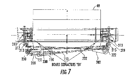
(0023] FIG. 7 is a top schematic view of the board feeder and the nail plate
extractor
assemblies shown in FIG. 3 in the in-position.
[0024] FIG. 8 is a side schematic view of one of the nail plate extractor
assemblies
shown in FIG. 6 in the in-position.
[0025] FIG. 9 is a side schematic view of one of the nail plate presser
assemblies shown
in FIG. 3 in the up-position holding a nail plate above an end of a board.
[0026]FIG. 10 is a side schematic view of the nail plate presser assembly
shown in FIG.
9 in the down-position pressing the nail plate into the end of the board.
[0027] FIG. 11 is a perspective view of one of the nail plate extractors (in
the in-position)
and one of the nail plate presser assemblies (in the down-position) shown in
FIG. 3
4
CA 03042994 2019-05-06
WO 2018/093480 PCT/US2017/055862
without the nail plate magazine in place.
[00281FIG. 12 is a partial side schematic view of the nail plate apparatus
shown in FIG.
3.
[0029]FIG. 13 is a partial front schematic view of the nail plate apparatus
shown in FIG.
3.
[0030]FIG. 14 is a flowchart illustrating a method for pressing nail plates
into ends of a
board using the nail plate apparatus shown in FIG. 3.
Detailed Description of the Preferred Embodiments
[0031]The present invention will now be described more fully hereinafter with
reference
to the accompanying drawings, in which preferred embodiments of the invention
are
shown. This invention may, however, be embodied in many different forms and
should
not be construed as limited to the embodiments set forth herein. Rather, these
embodiments are provided so that this disclosure will be thorough and
complete, and
will fully convey the scope of the invention to those skilled in the art. Like
numbers refer
to like elements throughout.
[0032]Referring initially to FIG. IT nail plates 20 may be used to increase
the resiliency
of wooden pallets. Each nail plate 20 is typically formed from a metal sheet
22, wherein
flanges are punched in the metal sheet so that they form projections 24. The
projections
24 extend outwards at right angles from the metal sheet 22. The projections 24
are on
one side of the metal sheet 22. The other side of the metal sheet 22 is flat
and is void of
any projections 24. This allows the nail plates 20 to be applied to their
respective boards
prior to assembly of the wooden pallet.
[0033]A partial cross-sectional view of an assembled wooden pallet 30 in FIG.
2
illustrates a nail plate 20 between a bottom connector board 40 and a support
block 50.
Since only about 2 inches of the end of the connector board 40 is nailed to
the support
block 50, the nail plate 20 greatly strengthens this board and improves the
impact
resistance when hit by a forklift or any other object.
[00341The other illustrated board in the base layer is an end deck board 42.
In the
cargo layer, the illustrated boards include a connector board 60, an end deck
board 62,
and an intermediate deck board 64. Nails 70 are used to secure the respective
boards
CA 03042994 2019-05-06
WO 2018/093480 PCT/US2017/055862
to the support block 50.
[0035]The nail plates 20 are pressed onto the ends of the connector boards 40
using a
nail plater apparatus 100, as illustrated in FIGS. 3 and 4. A block diagram of
the
illustrated nail plater apparatus 100 will also be referenced in FIG. 5. The
nail plater
apparatus 100 advantageously supports high speed production runs providing
plated
boards. For discussion purposes, the connector board 40 will be referred to as
a board
or as a plated board.
[0036] High speed production runs by the nail plate apparatus 100 are
supported by
simultaneously pressing the nail plates 20 onto the ends of each received
board 40. As
a board 40 is received, the nail plates 20 are simultaneously positioned over
the ends of
the board. After the nail plates 20 are pressed onto the ends of the received
board 40,
the plated board is then removed by the next board received board.
[0037] No mechanical mechanism is needed to remove the plated board 40 since
the
next board coming in pushes the plated board out. The speed and accuracy of
the nail
plater apparatus 100 advantageously allows a board 40 to be plated about every
1.7
seconds, which is about 2100 boards per hour.
[00381The nail plater apparatus 100 includes a board magazine 102 configured
to hold
boards 40 stacked in a vertical direction, and spaced apart nail plate
magazines 102.
Each nail plate magazine 104 is configured to hold nail plates 20 stacked in a
vertical
direction.
[0039]To assist the operator in loading the nail plates 20 in the respective
nail plate
magazines 102, angled or tilted nail plate holders 106 are adjacent each
respective nail
plate magazine 102. The operator uses a magnetic device to move a group of
nail
plates 20 in each nail plate holder 106 to an adjacent nail plate magazine
102.
[0040]Spaced apart nail plate extractor assemblies 110 are located under their
respective nail plate extractor guards 112. Each nail plate extractor assembly
110 is
associated with a respective nail plate magazine 102 and is configured to
position a nail
plate 20 therefrom to a respective nail plate pressing area 114.
[0041]A board feeder 120 is located under a board feeder guard 122, and is
configured
to position a board 40 from the board magazine 102 to a board receiving area
116. The
ends of the board 40 are aligned with the nail plates 20 positioned in the
respective nail
6
CA 03042994 2019-05-06
WO 2018/093480 PCT/US2017/055862
plate pressing areas 114.
(0042]Spaced apart nail plate presser assemblies 130 overlie the ends of the
board
receiving area 116 and are aligned with the respective nail plate pressing
areas 114.
The nail plate presser assemblies 130 are configured to press the nail plates
20 into the
ends of the board 40.
[0043]After a board 40 has the nail plates 20 pressed therein, the plated
board is then
pushed by the next received board to an accumulator apron 140. The plated
boards 40
may be stacked in groups of 5, for example. Once the stack receives the fifth
plated
board, spaced apart accumulator push arms 142 push the stack of plated boards
40
further out on the accumulator apron 140 so as to allow room for another stack
of plated
boards to form.
(0044]As will be discussed in greater detail below, the board feeder 120 and
the nail
plate extractor assemblies 110 are linked together. When the board feeder 120
is in the
out-position to allow a board 40 to drop into position from the board magazine
102, the
nail plate extractor assemblies 110 are also in the out-position to allow nail
plates 20 to
drop into position from the nail plate magazines 104. When the board feeder
120 is in
the in-position this causes the board 40 to be moved to the board receiving
area 116,
and the nail plate extractor assemblies 110 are also moved to the in-position
causing
the nail plates 20 to be moved to the nail plate pressing areas 114.
(0045]The nail plate presser assemblies 130 then press the nail plates 20 into
the ends
of the board 40 with the board feeder 120 and the nail plate extractor
assemblies 110
being in the in-position. After the nail plates 20 have been pressed into the
ends of the
board 40, the board feeder 120 returns to the out-position to allow a next
board to drop
into position from the board magazine 102 while the nail plate extractor
assemblies 110
also return to the out-position to allow the next nail plates 20 to drop into
position. This
cycle continuously repeats itself.
(0046]The board feeder 120 is powered by a pneumatic cylinder 150. Since the
nail
plate extractor assemblies 110 are linked to the board feeder 120, the nail
plate
extractor assemblies 110 move when the board feeder moves. The nail plate
presser
assemblies 130 are powered by a hydraulic pump 152.
[0047]A controller 160 is coupled to the pneumatic cylinder 150 and to the
hydraulic
7
CA 03042994 2019-05-06
WO 2018/093480 PCT/US2017/055862
pump 152 for control thereof. The controller 160 receives input from a board
feeder in-
position sensor 162, a board feeder out-position sensor 164 and a nail plate
presser
assembly up sensor 166. The respective sensors 162, 164, 166 may be proximity
sensors, for example.
[0048] The accumulator push arms 142 are also moved by a pneumatic cylinder
156.
The pneumatic cylinder 156 is coupled to the controller 160.
[0049]Referring now to FIGS. 6-8, the board feeder 120 and the nail plate
extractor
assemblies 110 will be discussed in greater detail. As noted above, the board
feeder
120 and the nail plate extractor assemblies 110 are linked together so that
the board 40
is positioned in the board receiving area 116 simultaneously when the nail
plates 20 are
positioned in the respective nail plate pressing areas 114.
[0050]The board feeder 120 includes a pair of spaced apart first and second
board
extractors 200, 202. The pair of spaced apart nail plate extractor assemblies
110
include a pair of spaced apart first and second nail plate extractors 210,
212.
[0051]Spaced apart first and second cams 220, 222 are each configured to
rotate
between an in-position and an out-position, with the first board extractor 200
coupled to
the first cam and the second board extractor 202 coupled to the second cam
222.
[00521 A first linkage 230 is coupled between the first cam 220 and the second
nail
plate extractor 212. A second linkage 232 is coupled between the second cam
222 and
the first nail plate extractor 210. Movement of the first and second cams 220,
222 is by
way of a push-pull pneumatic cylinder 150. One end of the pneumatic cylinder
150 is
coupled to the first cam 220 by linkage 151 and the other end of the pneumatic
cylinder
is coupled to the second cam 222 by linkage 153.
[00531When the first and second cams 220, 222 are rotated to the out-position,
as
shown in FIG. 6, a board 40 is dropped from the board magazine 102 to a board
staging
area adjacent the spaced apart first and second board extractors 200, 202.
Nail plates
20 are dropped from the nail plate magazines 104 to nail plate staging areas
adjacent
the first and second nail plate extractors 210, 212.
[0054]When the first and second cams 220, 222 are rotated to the in-position,
as shown
in FIG. 7, the board 40 is positioned from the board staging area to the board
receiving
area 116 by the first and second board extractors 200, 202. The nail plates 20
are
8
CA 03042994 2019-05-06
WO 2018/093480 PCT/US2017/055862
simultaneously positioned from the nail plate staging areas to the nail plate
receiving
areas 114 by the first and second nail plate extractors 210, 212.
[0055]When the first and second cams 220, 222 are rotated back to the out-
position, a
next board 40 is dropped from the board magazine 102 to the board staging area
and
next nail plates 20 are dropped from the nail plate magazines 104 to the nail
plate
staging areas.
[0056] When the first and second cams 220, 222 are rotated back to the in-
position, the
next board 40 is used to push the plated board from the board receiving area
116 to the
adjacent accumulator apron 140. In other words, no mechanical mechanism is
needed
to remove the plated board 40 since the next board coming in pushes the plated
board
out. The speed and accuracy of the nail plater apparatus 100 advantageously
allows a
board 40 to be plated about every 1.7 seconds, which is about 2100 boards per
hour.
(0057] The pair of spaced apart nail plate extractor assemblies 110 further
include a pair
of spaced apart first and second arms 213, 215. The first arm 213 is coupled
to the
second linkage 232 and the second arm 215 is coupled to the first linkage 230.
A first
arm shaft 217 is coupled between the first arm 217 and the first nail plate
extractor 210.
Similarly, a second arm shaft 219 is coupled between the second arm 215 and
the
second nail plate extractor 212. The first and second arms 213, 215 and the
corresponding first and second arm shafts 217, 219 insure that the first and
second nail
plated 210, 212 move in synch with the first and second board extractors 200,
202.
[0058] Referring now to FIGS. 9-11, each nail plate presser assembly 130
includes a
hydraulic ram 131, a press foot 133 coupled to the hydraulic ram, and a pair
of spaced
apart nail plate retainer jaws 135 pivotly coupled to the press foot. The nail
plate
retainer jaws 135 are configured to hold the nail plate 20 when positioned in
the nail
plate receiving area 114. The pair of nail plate retainer jaws 135 pivotly
move to release
the nail plate 20 when the hydraulic ram 131 causes the nail plate to be
pressed into the
end of the board 40.
[0059] FIG. 11 provides a perspective view of one of the nail plate extractors
210 (in the
in-position) and one of the nail plate presser assemblies 130 (in the down-
position)
without the nail plate magazine in place. When the nail plate extractor 210 is
in the
retracted or out-positon, a nail plate 20 is dropped from the nail plate
magazine 104
9
CA 03042994 2019-05-06
WO 2018/093480 PCT/US2017/055862
onto a pair of spaced apart rails 113. As the nail plate extractor 210 is
moved to the in-
positon, the nail plate is moved to the nail plate receiving area 114 under
the press foot
133.
[0060] Referring now to FIGS. 12-13, an accumulator apron 140 is positioned to
receive
the boards 40 after the nail plates 20 have been pressed into the ends thereof
by the
nail plate presser assemblies 130. A pair of spaced apart accumulator push
arms 142
adjacent the accumulator apron 140 is configured to push the boards 40 after a
predetermined number of boards have been stacked on the accumulator apron. The
accumulator push arms 142 are powered by a pneumatic cylinder 154.
[0061] Referring now to the flowchart 300 shown in FIG. 14, another aspect is
directed
to a method for pressing nail plates 20 into ends of a board 40 using a nail
plate
apparatus 100 as described above. From the start (Block 302), the method
comprises
stacking a plurality of boards 40 in a board magazine 104 at Block 304, and
stacking a
plurality of nail plates 20 in a pair of spaced apart nail plate magazines 104
at Block
306.
[0062]A pair of spaced apart nail plate extractor assemblies 110 is operated
at Block
308, with each nail plate extractor assembly associated with a respective nail
plate
magazine 104, to position a nail plate 20 therefrom to a respective nail plate
pressing
area 114. A board feeder 120 is operated at Block 310 to position a board 40
from the
board magazine 102 to a board receiving area 116, with ends of the board being
aligned with the nail plates positioned in the respective nail plate pressing
areas 114. A
pair of spaced apart nail plate presser assemblies 130 overlies ends of the
board
receiving area 116 and aligned with the respective nail plate pressing areas
114 and is
operated at Block 312 to press the nail plates 20 into the ends of the board
40. The
method ends at Block 314.
(0063]Many modifications and other embodiments of the invention will come to
the
mind of one skilled in the art having the benefit of the teachings presented
in the
foregoing descriptions and the associated drawings. Therefore, it is
understood that the
invention is not to be limited to the specific embodiments disclosed, and that
modifications and embodiments are intended to be included as readily
appreciated by
those skilled in the art.