Note: Descriptions are shown in the official language in which they were submitted.
54933/CNHW-213
SYSTEM AND METHOD FOR DETERMINING FORCES EXERTED ON
ROLLING GROUND ENGAGING COMPONENTS OF AN AGRICULTURAL
IMPLEMENT BASED ON AN APPLIED BRAKING FORCE
FIELD OF THE INVENTION
[0001] The present disclosure generally relates to agricultural
implements and,
more particularly, to systems and methods for determining forces exerted on
rolling
ground engaging components of an agricultural implement based on an applied
braking force.
BACKGROUND OF THE INVENTION
[0002] Modern farming practices strive to increase yields of
agricultural fields. In
this respect, agricultural implements are towed behind a tractor or other work
vehicle
to disperse seeds and other agricultural products throughout a field and/or
condition
the soil. An agricultural implement typically includes one or more rolling
ground
engaging components that are configured to roll relative to the soil as the
implement
is moved across a field. For example, in certain configurations, the implement
may
include one or more disc openers that form a furrow or trench within the soil
while
rolling relative to the soil. Furthermore, the implement may also include one
or more
closing discs that close the furrow while rolling relative to the soil. As the
implement
is moved across the field, the soil exerts a force or a rolling resistance on
the rolling
ground engaging components. Such force may be indicative of one or more
characteristics of the soil within the field across which the implement is
being moved.
[0003] Accordingly, an improved system and method for determining forces
exerted on rolling ground engaging components of an agricultural implement
would
be welcomed in the technology.
SUMMARY OF THE INVENTION
[0004] Aspects and advantages of the technology will be set forth in
part in the
following description, or may be obvious from the description, or may be
learned
through practice of the technology.
[0005] In one aspect, the present subject matter is directed to a system
for
determining forces exerted on rolling ground engaging components of an
agricultural
1
CA 3043056 2019-05-13
54933/CNHW-213
implement. The system may include a rolling ground engaging component
configured to roll relative to soil within a field as the agricultural
implement is moved
across the field. The system may also include a braking device configured to
apply a
braking force to the rolling ground engaging component. Furthermore, the
system
may include a sensor configured to detect a parameter indicative of a
rotational speed
of the rolling ground engaging component. Additionally, the system may include
a
controller communicatively coupled to the sensor. The controller may be
configured
to control an operation of the braking device such that a braking force is
applied to the
rolling ground engaging component. When the braking force is being applied to
the
rolling ground engaging component, the controller may be configured to monitor
the
rotational speed of the rolling ground engaging component based on measurement
signals received from the sensor. Moreover, the controller may be configured
to
determine a force exerted on the rolling ground engaging component by the soil
within the field based on the applied braking force and the monitored
rotational speed.
[0006] In another aspect, the present subject matter is directed to a
system for
determining forces exerted on rolling ground engaging components of an
agricultural
implement. The system may include a rolling ground engaging component
configured to roll relative to soil within a field as the agricultural
implement is moved
across the field. The system may also include a braking device configured to
apply a
braking force to the rolling ground engaging component. Furthermore, the
system
may include a sensor configured to detect a parameter indicative of a
rotational speed
of the rolling ground engaging component. Additionally, the system may include
a
controller communicatively coupled to the sensor. The controller may be
configured
to control an operation of the braking device in a manner that adjusts the
braking
force being applied to the rolling ground engaging component. When the braking
force is being adjusted, the controller may be configured to monitor the
rotational
speed of the rolling ground engaging component based on measurement signals
received from the sensor. Moreover, the controller may be configured to
determine a
force exerted on the rolling ground engaging component by the soil within the
field
based on a magnitude of an adjustment of the braking force and the monitored
rotational speed.
2
CA 3043056 2019-05-13
54933/CNHW-213
[0007] In a further aspect, the present subject matter is directed to a
method for
determining forces exerted on rolling ground engaging components of an
agricultural
implement. The seed-planting implement may include a rolling ground engaging
component configured to roll relative to soil within a field as the
agricultural
implement is moved across the field. The method may include controlling, with
the
computing device, an operation of a braking device such that a braking force
is
applied to the rolling ground engaging component. When the braking force is
being
applied to the rolling ground engaging component, the method may include
monitoring, with the computing device, a rotational speed of the rolling
ground
engaging component. Furthermore, the method may include determining, with the
computing device, a force exerted on the rolling ground engaging component
based
on the applied braking force and the monitored rotational speed.
[0008] These and other features, aspects and advantages of the present
technology
will become better understood with reference to the following description and
appended claims. The accompanying drawings, which are incorporated in and
constitute a part of this specification, illustrate embodiments of the
technology and,
together with the description, serve to explain the principles of the
technology.
BRIEF DESCRIPTION OF THE DRAWINGS
[0009] A full and enabling disclosure of the present technology,
including the best
mode thereof, directed to one of ordinary skill in the art, is set forth in
the
specification, which makes reference to the appended figures, in which:
[0010] FIG. I illustrates a perspective view of one embodiment of an
agricultural
implement in accordance with aspects of the present subject matter;
[0011] FIG. 2 illustrates a side view of one embodiment of a row unit
suitable for
use with an agricultural implement in accordance with aspects of the present
subject
matter;
[0012] FIG. 3 illustrates a front view of one embodiment of a braking
force
transmission assembly in accordance with aspects of the present subject
matter,
particularly illustrating the assembly configured to transmit a braking force
from a
braking device to a closing disc of an agricultural implement;
3
CA 3043056 2019-05-13
54933/CNHW-213
[0013] FIG. 4 illustrates a partial, side view of the braking force
transmission
assembly shown in FIG. 3, particularly illustrating a clutch of the system in
accordance with aspects of the present subject matter;
[0014] FIG. 5 illustrates a schematic view of one embodiment of a system
for
determining forces exerted on rolling ground engaging components of an
agricultural
implement in accordance with aspects of the present subject matter;
[0015] FIG. 6 is a flow diagram of one embodiment of a method for
determining
forces exerted on rolling ground engaging components of an agricultural
implement in
accordance with aspects of the present subject matter; and
[0016] FIG. 7 is a flow diagram of another embodiment of a method for
determining forces exerted on rolling ground engaging components of an
agricultural
implement in accordance with aspects of the present subject matter.
[0017] Repeat use of reference characters in the present specification
and
drawings is intended to represent the same or analogous features or elements
of the
present technology.
DETAILED DESCRIPTION OF THE DRAWINGS
[0018] Reference now will be made in detail to embodiments of the
invention,
one or more examples of which are illustrated in the drawings. Each example is
provided by way of explanation of the invention, not limitation of the
invention. In
fact, it will be apparent to those skilled in the art that various
modifications and
variations can be made in the present invention without departing from the
scope or
spirit of the invention. For instance, features illustrated or described as
part of one
embodiment can be used with another embodiment to yield a still further
embodiment. Thus, it is intended that the present invention covers such
modifications
and variations as come within the scope of the appended claims and their
equivalents.
[0019] In general, the present subject matter is directed to systems and
methods
for determining forces exerted on rolling ground engaging components of an
agricultural implement, such as a seed-planting implement. Specifically, in
several
embodiments, as the implement is being moved across a field, a controller of
the
disclosed system may be configured to control the operation of a braking
device of the
implement such that a braking force is applied or adjusted to a rolling ground
4
CA 3043056 2019-05-13
54933/CNHW-213
engaging component(s) of the implement, such as one or more gauge wheels, disc
openers, closing discs, press wheels, or residue removal wheels. The braking
force(s)
may, in turn, cause the rotational speed(s) of the rolling ground engaging
component(s) to change, with the change(s) in rotational speed generally being
indicative of the force(s) being applied to the rolling ground engaging
component(s)
by the soil within the field. As such, the controller may be configured to
monitor the
rotational speed(s) of the rolling ground engaging component(s) as the braking
force(s) is being applied to or adjusted on the rolling ground engaging
component(s).
The controller may then be configured to determine the force(s) exerted on the
rolling
ground engaging component(s) by the soil based on the applied braking force(s)
and
the monitored rotational speed(s). Thereafter, the controller may be
configured to
determine a soil characteristic(s), such as soil density, soil plasticity,
soil moisture,
soil texture, and/or soil cohesion, of the soil within the field based on the
determined
force(s). Furthermore, in one embodiment, the controller may also be
configured to
adjust one or more operating parameters of the implement or an associated work
vehicle, such as the downforce being applied to the rolling ground engaging
component(s) and/or the ground speed of the work vehicle, based on the
determined
force(s).
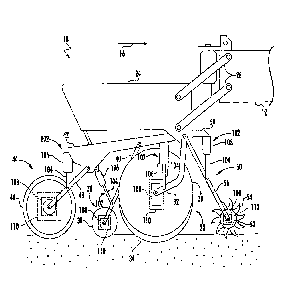
[0020] Referring now to the drawings, FIG. 1 illustrates a perspective
view of one
embodiment of an agricultural implement 10 in accordance with aspects of the
present
subject matter. It should be appreciated that, although the implement 10
illustrated
herein corresponds to a planter, the implement 10 may generally correspond to
any
suitable equipment or implement, such as a seeder (e.g., a seed disc drill) or
another
seed-planting implement, a side dresser or another fertilizer dispensing
implement, a
strip tiller, a disc harrow or other tillage implement, and/or the like.
[0021] As shown in FIG. 1, the implement 10 may include a laterally
extending
toolbar or frame assembly 12 connected at its middle to a forwardly extending
tow
bar 14 to allow the implement 10 to be towed by a work vehicle (not shown),
such as
an agricultural tractor, in a direction of travel (e.g., as indicated by arrow
16 in FIG.
1). The toolbar 12 may generally be configured to support a plurality of seed
planting
units (or row units) 18. As is generally understood, each row unit 18 may be
configured to deposit seeds at a desired depth beneath the soil surface and at
a desired
CA 3043056 2019-05-13
54933/CNHW-213
seed spacing as the implement 10 is being towed by the work vehicle, thereby
establishing rows of planted seeds. In some embodiments, the bulk of the seeds
to be
planted may be stored in one or more hoppers or seed tanks 20. Thus, as seeds
are
planted by the row units 18, a pneumatic distribution system may distribute
additional
seeds from the seed tanks 20 to the individual row units 18. Additionally, one
or
more fluid tanks 22 may store agricultural fluids, such as insecticides,
herbicides,
fungicides, fertilizers, and/or the like.
[0022] It should be appreciated that, for purposes of illustration, only
a portion of
the row units 18 of the implement 10 have been shown in FIG. 1. In general,
the
implement 10 may include any number of row units 18, such as six, eight,
twelve,
sixteen, twenty-four, thirty-two, or thirty-six row units. In addition, it
should be
appreciated that the lateral spacing between row units 18 may be selected
based on the
type of crop being planted. For example, the row units 18 may be spaced
approximately thirty inches from one another for planting corn, and
approximately
fifteen inches from one another for planting soybeans.
[0023] It should also be appreciated that the configuration of the
agricultural
implement 10 described above and shown in FIG. 1 is provided only to place the
present subject matter in an exemplary field of use. Thus, it should be
appreciated
that the present subject matter may be readily adaptable to any manner of
implement
configuration.
[0024] Referring now to FIG. 2, a side view of one embodiment of a row
unit 18
is illustrated in accordance with aspects of the present subject matter. As
shown, the
row unit 18 may include a frame 24 adjustably coupled to the toolbar 12 by
links 26.
For example, one end of each link 26 may be pivotably coupled to the frame 24,
while
an opposed end of each link 26 may be pivotably coupled to the toolbar 12. In
one
embodiment, the links 26 may be parallel. However, it should be appreciated
that, in
alternative embodiments, the row unit 18 may be coupled to the toolbar 12 in
any
other suitable manner. For example, the links 26 may be fixedly coupled to the
frame
24 and/or the links 26 may be non-parallel. Additionally, in a further
embodiment,
the implement 10 may not include the links 26. In such instance, the implement
10
may include other components for coupling each row unit 18 to the toolbar 12.
6
CA 3043056 2019-05-13
54933/CNHW-213
=
[0025] As shown in FIG. 2, the row unit 18 also includes a furrow
opening
assembly 28. For example, in one embodiment, the furrow opening assembly 28
may
include a gauge wheel 30 and one or more disc openers 34 configured to
excavate a
furrow or trench in the soil. As is generally understood, the gauge wheel 30
may be
configured to engage the top surface of the soil as the implement 10 is moved
across
the field. In this regard, the height of the disc opener(s) 34 may adjusted
with respect
to the position of the gauge wheel 30 to set the desired depth of the furrow
being
excavated. Furthermore, the furrow opening assembly 28 may include a support
arm
32 configured to adjustably couple the gauge wheel 30 and the disc opener(s)
34 to
the frame assembly 24. For example, one end of the support arm 32 may be
pivotably
coupled to the gauge wheel 30 and the disc opener(s) 34, while an opposed end
of the
support arm 32 may be pivotably coupled to the frame 24. However, it should be
appreciated that, in alternative embodiments, the gauge wheel 30 and the disc
opener(s) 34 may be coupled to the frame 24 in any other suitable manner.
[0026] Moreover, as shown, the row unit 18 may include a furrow closing
assembly 36. Specifically, in several embodiments, the furrow closing assembly
28
may include a pair of closing discs 38 (only of which is shown) positioned
relative to
each other in a manner that permits soil to flow between the discs 38 as the
implement
is being moved across the field. As such, the closing discs 38 may be
configured
to close the furrow after seeds have been deposited therein, such as by
pushing the
excavated soil into the furrow. Furthermore, the furrow closing assembly 36
may
include a support arm 40 configured to adjustably couple the closing discs 38
to the
frame assembly 24. For example, one end of the support arm 40 may be pivotably
coupled to the closing discs 38, while an opposed end of the support arm 40
may be
pivotably coupled to a chassis arm 42, which is, in turn, coupled to the frame
24.
However, it should be appreciated that, in alternative embodiments, the
closing discs
38 may be coupled to the frame 24 in any other suitable manner. Furthermore,
it
should be appreciated that, in alternative embodiments, the furrow closing
assembly
36 may include any other suitable number of closing discs 38, such as one
closing
disc 38 or three or more closing discs 38.
[0027] Additionally, the row unit 18 may include a press wheel assembly
44.
Specifically, in several embodiments, the press wheel assembly 44 may include
a
7
CA 3043056 2019-05-13
54933/CNHW-213
press wheel 46 configured to roll over the closed furrow to firm the soil over
the seed
and promote favorable seed-to-soil contact. Furthermore, the press wheel
assembly
44 may include a support arm 48 configured to adjustably couple the press
wheel 46
to the frame assembly 24. For example, one end of the support arm 48 may be
pivotably coupled to the press wheel 48, while an opposed end of the support
arm 48
may be pivotably coupled to the chassis arm 42, which is, in turn, coupled to
the
frame 24. However, it should be appreciated that, in alternative embodiments,
the
press wheel 46 may be coupled to the frame 24 in any other suitable manner.
[0028] Furthermore, in one embodiment, a residue removal device 50 may
be
positioned at the forward end of the row unit 18 relative to the direction of
travel 16.
In this regard, the residue removal device 50 may be configured to break up
and/or
sweep away residue, dirt clods, and/or the like from the path of the row unit
18 before
the furrow is formed in the soil. For example, in one embodiment, the residue
removal device 50 may include one or more residue removal wheels 52, with each
wheel 52 having a plurality of tillage points or fingers 54. As such, the
wheel(s) 52
may be configured to roll relative to the soil as the implement 10 is moved
across the
field such that the fingers 54 break up and/or sweep away residue and dirt
clods.
Additionally, the residue removal device 50 may include a support arm 56
configured
to adjustably couple the residue removal wheel(s) 52 to the frame assembly 24.
For
example, one end of the support arm 56 may be pivotably coupled to the
wheel(s) 52,
while an opposed end of the support arm 56 may be pivotably coupled to the
frame
24. However, it should be appreciated that, in alternative embodiments, the
residue
removal wheel(s) 52 may be coupled to the frame 24 in any other suitable
manner.
Furthermore, although only one residue removal wheel 52 is shown in FIG. 2, it
should be appreciated that, in alternative embodiments, the residue removal
device 50
may include any other suitable number of residue removal wheels 52. For
example,
in one embodiment, the residue removal device 50 may include a pair of residue
removal wheels 52.
[0029] In several embodiments, the row unit 18 may include one or more
actuators 102. Specifically, each actuator 102 may be configured to adjust to
the
position of a rolling ground engaging component of the row unit 18 relative to
the
frame 24. As used herein, a rolling ground engaging component may be any
8
CA 3043056 2019-05-13
54933/CNHW-213
component of the implement 10 configured to roll relative to the soil as the
implement
is moved across a field. For example, in one embodiment, a first end of each
actuator 102 (e.g., a rod 104 of each actuator 102) may be coupled to an arm
on which
the rolling ground engaging component is mounted, while a second end of each
actuator 102 (e.g., the cylinder 106 of each actuator 102) may be coupled to
the
chassis arm 42 or a bracket 58, which are, in turn, coupled to the frame 24.
The rod
104 of each actuator 102 may be configured to extend and/or retract relative
to the
corresponding cylinder 106 to adjust the downforce being applied to and/or the
penetration depth of the associated rolling ground engaging component. In one
embodiment, the actuator(s) 102 corresponds to a fluid-driven actuator(s),
such as a
hydraulic or pneumatic cylinder(s). However, it should be appreciated that the
actuator(s) 102 may correspond to any other suitable type of actuator(s), such
as an
electric linear actuator(s). Furthermore, it should be appreciated that, in
alternative
embodiments, the actuator(s) 102 may be configured to adjust to the
position(s) of any
other rolling ground engaging component(s) of the row unit 18, such as the
disc
opener(s) 34.
[0030] As shown in FIG. 2, the actuator(s) 102 may be configured to
adjust the
downforce being applied to and/or the penetration depth of any number of
rolling
ground engaging components of the row unit 18. Specifically, in several
embodiments, the actuator(s) 102 may configured to adjust the downforce being
applied to one or more rolling ground engaging components of the furrow
opening
assembly 28, the furrow closing assembly 36, the press wheel assembly 44,
and/or the
residue removal device 50. For instance, as shown in the illustrated
embodiment, an
actuator 102 may configured to adjust the downforce being applied to the gauge
wheel 30, the closing disc(s) 38, the press wheel 46, and the residue removal
wheel(s)
52. Furthermore, in the illustrated embodiment, the actuators 102 may be
configured
to adjust the penetration depth of the closing disc(s) 38. Alternatively, the
actuator(s)
102 may be provided in operative association with any other suitable rolling
ground
engaging components of the row unit 18, such as the disc opener(s) 34.
[0031] Moreover, in several embodiments, the row unit 18 may include one
or
more rotational speed sensors 108. Specifically, each rotational speed sensor
108 may
be configured to detect a parameter associated with the rotational speed of an
9
CA 3043056 2019-05-13
54933/CNHW-213
associated rolling ground engaging component of the row unit 18. For example,
in
one embodiment, each rotational speed sensor 108 may be configured as a Hall
Effect
sensor configured to detect the rotational speed of the associated rolling
ground
engaging component. However, it should be appreciated that, in alternative
embodiments, the rotational speed sensor(s) 108 may be configured as any other
suitable device(s) for sensing or detecting the rotational speed(s) or
position(s) of the
one or more rolling ground engaging component(s) of the row unit 18.
[0032] Furthermore, as shown in FIG. 2, the rotational speed sensor(s)
108 may
be provided in operative association with any number of rolling ground
engaging
components of the row unit 18. Specifically, in several embodiments, the
rotational
speed sensor(s) 108 may be provided in operative association with one or more
rolling
ground engaging components of the furrow opening assembly 28, the furrow
closing
assembly 36, the press wheel assembly 44, and/or the residue removal device
50. For
instance, as shown in the illustrated embodiment, a rotational speed sensor
108 may
be provided in operative association with the gauge wheel 30, one of the
closing discs
38, the press wheel 46, and one of the residue removal wheels 52.
Alternatively, the
rotational speed sensor(s) 108 may be provided in operative association with
any
other suitable rolling ground engaging components of the row unit 18, such as
the disc
opener(s) 34 and/or additional closing discs 38 or residue removal wheels 52.
[0033] In accordance with aspects of the present subject matter, the row
unit 18
may include one or more braking devices 110. Specifically, each braking device
110,
when activated, may be configured to apply a braking force to an associated
rolling
ground engaging component of the row unit 18. For example, in one embodiment,
the
braking device(s) 110 may correspond to a non-contact-based braking device(s),
such
as a hysteresis brake(s). In general, a hysteresis brake may include a rotor
or drag cup
positioned within a pole structure such that an air gap is defined between the
rotor and
the pole structure. As such, the rotor may be configured to rotate relative to
the pole
structure. When a field coil embedded within the rotor is magnetized (e.g., by
applying an electric current thereto), a magnetic torque is generated within
the air gap.
The magnetic torque may, in turn, cause the rotor to rotate in a manner that
creates a
braking force. In another embodiment, the braking device(s) 110 may correspond
to a
suitable hydraulic cylinder(s) or an electric actuator(s) configured to push a
stationary
CA 3043056 2019-05-13
54933/CNHW-213
frictional element(s), such as a brake shoe(s) or a brake caliper(s), against
a rotating
element(s), such as a brake drum(s) or a brake disc(s). However, it should be
appreciated that, in alternative embodiments, the braking device(s) 110 may be
configured as any other suitable device(s) for applying a braking force(s) to
one or
more rolling ground engaging components of the row unit 18.
[0034] Additionally, as shown in FIG. 2, the braking device(s) 110 may
be
provided in operative association with any number of rolling ground engaging
components of the row unit 18. Specifically, in several embodiments, the
braking
device(s) 110 may be provided in operative association with one or more
rolling
ground engaging components of the furrow opening assembly 28, the furrow
closing
assembly 36, the press wheel assembly 44, and/or the residue removal device
50. For
instance, as shown in the illustrated embodiment, a braking device 110 may be
provided in operative association with the gauge wheel 30, one of the closing
discs
38, the press wheel 46, and one of the residue removal wheels 52. In one
embodiment, the braking device(s) 110 may be provided in operative association
with
the rolling ground engaging component(s) of the row unit 18 to which a
rotational
speed sensor(s) 108 is operatively associated. Alternatively, the rotational
speed
sensor(s) 108 may be provided in operative association with any other suitable
rolling
ground engaging components of the row unit 18, such as the disc opener(s) 34
and/or
additional closing discs 38 or residue removal wheels 52.
[0035] It should be appreciated that the configuration of the row unit
18 described
above and shown in FIG. 2 is provided only to place the present subject matter
in an
exemplary field of use. Thus, it should be appreciated that the present
subject matter
may be readily adaptable to any manner of row unit configuration.
[0036] Referring now to FIGS. 3 and 4, differing views of one embodiment
of a
braking force transmission assembly 60 of the row unit 18 are illustrated in
accordance with aspects of the present subject matter. Specifically, FIG. 3
illustrates
a front view of the transmission assembly 60, particularly illustrating
various
components thereof. Additionally, FIG. 4 illustrates a partial, side view of
the
transmission assembly 60, particularly illustrating a clutch 62 of the
assembly 60. As
shown in FIG. 3, the transmission assembly 60 may be configured to transmit a
braking force from a braking device 110 of the row unit 18 to one of the
closing discs
11
CA 3043056 2019-05-13
54933/CNHW-213
38 of the furrow closing assembly 36. However, it should be appreciated that
any
suitable transmission assembly may be utilized to transmit the braking force
from the
braking device 110 to the closing disc 38. Furthermore, it should be
appreciated that
the disclosed transmission assembly 60 may be configured to transmit a braking
force
from any braking device 110 of the row unit 18 to any rolling ground engaging
component of the row unit 18, such as the gauge wheel 30, the disc opener(s)
34, the
press wheel 46, and/or the residue removal wheel 52.
[0037] As shown in FIG. 3, the transmission assembly 60 may include a
flexible,
endless member 64 configured to transmit the braking force from the braking
device
110 to the closing disc 38. More specifically, in the illustrated embodiment,
the
braking device 110 may be configured as a non-contact-based braking device
mounted on the chassis arm 42 of the row unit 18 at a position located
generally
above the closing discs 38. In this regard, the member 64 may be configured to
frictionally engage a pulley 66 coupled to an output shaft 112 of the braking
device
110 and a pulley 68 coupled to an axle 70 on which the closing disc 38 is
mounted.
When the braking device 110 is activated, its output shaft 112 may rotate in
the
opposite direction of the rotation of the axle 70. As such, the member 64 may
be
configured to transmit the rotational energy from the output shaft 112 to the
axle 70.
Such rotational energy may be in the direction opposite of the rotation of the
axle 70,
thereby providing a braking force to the closing disc 38. It should be
appreciated that
the flexible, endless member 64 may be configured as a belt (e.g., V-belts), a
chain, or
any other suitable member for transmitting rotational energy between the
braking
device 110 and the closing disc 38. Furthermore, it should be appreciated
that, in
alternative embodiments, the braking device 110 may be directly coupled to or
otherwise integrated into the axle 70 such that the magnetic torque generated
by the
braking device 110 is directly applied to the axle 70.
[0038] Referring now to FIG. 4, the transmission assembly 60 may include
a
clutch 62. For example, as shown, in one embodiment, the clutch 62 may be
coupled
between the axle 70 of the closing disc 38 and the associated pulley 68. As
such,
when the clutch 62 is disengaged, the clutch 62 may be configured to permit
the
closing discs 38 and the axle 70 to rotate without also rotating the flexible
member 64
and the output shaft 112 of the braking device 110. Conversely, when the
clutch 62 is
12
CA 3043056 2019-05-13
54933/CNHW-213
engaged, the clutch 62 may be configured to mechanically couple the axle 70
and the
associated pulley 68 in a manner that transmits the braking force from the
braking
device 110 to the closing disc 38. However, it should be appreciated that, in
alternative embodiments, the clutch 68 may be coupled between the output shaft
112
and the associated pulley 66. In such embodiments, the clutch 62 may be
configured
to permit the closing disc 38, the axle 70, and the flexible member 64 to
rotate without
also rotating the corresponding output shaft 112 of the braking device 110.
[0039] Moreover, it should be appreciated that the clutch 62 may be
configured as
any suitable device that permits selective engagement and disengagement of the
braking device 110 and the closing disc 38. For example, in one embodiment,
the
clutch 62 may include a suitable actuator (e.g., an electric linear actuator)
configured
to engage and disengage a pair of friction plates, with one friction plate
being coupled
to the braking device 110 and the other friction plate and coupled to the
closing disc
38. Conversely, in another embodiment, the clutch 62 may be configured as a
purely
mechanical device, such as a Sprag clutch.
[0040] Additionally, it should be appreciated that the configuration of
the brake
force transmission assembly 60 described above and shown in FIGS. 3 and 4 is
provided only to place the present subject matter in an exemplary field of
use. Thus,
it should be appreciated that the present subject matter may be readily
adaptable to
any manner of transmission assembly configuration.
[0041] Referring now to FIG. 5, a schematic view of one embodiment of a
system
100 for determining forces exerted on rolling ground engaging components of an
agricultural implement is illustrated in accordance with aspects of the
present subject
matter. In general, the system 100 will be described herein with reference to
the
implement 10, the row unit 18, and the transmission assembly 60 described
above
with reference to FIGS. 1-4. However, it should be appreciated by those of
ordinary
skill in the art that the disclosed system 100 may generally be utilized with
s
agricultural implements having any other suitable implement configuration, row
units
having any other suitable row unit configuration, and/or transmission
assemblies
having any other suitable assembly configuration.
[0042] As shown in FIG. 5, the system 100 may include a controller 114
configured to electronically control the operation of one or more components
of the
13
CA 3043056 2019-05-13
¨ õ
54933/CNHW-213
implement 10. In general, the controller 114 may comprise any suitable
processor-
based device known in the art, such as a computing device or any suitable
combination of computing devices. Thus, in several embodiments, the controller
114
may include one or more processor(s) 116 and associated memory device(s) 118
configured to perform a variety of computer-implemented functions. As used
herein,
the term "processor" refers not only to integrated circuits referred to in the
art as
being included in a computer, but also refers to a controller, a
microcontroller, a
microcomputer, a programmable logic controller (PLC), an application specific
integrated circuit, and other programmable circuits. Additionally, the memory
device(s) 118 of the controller 114 may generally comprise memory element(s)
including, but not limited to, a computer readable medium (e.g., random access
memory (RAM)), a computer readable non-volatile medium (e.g., a flash memory),
a
floppy disk, a compact disc-read only memory (CD-ROM), a magneto-optical disk
(MOD), a digital versatile disc (DVD) and/or other suitable memory elements.
Such
memory device(s) 118 may generally be configured to store suitable computer-
readable instructions that, when implemented by the processor(s) 116,
configure the
controller 114 to perform various computer-implemented functions, such as one
or
more aspects of the methods 200 and 300 described below with reference to
FIGS. 6
and 7. In addition, the controller 114 may also include various other suitable
components, such as a communications circuit or module, one or more
input/output
channels, a data/control bus and/or the like.
[0043] It should be appreciated that the controller 114 may correspond
to an
existing controller of the implement 10 or an associated work vehicle (not
shown) or
the controller 114 may correspond to a separate processing device. For
instance, in
one embodiment, the controller 114 may form all or part of a separate plug-in
module
that may be installed within the implement 10 or associated work vehicle to
allow for
the disclosed system and method to be implemented without requiring additional
software to be uploaded onto existing control devices of the implement 10 or
the
associated work vehicle.
[0044] Furthermore, in one embodiment, the system 100 may also include a
user
interface 120. More specifically, the user interface 120 may be configured to
provide
feedback (e.g., notifications associated with forces exerted on rolling ground
engaging
14
CA 3043056 2019-05-13
54933/CNHW-213
components of the implement 10) to the operator of the implement 10. As such,
the
user interface 120 may include one or more feedback devices (not shown), such
as
display screens, speakers, warning lights, and/or the like, which are
configured to
communicate such feedback. In addition, some embodiments of the user interface
120 may include one or more input devices (not shown), such as touchscreens,
keypads, touchpads, knobs, buttons, sliders, switches, mice, microphones,
and/or the
like, which are configured to receive user inputs from the operator. In one
embodiment, the user interface 120 may be positioned within a cab of a work
vehicle
configured to tow the implement 10 across the field. However, in alternative
embodiments, the user interface 120 may have any suitable configuration and/or
be
positioned in any other suitable location.
[0045] In several embodiments, the controller 114 may be configured to
control
the operation of the braking device(s) 110 such that a braking force is
applied to one
or more rolling ground engaging components of the implement 10, such as the
gauge
wheel 30, the disc opener(s) 34, the closing disc(s) 38, the press wheel 46,
and/or the
residue removal wheel(s) 52. Specifically, as shown in FIG. 5, the controller
114 may
be communicatively coupled to the braking device(s) 110 via a wired or
wireless
connection to allow control signals (e.g., as indicated by dashed lines 122 in
FIG. 5)
to be transmitted from the controller 114 to the braking device(s) 110. In
this regard,
the controller 114 may be configured to transmit control signals 122 to the
braking
device(s) 110 instructing the braking device(s) 110 to apply a braking force
to the
associated rolling ground engaging component(s). In general, the amount or
magnitude of the applied braking force may be a known value. Alternatively,
the
controller 114 may be configured to transmit control signals 122 to the
braking
device(s) 110 instructing the braking device(s) 110 to adjusted (e.g.,
increase or
decrease) the braking force being applied to the associated rolling ground
engaging
component(s). The amount or magnitude of the change in braking force may be a
known value.
[0046] In one embodiment, the controller 114 may be configured to
control the
operation of the clutch(es) 62 when the braking force is applied to one or
more rolling
ground engaging components of the implement 10. As indicated above, the
clutch(es)
62 may be configured to selectively transmit the braking force(s) from the
associated
CA 3043056 2019-05-13
54933/CNHW-213
braking device(s) 110 to the associated rolling ground engaging component(s).
In this
regard, as shown in FIG. 5, the controller 114 may be communicatively coupled
to the
clutch(es) 62 (e.g., an actuator(s) of the clutch(es) 62) via a wired or
wireless
connection to allow control signals 122 to be transmitted from the controller
114 to
the clutch(es) 62. As such, when the braking device(s) 110 is activated, the
controller
114 may be configured to transmit control signals 122 to the corresponding
clutch(es)
62 instructing the clutch(es) 62 to engage in a manner that transmits the
braking
force(s) from the corresponding braking device(s) 110 to the corresponding
rolling
ground engaging component(s). Alternatively, the braking force(s) may be
transmitted directly from the braking device(s) 110 to the associated rolling
ground
engaging component(s) without requiring control of any other component(s) of
the
system 100 coupled between the braking device(s) 110 and the associated
rolling
ground engaging component(s).
[0047] It should be appreciated that, in several embodiments, the
duration over
which the braking force(s) is applied to the rolling ground engaging
component(s)
may generally be sufficiently short to prevent such braking force(s) from
impeding
the operation of the rolling ground engaging component(s). For example, in one
embodiment, the duration over which the braking force(s) is applied may be
less than
1 second, such as less than 0.8 seconds, less than 0.6 seconds, less than 0.4
seconds,
and/or less than 0.2 seconds. However, in alternative embodiments, the
duration over
which the braking force(s) is applied may be any other suitable time duration.
Furthermore, in one embodiment, the braking force may be continuously applied
during operation of the implement 10.
[0048] When the braking force(s) is being applied to or adjusted on the
rolling
ground engaging component(s), the controller 114 may be configured to monitor
the
rotational speed(s) of the rolling ground engaging component(s). Specifically,
as
shown in FIG. 5, the controller 114 may be communicatively coupled to
rotational
speed sensor(s) 108 via wired or wireless connection to allow measurement
signals
(e.g., as indicated by dashed lines 124 in FIG. 5) to be transmitted from the
rotational
speed sensor(s) 108 to the controller 114. As such, the controller 114 may be
configured to monitor the rotational speed(s) of the rolling ground engaging
component(s) based on the received measurement signals 124. For instance, the
16
CA 3043056 2019-05-13
54933/CNHW-213
controller 114 may include a look-up table, suitable mathematical formula,
and/or
algorithms stored within its memory 118 that correlates the received
measurement
signals 124 to the rotational speed(s) of the rolling ground engaging
component(s).
[0049] Thereafter, the controller 114 may be configured to determine the
force(s)
exerted on the rolling ground engaging component(s) by the soil. More
specifically,
application of the braking force(s) to the rolling ground engaging
component(s) or an
increase in the magnitude of the applied braking force(s) may cause the
rotational
speed(s) of such component(s) to decrease. Conversely, a decrease in the
magnitude
of the applied braking force(s) may cause the rotational speed(s) of such
component(s) to increase. In this regard, the magnitude of the braking
force(s)
applied to the rolling ground engaging component(s) or the magnitude of the
braking
force adjustment(s) and the resulting change(s) in the rotational speed(s) of
the rolling
ground engaging component(s) may generally be indicative of the force(s)
exerted on
the rolling ground engaging component(s) by the soil. As such, the controller
114
may be configured to determine the force(s) exerted on the rolling ground
engaging
component(s) by the soil based on the magnitude of the braking force(s)
applied to the
rolling ground engaging component(s) or the magnitude of the braking force
adjustment(s) and the resulting change(s) in the rotational speed(s). For
instance, the
controller 114 may include a look-up table, suitable mathematical formula,
and/or
algorithms stored within its memory 118 that correlates the magnitude of the
braking
force(s) and the change(s) in the rotational speed(s) to the force(s) exerted
on the
rolling ground engaging component(s) by the soil.
[0050] In several embodiments, the controller 114 may be configured to
determine or estimate one or more soil characteristics for the soil within the
field
based on the determined force(s) exerted on the rolling ground engaging
component(s). More specifically, the force(s) exerted on the rolling ground
engaging
component(s) by the soil may generally be indicative of various soil
characteristics of
the soil within the field across which the implement 10 is being moved. In
this
regard, the controller 114 may be configured to determine one or more soil
characteristics of the soil within the field, such as the soil density, the
soil plasticity,
soil moisture, soil texture, the soil cohesion, and/or other inferential
characteristics of
the soil, based on the force(s) exerted on the rolling ground engaging
component(s) by
17
CA 3043056 2019-05-13
54933/CNHW-213
the soil. For instance, the controller 114 may include a look-up table,
suitable
mathematical formula, and/or algorithms stored within its memory 118 that
correlates
the force(s) exerted on the rolling ground engaging component(s) by the soil
to the
soil characteristic(s).
[0051] Furthermore, the controller 114 may be configured to monitor the
determined force(s) and initiate one or more control actions when the force(s)
exerted
on the rolling ground engaging component(s) falls outside of an associated
force
range(s). Specifically, in several embodiments, the controller 114 may be
configured
to compare the values associated with the determined force(s) to a
predetermined
force range(s). Thereafter, in the event that the values of the monitored
force(s)
exceeds a maximum force value threshold for the given force range or falls
below a
minimum force value threshold for such range (thereby indicating that the
force(s)
exerted on the rolling ground engaging component(s) may be too high or too
low), the
controller 114 may be configured to initiate one or more control actions.
[0052] In one embodiment, the controller 114 may be configured to notify
the
operator of implement 10 that the value(s) of the monitored force(s) has
fallen outside
of the predetermined force range(s). Specifically, in one embodiment, the
controller
114 may be communicatively coupled to the user interface 120 via a wired or
wireless
connection to allow feedback signals (e.g., indicated by dashed line 126 in
FIG. 3) to
be transmitted from the controller 114 to the user interface 120. In such
embodiment,
the feedback signals 126 may instruct the user interface 120 to provide a
notification
to the operator of the implement 10 (e.g., by causing a visual or audible
notification or
indicator to be presented to the operator) that provides an indication that
the value of
the monitored force(s) has fallen outside of the predetermined force range(s).
In such
instances, the operator may then choose to initiate any suitable corrective
action
he/she believes is necessary, such as adjusting the downforce applied to
and/or the
penetration depth(s) of the associated rolling ground engaging component(s).
[0053] Moreover, in several embodiments, the controller 114 may be
configured
to automatically adjust one or more operating parameters of the implement 10
when it
is determined that the value(s) of the determined force(s) has fallen outside
the
predetermined force value range(s). Specifically, as shown in FIG. 5, the
controller
114 may be communicatively coupled to the actuator(s) 102 of the implement 10
via a
=
18
CA 3043056 2019-05-13
54933/CNHW-213
wired or wireless connection to allow control signals 122 to be transmitted
from the
controller 114 to the actuator(s) 102. As such, the controller 114 may be
configured
to transmit control signals 122 to the actuator(s) 102 instructing the
actuator(s) 102 to
adjust the downforce being applied to and/or penetration depth(s) of the
associated
rolling ground engaging component(s), such as by extending or retracting the
corresponding rod(s) 104 relative to the corresponding cylinder(s) 106.
Additionally,
the controller 114 may be configured to automatically adjust one or more
operating
parameters of an associated work vehicle (e.g., via ISOBUS Class 3
communications
protocols (ISO 11783-9)) when it is determined that the value(s) of the
determined
force(s) has fallen outside the predetermined force value range(s). For
example, such
operating parameter(s) of the work vehicle may include its ground speed, one
or more
parameters of its electro-hydraulic remotes (EHRs), and/or any other suitable
parameter of the work vehicle.
[0054] Referring now to FIG. 6, a flow diagram of one embodiment of a
method
200 for determining forces exerted on rolling ground engaging components of an
agricultural implement is illustrated in accordance with aspects of the
present subject
matter. In general, the method 200 will be described herein with reference to
the
agricultural implement 10 and the system 100 described above with reference to
FIGS. 1-5. However, it should be appreciated by those of ordinary skill in the
art that
the disclosed method 200 may generally be utilized to determine forces exerted
on
rolling ground engaging components of any implement having any suitable
implement
configuration and/or in connection with any system having any suitable system
configuration. In addition, although FIG. 6 depicts steps performed in a
particular
order for purposes of illustration and discussion, the methods discussed
herein are not
limited to any particular order or arrangement. One skilled in the art, using
the
disclosures provided herein, will appreciate that various steps of the methods
disclosed herein can be omitted, rearranged, combined, and/or adapted in
various
ways without deviating from the scope of the present disclosure.
[0055] As shown in FIG. 6, at (202), the method 200 may include
controlling,
with the computing device, the operation of a braking device of an
agricultural
implement such that a braking force is applied to a rolling ground engaging
component of the implement. For instance, as described above, the controller
114
19
CA 3043056 2019-05-13
54933/CNHW-213
may be configured to transmit control signals 122 to one or more braking
devices 110
instructing such braking device(s) 110 to activate such that a braking
force(s) is
applied to a corresponding rolling ground engaging component(s), such as the
gauge
wheel 30, the disc opener(s) 34, the closing disc(s) 38, the press wheel 46,
and/or the
residue removal wheel(s) 52.
[0056] Additionally, at (204), the method 200 may include, when the
braking
force is being applied to the rolling ground engaging component, monitoring,
with the
computing device, the rotational speed of the rolling ground engaging
component.
For instance, as described above, the controller 114 may be communicatively
coupled
to one or more rotational speed sensors 108 provided in operative association
with the
rolling ground engaging component(s). As such, when the braking force(s) is
being
applied to the rolling ground engaging component(s), the controller 114 may be
configured to monitor the rotational speed(s) of the rolling ground engaging
component(s) based on measurement signals 124 received from the rotational
speed
sensor(s) 108.
[0057] Moreover, as shown in FIG. 6, at (206), the method 200 may
include
determining, with the computing device, the force exerted on the rolling
ground
engaging component based on the applied braking force and the monitored
rotational
speed. For instance, as described above, the controller 114 may be configured
to
determine or estimate the force(s) exerted on the rolling ground engaging
component(s) based on the applied braking force(s), such as a magnitude(s) of
the
braking force(s), and the monitored rotational speed(s) of the rolling ground
engaging
component(s).
[0058] Referring now to FIG. 7, a flow diagram of another embodiment of
a
method 300 for determining forces exerted on rolling ground engaging
components of
an agricultural implement is illustrated in accordance with aspects of the
present
subject matter. In general, the method 300 will be described herein with
reference to
the agricultural implement 10 and the system 100 described above with
reference to
FIGS. 1-5. However, it should be appreciated by those of ordinary skill in the
art that
the disclosed method 300 may generally be utilized to determine forces exerted
on
rolling ground engaging components of any implement having any suitable
implement
configuration and/or in connection with any system having any suitable system
CA 3043056 2019-05-13
54933/CNHW-213
configuration. In addition, although FIG. 7 depicts steps performed in a
particular
order for purposes of illustration and discussion, the methods discussed
herein are not
limited to any particular order or arrangement. One skilled in the art, using
the
disclosures provided herein, will appreciate that various steps of the methods
disclosed herein can be omitted, rearranged, combined, and/or adapted in
various
ways without deviating from the scope of the present disclosure.
[0059] As shown in FIG. 7, at (302), the method 200 may include
controlling,
with the computing device, the operation of a braking device of an
agricultural
implement in a manner that adjusts a braking force being applied to a rolling
ground
engaging component of the implement. For instance, as described above, the
controller 114 may be configured to transmit control signals 122 to one or
more
braking devices 110 instructing such braking device(s) 110 to adjust a braking
force(s) is applied to a corresponding rolling ground engaging component(s),
such as
the gauge wheel 30, the disc opener(s) 34, the closing disc(s) 38, the press
wheel 46,
and/or the residue removal wheel(s) 52.
[0060] Additionally, at (304), the method 200 may include, when the
braking
force is being adjusted, monitoring, with the computing device, the rotational
speed of
the rolling ground engaging component. For instance, as described above, the
controller 114 may be communicatively coupled to one or more rotational speed
sensors 108 provided in operative association with the rolling ground engaging
component(s). As such, when the braking force(s) is being adjusted, the
controller
114 may be configured to monitor the rotational speed(s) of the rolling ground
engaging component(s) based on measurement signals 124 received from the
rotational speed sensor(s) 108.
[0061] Moreover, as shown in FIG. 7, at (306), the method 200 may
include
determining, with the computing device, the force exerted on the rolling
ground
engaging component based on the magnitude of the adjustment of the braking
force
and the monitored rotational speed. For instance, as described above, the
controller
114 may be configured to determine or estimate the force(s) exerted on the
rolling
ground engaging component(s) based on the magnitude of the adjustment of the
braking force(s) and the monitored rotational speed(s) of the rolling ground
engaging
component(s).
21
CA 3043056 2019-05-13
¨
54933/CNHW-213
[0062] It is to be understood that the steps of the methods 200 and 300
are
performed by the controller 114 upon loading and executing software code or
instructions which are tangibly stored on a tangible computer readable medium,
such
as on a magnetic medium, e.g., a computer hard drive, an optical medium, e.g.,
an
optical disc, solid-state memory, e.g., flash memory, or other storage media
known in
the art. Thus, any of the functionality performed by the controller 114
described
herein, such as the methods 200 and 300, is implemented in software code or
instructions which are tangibly stored on a tangible computer readable medium.
The
controller 114 loads the software code or instructions via a direct interface
with the
computer readable medium or via a wired and/or wireless network. Upon loading
and
executing such software code or instructions by the controller 114, the
controller 114
may perform any of the functionality of the controller 114 described herein,
including
any steps of the methods 200 and 300 described herein.
[0063] The term "software code" or "code" used herein refers to any
instructions
or set of instructions that influence the operation of a computer or
controller. They
may exist in a computer-executable form, such as machine code, which is the
set of
instructions and data directly executed by a computer's central processing
unit or by a
controller, a human-understandable form, such as source code, which may be
compiled in order to be executed by a computer's central processing unit or by
a
controller, or an intermediate form, such as object code, which is produced by
a
compiler. As used herein, the term "software code" or "code" also includes any
human-understandable computer instructions or set of instructions, e.g., a
script, that
may be executed on the fly with the aid of an interpreter executed by a
computer's
central processing unit or by a controller.
[0064] This written description uses examples to disclose the
technology,
including the best mode, and also to enable any person skilled in the art to
practice the
technology, including making and using any devices or systems and performing
any
incorporated methods. The patentable scope of the technology is defined by the
claims, and may include other examples that occur to those skilled in the art.
Such
other examples are intended to be within the scope of the claims if they
include
structural elements that do not differ from the literal language of the
claims, or if they
22
CA 3043056 2019-05-13
54933/CNHW-213
include equivalent structural elements with insubstantial differences from the
literal
language of the claims.
23
CA 3043056 2019-05-13