Note: Descriptions are shown in the official language in which they were submitted.
SELF-CONTAINED TORSION SPRING INSERTER FOR DRUG
DELIVERY INFUSION SET
.FIELD OF THE INVENTION
[0002] The present invention relates generally to a drug delivery
infusion set
having a self-contained inserter. More particularly, the present invention
relates to a self-
contained inserter in which the introducer needle is stored in a base after
being withdrawn
from an insertion site. Still more particularly, the present invention relates
to a self-
contained inserter in which the introducer needle and catheter are inserted at
an insertion
site and the introducer needle is withdrawn from the insertion site by the
push of a button.
BACKGROUND OF THE INVENTION
[0003] A large number of people suffering from diabetes use some
form of insulin
therapy to maintain close control of their glucose levels. Currently, there
are two principal
modes of daily insulin therapy. The first mode includes syringes and insulin
pens. These
devices are simple to use and are relatively low in cost, but they require a
needle stick at
each injection, typically three to four times per day. The second mode
includes infusion
pump therapy, which entails the purchase of an insulin pump that lasts for
about three
CA 3043060 2019-05-13
2
years. The initial cost of the pump can be significant, but from a user
perspective, the
overwhelming majority of patients who have used pumps prefer to remain with
pumps for
the rest of their lives. Infusion pumps, although more complex than syringes
and pens,
offer the advantages of continuous infusion of insulin, precision dosing and
programmable
delivery schedules. This results in closer blood glucose control and an
improved feeling of
wellness.
[0004] The use of an infusion pump further requires the use of a
disposable
component, typically referred to as an infusion set or pump set, which conveys
the insulin
from a reservoir within the pump into the skin of the user. An infusion set
typically
consists of a pump connector, a length of tubing, and a hub or base from which
an infusion
needle or cannula extends. The hub or base has an adhesive that retains the
base on the
skin during use. The hub or base may be applied to the skin manually or with
the aid of a
manual or automatic insertion device. Often, the insertion device is a
separate, stand-alone
unit that the user is required to carry and provide.
[0005] There are many available versions of infusion set, including
steel cannula
infusion sets and soft (flexible) catheter sets. Soft catheter sets are
typically inserted into a
patient manually with the aid of a steel introducer needle, which is later
removed from the
patient leaving the soft catheter in place. In another type of infusion set,
as noted above, a
mechanized inserter is used to insert the introducer needle and catheter,
remove the
introducer needle, or both. The introducer needle is completely removed from
the infusion
set before being connected to the insulin pump.
[0006] One problem associated with manually inserting and retracting
the
introducer needle is variability in the insertion and retraction force, speed,
smoothness and
angle. This variability can lead to an increased rate of catheter insertion
failure.
[0007] Further, as noted above, the user typically must remove the
introducer
needle after inserting the cannula. This exposes the user to accidental needle
sticks from
handling the removed introducer needle.
[0008] To monitor blood levels, such as a blood glucose level, the
user typically
must use a separate device other than the infusion set. The user has to carry
this separate
device in addition to the infusion set to check and/or monitor one's blood
level.
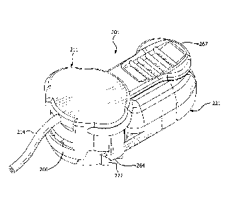
Accordingly, a need exists for an infusion set that incorporates a sensor to
measure blood
levels and facilitate insertion of the sensor.
CA 3043060 2019-05-13
3
[0009] Accordingly, a need exists for an infusion set that
facilitates insertion of the
cannula, while reducing the number of components a user must carry and
substantially
preventing accidental needle sticks.
SUMMARY OF THE INVENTION
[0010] An object of the present invention is to provide an exemplary
infusion set
that includes an integral introducer needle to facilitate cannula insertion.
[0011] Another object of the present invention is to provide an
infusion set having
a self-contained introducer needle to facilitate cannula insertion and reduce
the number of
components a user must carry.
[0012] Another object of the present invention is to provide an
infusion set in
which insertion of the catheter and introducer needle and retraction of the
introducer needle
is automatic, thereby substantially eliminating variability from the process.
[0013] Another object of the present invention is to provide an
infusion set having
a self-contained introducer needle to substantially reduce the overall size of
the infusion
set.
[0014] Another object of the present invention is to provide an
infusion set having
an integrated sensor, such as a blood glucose sensor.
[0015] Another object of the present invention is to provide an
infusion set in
which separate, self-contained introducer needles facilitate cannula and
sensor insertion.
[0016] In accordance with an exemplary embodiment of the present
invention, a
drug delivery infusion set houses and stores the introducer needle and the
means to insert
and retract the introducer needle. The catheter and introducer needle are self-
contained
within the body of the infusion set. The introducer needle is automatically
and fully
retracted with the self-contained inserter. Because the introducer needle is
self-contained
in the base of the infusion set, the user does not have to manually remove the
introducer
needle. Thus, user contact with the introducer needle is avoided, thereby
preventing
accidental introducer needle sticks.
[0017] In accordance with another exemplary embodiment of the present
invention,
a drug delivery infusion set houses and stores a cannula for drug delivery and
a sensing
element for continuously monitoring blood levels, both of which are self-
contained within
the body of the infusion set. The cannula and sensing element are both
substantially
simultaneously inserted in an injection site. The infusion set incorporates
the sensing
CA 30430602019-05-13
11
4
element therein, thereby reducing the amount of equipment a user needs to
carry as well as
reducing the number of procedures the user must perform.
[0018] These and other objects are substantially achieved
by providing an infusion
set having an integrated and self-contained inserter that inserts a catheter
and withdraws
the introducer needle of the infusion set, thereby reducing the number of
components
required to be carried by the user. Additionally, accidental introducer needle
sticks are
substantially prevented while providing a low profile infusion set.
BRIEF DESCRIPTION OF THE DRAWINGS
[0019] The above benefits and other advantages of the
various embodiments of the
present invention will be more apparent from the following detailed
description of
exemplary embodiments of the present invention and from the accompanying
drawing
figures, in which:
[0020] FIG. 1 is a perspective view of an assembled
infusion set in accordance with
a first exemplary embodiment of the present invention;
[0021] FIG. 2 is a top plan 'view in cross-section of the
infusion set of FIG. 1;
[0022] FIG. 3 is a partial perspective view of the
infusion set of FIG. 1;
[0023] FIG. 4 is a side perspective view in cross-section
of the infusion set of FIG.
I;
[0024] FIG. 5 is a partial top plan view of the infusion
set of FIG. 1;
[0025] FIG. 6 is a partial perspective view of the
infusion set of FIG. 1;
[0026] FIG. 7 is a partial perspective view of the
infusion set of FIG. 1;
[0027] FIG. 8 is a partial perspective view in cross-
section of the infusion set of
FIG. I;
[0028] FIG. 9 is a perspective view of an infusion set
according to a second
exemplary embodiment of the present invention;
[0029] FIG. 10 is a perspective view in cross-section of
the infusion set of FIG. 9;
[0030] FIG. 11 is a perspective view of the infusion set
of FIG. 9 with a locking
member removed;
[0031] FIG. 12 is a partial perspective view of the
infusion set of FIG. 9 with the
catheter and introducer hubs in first positions;
= [0032] FIG. 13 is a perspective view in cross-
section of the infusion set of FIG. 12;
CA 3043060 2019-05-13
5
[0033] FIG. 14 is a partial perspective view of the infusion set of
FIG. 9 with the
catheter and introducer hubs in second positions;
[0034] FIG. 15 is a perspective view in cross-section of the infusion
set of FIG. 14;
[0035] FIG. 16 is a partial perspective view of the infusion set of
FIG. 9 with the
catheter hub in the second position and the introducer hub returned to the
first position;
[0036] FIG. 17 is a perspective view in cross-section of the infusion
set of FIG. 16;
[0037] FIG. 18 is a perspective view of the infusion set of FIG. 9
with a connector
moved to a second position;
[0038] FIG. 19 is a perspective view of the infusion set of FIG. 18
with the
connector rotated prior to removal thereof;
[0039] FIG. 20 is a perspective view of the infusion set of FIG. 19
with the
connector removed from a base of the infusion set;
[0040] FIG. 21 is a perspective view in cross-section of the base of
the infusion set
showing first and second ends of a torsion spring;
[0041] FIG. 22 is a lower perspective view of the connector;
[0042] FIG. 23 is a perspective view of an infusion set with a
sensing element in
accordance with a third exemplary embodiment of the present invention;
[00431 FIG. 24 is a perspective view of the infusion set of FIG. 23
with a locking
member removed;
[0044] FIG. 25 is a bottom plan view of the infusion set of FIG. 23;
[0045] FIG. 26 is a partial top plan view of the infusion set of FIG.
23;
[0046] FIG. 27 is a partial perspective view of the infusion set of
FIG. 23;
[00471 FIG. 28 is an enlarged perspective view of a linking arm of
FIG. 27;
[0048] FIG. 29 is a partial perspective view in cross-section of the
infusion set of
FIG. 23 showing an introducer needle and catheter;
[0049] FIG. 30 is a partial perspective view in cross-section of the
infusion set of
FIG. 23 showing a drive and slave gear arrangement;
[0050] FIG. 31 is a partial perspective view in cross-section of the
infusion set of
FIG. 23 showing a fluid path;
[0051] FIG. 32 is another partial perspective view in cross-section
of the infusion
set of FIG. 31 showing a fluid path;
[0052] FIG. 33 is a perspective view of the infusion set of FIG. 23
showing
catheter and introducer hubs in a first position;
CA 3043060 2019-05-13
-- --
6
[0053] FIG. 34 is a perspective view of the infusion set
of FIG. 23 showing the
catheter hub in a second position and the introducer hub returned to the first
position;
[0054] FIG. 35 is a bottom plan view of the infusion set
of FIG. 23 with a cannula
and sensing element exposed;
[0055] FIG. 36 is partial a top plan of an infusion set
in accordance with a fourth
exemplary embodiment showing an infusion set having two sets of hubs; and
[0056] FIG. 37 is a partial perspective view of the
infusion set of FIG. 35;
[0057] FIG. 38 is a partial perspective view of the
infusion set of FIG. 35 showing
the hub set connected to a slave gear;
[0058] FIG. 39 is a partial perspective view of the
infusion set of FIG. 35 showing
an introducer hub in a second position and a sensing element hub slightly
withdrawn from
the second position; and
[0059] FIG. 40 is a partial top plan view of an infusion
set in accordance with a
fifth exemplary embodiment of the present invention.
[0060] Throughout the drawings, like reference numerals
will be understood to
refer to like parts, components and structures.
DETAILED DESCRIPTION OF THE EXEMPLARY EMBODIMENTS
[0061] The exemplary embodiments of the present invention
described below
provide a novel means of inserting a soft catheter into the skin. For example,
exemplary
embodiments of the present invention provide an integrated inserter that
inserts a soft
catheter into the skin and withdraws the introducer needle into a base of an
infusion set, as
shown in FIGS. 1 ¨ 8, while maintaining a low profile infusion set.
[0062] A base 121 of an infusion set 101, as shown in
FIG. 1, is preferably
provided with a skin-securing, adhesive layer (202 in FIG. 20) to secure the
infusion set to
the skin surface at a desired catheter insertion site. The adhesive layer
ensures that the
base is at the proper position relative to the skin surface, and that the skin
is secured during
insertion to further aid introducer needle insertion with a reduced risk of
tenting of the skin
surface. The base has a first recess 122 and a second recess (not shown)
adapted to receive
tabs of a fluid connector 111, thereby securing the fluid connector 111 to the
base 121 to
fully assemble the infusion set 101, as shown in FIG. I. A first ramped
surface 125 slopes
downwardly and outwardly toward the first recess 122, as shown in FIG. 6,
thereby
facilitating the connector tab to slide down into the first recess and
creating a snap-fit
l' CA 3043060 2019-05-13
7
connection. Ramped surfaces 126 slope outwardly at opposite ends of the first
recess 122,
as shown in FIG. 7, thereby allowing the fluid connector 111 to be rotated
with respect to
the base 121 to allow the connector tabs to be released from the base recesses
to disconnect
the connector 111 from the base 121.
[0063] An introducer hub 131 is movably disposed in the base 121 of
the infusion
set 101, as shown in FIG. 2. An upper portion 132 of the introducer hub 131
has an
opening 133 connected to a flexible introducer needle 134 rigidly connected to
a lower
portion 135 of the introducer hub 131, as shown in FIGS. 3 and 5. The upper
portion 132
of the introducer hub 131 is disposed between guide rails 123 and 124 of the
base 121, as
shown in FIGS. 5 and 6, to guide linear movement of the introducer hub 131.
The
introducer hub 131 is movable from a first position shown in FIG. 5, to a
second position
shown in FIG. 7, and back to the first position shown in FIG. 5. When the
introducer hub
131 is in the first position, the introducer needle 134 is disposed within the
base 121 as
shown in FIG. 4, thereby preventing any accidental introducer needle sticks.
When the
introducer hub 131 is in the second position, the introducer needle 134 is
exposed outside
of the base 121 as shown in FIG, 7 such that a patient's skin can be pierced
to insert an
angled catheter 142.
[0064] A catheter hub 141 abuts the lower portion 135 of the
introducer hub 131, as
shown in FIGS. 2 and 3. The flexible catheter 142 is rigidly connected to the
catheter hub
141. The introducer needle 134 is movably disposed within the catheter 142, as
shown in
FIG. 4, Linear movement of the introducer hub 131 results in linear movement
of the
catheter hub because of the engagement the lower portion 135 of the introducer
hub 131
and the catheter hub 141. The catheter hub 141 is movable between a first
position shown
in FIGS. 5 and 6, and a second position shown in FIG. 7. When the catheter hub
141 is in
the first position, the catheter 142 is disposed within the base 121. When the
catheter hub
141 is moved to the second position, the catheter 142 is moved out of the base
121 and is
insertable at an angle under the surface of a patient's skin.
[0065] A disc 171 is rotatably disposed in the base 121, as shown in
FIGS. 2 ¨ 8.
The disc 171 has an inner perimeter 172 forming an aperture therethrough and
an outer
perimeter 173. A torsion spring 181 is disposed within the inner perimeter 172
of the disc
171. Preferably, the torsion spring 181 is a 360 degree torsion spring, i.e.,
the torsion
spring causes the disc 171 to rotate 360 degrees upon release. First and
second recesses
174 and 175 are formed in the outer perimeter 173 of the disc 171. An opening
176 is
CA 3043060 2019-05-13
8
formed in an upper surface 177 of the disc, as shown in FIG. 4 and receives a
first
protrusion 152 of a linking arm 151.
[0066] The torsion spring 181 has a first end rigidly fixed to the
base 121. A
second end 183 of the torsion spring 181 is fixed to the disc 171, as shown in
FIGS. 2 and
3. An opening 184 can be formed in the disc 171 to receive the torsion spring.
[0067] The linking arm 151 connects the disc 171 to the introducer
hub 131,
thereby converting rotational movement of the disc 171 into linear movement of
the
introducer hub 131. The first protrusion 152 of the linking arm 151 extends
downwardly
proximal a first end 155 of the linking arm 151, as shown in FIGS. 3 and 4. A
second
protrusion 153 extends upwardly from a second end of the linking arm 151 and
is received
by an opening 137 in the introducer hub 131.
[0068] The button 161 is movable between a first, or up, position as
shown in FIG.
1, and a second, or lower, position as shown in FIG. 4. Tabs 162 and 163
extend inwardly
from free ends of arms 164 and 165 extending downwardly from an upper surface
166 of
the button, as shown in FIGS. 1 ¨ 3. When the button 161 is in the first
position, as shown
in FIGS. 1 and 2, the tabs 162 and 163 are received within the recesses 174
and 175 of the
disc 171, thereby preventing rotational movement of the disc 171. When the
button 161 is
pressed downwardly to the second position, as shown in FIG. 3, the tabs 162
and 163 are
moved downwardly below the disc 171 such that the tabs are no longer disposed
in the disc
recesses 174 and 175, thereby allowing the disc 171 to rotate due to the
torque applied by
the torsion spring.
[0069] Snap arms 167 and 168 extend downwardly from the button 161,
as shown
in FIGS. 2 and 6. Hooks disposed at the free ends of the snap arms 167 and 168
are
received in upper recesses (not shown) in the base 121, thereby maintaining
the button 161
in the up position shown in FIG. 1. When the catheter 142 is to be inserted,
the button 161
is pushed downwardly to the second position and the snap arms 167 and 168 move
from
the upper recesses to lower recesses (not shown) in the base 121. The snap
connection
between the button snap arms 167 and 168 and the lower recesses in the base
121
maintains the button 161 connected to the base 121 after inserting the
catheter 142.
[0070] An angled guide 191 is provided in the base 121 to guide
movement of the
introducer needle 134 and the catheter 142. The angled guide 191 creates an
angle with
respect to the surface of the skin of between approximately 30 and 45 degrees,
inclusive,
and preferably about 45 degrees. An opening 196 is formed in the base at the
end of the
CA 3043060 2019-05-13
9
angled guide 191 to allow the introducer needle 134 and catheter 142 to exit
the base. First
and second flexible arms 192 and 193 extend in the base 121 in the direction
of movement
of the catheter hub 141. Upwardly extending hooks 194 and 195 are disposed at
an end of
the flexible arms.
[0071] A septum 197 is disposed in an upper surface 127 of the base
121, as shown
in FIGS. 4 and 8. Preferably, the septum 197 has a slit 198 to facilitate
receiving a
penetrating member, or sharp, 199 of the connector 111, as shown in FIG. 4,
although the
slit may not be required in some cases. A groove 128 is formed in an upper
surface of the
introducer hub 131, as shown in FIG. 8, and having one end at the introducer
hub opening
133.
[0072] The fluid connector 111 has first and second flexible arms 112
and 113, as
shown in FIGS. 1 ¨ 3, that engage the first and second recesses 122 in the
base 121 to
secure the connector to the base. Tubing 114 extends from the fluid connector
111 and is
adapted to connect to a pump. The tubing 114 is connected to a penetrating
member 199
extending downwardly from the fluid connector 111, and a fluid path is formed
therebetween. The penetrating member 199 is adapted to penetrate the septum
197 when
the fluid connector Ill is connected to the base 121, as shown in FIG. 4.
[0073] Assembly and Operation
[0074] FIG. 1 is a perspective view of the infusion set 101 ready to
be inserted by a
user. The fluid connector 111 is secured to the base 121 by engaging the hooks
of arms
112 and 113 in the base recesses 122, as shown in FIGS. 1 and 3. Ramped
surfaces 125 in
the base 121 facilitate engaging the connector arms 112 and 113 with the base
recesses
122.
[0075] The button 161 is in the up, or first, position, as shown in
FIG. 1. In this
position, the button tabs 162 and 163 are disposed in the disc recesses 174
and 175, thereby
preventing rotation of the disc 171. The linking arm 151 is aligned with the
longitudinal
axis of the catheter 142, as shown in FIG. 2. The catheter hub 141 and the
introducer hub
131 are disposed to the right of the base 121 spaced from the hooks 194 and
195 of the
base flexible arms 192 and 193, as shown in FIGS. 2 and 3. The catheter 142
and the
introducer needle 134 are disposed within the base 121, thereby substantially
preventing
accidental introducer needle sticks.
[0076] Adhesive backing (not shown) is removed from the base 121 to
expose an
adhesive layer (202 in FIG. 20) on a lower surface of the base, such that the
base can be
CA 3043060 2019-05-13
to
firmly secured to a desired location on the skin. To insert the catheter 142,
the button 161
is pushed downwardly to a down, or second, position to release the torsion
spring 181,
thereby driving rotational movement of the disc 171. The downward movement of
the
button 161 moves the button tabs 162 and 163 out of the disc recesses 174 and
175,
thereby freeing the disc 171 to rotate. The button snap arms 167 and 168 move
from the
upper recesses to the lower recesses in the base 121, thereby securing the
button 161 to the
base 121. The second end 183 of the torsion spring 181 rotates with the disc
171.
[0077] As the disc 171 begins to rotate counter-clockwise as shown in
FIGS. 2, 3, 5
and 6, the linking arm 151 moves with the disc. The movement of the linking
arm 151, in
turn, results in linear movement of the introducer hub 131. The introducer hub
131 is
limited to linear movement by the guide rails 123 and 124, as shown in FIG. 5.
The linear
movement of the introducer hub 131 pushes the catheter hub 141 from a position
shown in
FIG. 6 to a position shown in FIG. 7. The introducer hub 131 pushes the
catheter hub 141
along the base flexible arms 192 and 193 such that the catheter hub 141 flexes
the arms
192 and 193 downwardly to pass over the hooks 194 and 195. After the catheter
hub 141
passes over the hooks 194 and 195, the hooks snap back up to prevent rearward
movement
of the catheter hub 141 back along the flexible arms 192 and 193. Stops 103
and 104
disposed in the base 121 prevent further forward linear movement by the
catheter hub 141.
Additionally, the forward linear movement of the catheter hub 141 and the
introducer hub
131 results in forward movement of the catheter 142 and the introducer needle
134,
respectively. The catheter 142 is fixedly attached to the catheter hub 141 and
the
introducer needle 134 is fixedly attached to the introducer hub 131. The
angled guide 191
in the base guides the downwardly angled movement of the catheter 142 and
introducer
needle 134. The introducer needle 134 extends beyond the catheter 142 such
that the
introducer needle pierces the surface of the skin to allow the catheter to be
inserted at an
angle beneath the surface of the skin. The disc 171 has rotated approximately
180 degrees
at this point.
[0078] As the disc 171 continues to rotate past the 180 degree point,
the linking
arm 151 causes the introducer hub 131 to move linearly rearwardly between the
guide rails
123 and 124. The hooks 194 and 195 of the base flexible arms 192 and 193
Prevent
rearward movement of the catheter hub 141. The rearward linear movement of the
introducer hub 131 pulls the introducer needle 134 out of the insertion site,
leaving the
catheter 142 inserted at an angle beneath the surface of the skin. As the disc
171 continues
CA 3043060 2019-05-13
11
to rotate to the 360 degree point, the introducer needle 134 is withdrawn
entirely into the
base 121 of the infusion set 101. The torsion spring 181 can be pre-loaded
such that the
disc 171 does not rotate more than approximately 360 degrees. Additionally, a
stop tab
(not shown) can be disposed in the base that mates with a corresponding stop
tab (not
shown) on the disc to prevent the disc from rotating more than approximately
360 degrees.
The infusion set 101 is now ready to begin infusing insulin.
[0079] A fluid path is created from the connector tubing 114, through
the septum
197, into the groove 128 of the introducer hub 131, through the opening 133 in
the
introducer hub 131, into the introducer needle 134 and into the catheter 142,
as shown in
FIGS. 4 and 8. The groove 128 is completely sealed by a lower surface 110 of
the septum
197, as shown in FIG. 8. Furthermore, the groove 128 is completely sealed by
the lower
surface 110 of the septum 197 over the entire range of motion of the
introducer hub 131,
thereby forming a dynamic seal.
[0080] The fluid connector 111 and tubing 114 can be easily removed
by rotating
the connector relative to the base 121. The hooks of the connector arms 112
and 113 slide
along the ramped surfaces 126 of the base recesses 122, allowing the connector
111 to be
easily disconnected from the base. The fluid connector 111 can then be
reconnected when
desired as described above.
[0081] The pre-loaded torsion spring 181, when released by the button
161,
performs both the insertion and retraction of the introducer needle 134.
Torsion springs
can store a large amount of energy within a small and flat profile. This is
facilitated by the
360 degree rotation of the disc 171 driven by the torsion spring 181. The
first 180 degree
rotation of the disc 171 inserts the introducer needle 134, and the second 180
degree
rotation of the disc retracts the introducer needle completely into the base
121. The torsion
spring 181 can be pre-loaded to not less than 180 degrees and up to
approximately 360
degrees to perform the insertion and retraction of the introducer needle.
[0082] The linking arm 151 between the introducer hub 131 and the
disc 171
produces a cyclical piston movement. By using a flexible or bending introducer
needle
134 and an angled catheter 142, the infusion set can have a low profile. The
angled guide
191 in the base 121 guides the introducer needle downwardly into the surface
of the skin.
Moreover, the only action required by the user to press the button 161
downwardly. The
insertion of the introducer needle 134 and the catheter 142 and retraction of
the introducer
needle occurs automatically. Additionally, by only requiring the user to push
the button
CA 3043060 2019-05-13
12
161 downwardly, the infusion set 101 can be positioned and used in hard to
reach and
awkward body locations.
[0083] The septum 197 is disposed approximately in the center of the
base 121,
thereby allowing multiple orientations when connecting the connector 111 to
the base 121.
The sliding septum design between the linearly moving introducer hub 131 and
the lower
portion 110 of the septum 197 allows for the septum to be centered on the base
121.
[0084] The exemplary embodiment described above can be adapted for
use with
either intradermal or subcutaneous injections. In
addition, a different method of
maintaining the fluid connection is possible other than through the
penetrating member 199
and septum 197. For example, a coiled tube connected to the introducer hub 131
that
extends during insertion of the introducer needle 134, and then recoils upon
retraction of
the introducer needle, can be used. Alternative methods may be used to insert
the catheter
and introducer needle. For example, an angled needle in contact with the skin
and driven
at a smaller angle can be used to enter the intradermal layer of the skin.
Alternative
methods of connecting the connector to the base can be used to facilitate
connecting and
disconnecting of the connector.
[0085] Although the exemplary embodiment described above is an
infusion set, it
will be apparent to those of ordinary skill in the art that the principles of
the present
invention are also applicable to patch pumps (self-contained infusion devices
with integral
reservoirs and pumping mechanisms) and other types of medical infusion and
injection
devices.
[0086] Second Exemplary Embodiment
[0087] An infusion set 201 in accordance with a second exemplary
embodiment of
the present invention is shown in FIGS. 9 ¨ 22. A base 221 of the infusion set
201, as
shown in FIG. 9, is preferably provided with a skin-securing, adhesive layer
202 (FIG. 20)
to secure the infusion set to the skin surface at a desired catheter insertion
site. The
adhesive layer ensures that the base 221 is at the proper position relative to
the skin
surface, and that the skin is secured during insertion to further aid
introducer needle
insertion with a reduced risk of tenting of the skin surface. The base has a
first recess 222
and a second recess (not shown) adapted to receive tabs of a fluid connector
211, thereby
securing the fluid connector 211 to the base 221 to fully assemble the
infusion set 201, as
shown in FIG. 9. A first ramped surface 225 (FIG. 20) slopes downwardly and
outwardly
toward the first recess 222, thereby facilitating the fluid connector tab to
slide down into
CA 3043060 2019-05-13
13
the first recess and creating a snap fit connection. A second ramped surface
226 (FIG. 20)
slopes outwardly at an end of the first recess 222, thereby allowing the fluid
connector 211
to be rotated with respect to the base 221 to allow the connector tabs to be
released from
the base recesses 222 to disconnect the fluid connector 211 from the base 221,
as shown in
FIG. 20.
[0088] An introducer hub 231 is movably disposed in the base 221 of
the infusion
set 201, as shown in FIG. 12. The introducer hub 231 has an opening 233 to
receive an
introducer needle 234, as shown in FIGS. 10 and 15. A lower portion 232 of the
introducer
hub 231 is disposed between guide rails 223 and 224 of the base 221, as shown
in FIG. 12,
to guide linear movement of the introducer hub 231. The introducer hub 231 is
movable
from a first position shown in FIG. 12, to a second position shown in FIG. 14,
and back to
the first position shown in FIG. 16. When the introducer hub 231 is in the
first position,
the introducer needle 234 is disposed within the base 221, thereby preventing
any
accidental introducer needle sticks. When the introducer hub 231 is in the
second position,
the introducer needle 234 is exposed outside of the base 221 such that a
patient's skin can
be pierced to insert an angled catheter 242.
[0089] A catheter hub 241 abuts the introducer hub 231, as shown in
FIGS. 12 ¨
15. The flexible catheter 242 is rigidly connected to the catheter hub 241.
The introducer
needle 234 is movably disposed within the catheter 242, as shown in FIGS. 10
and 15.
Linear movement of the introducer hub 231 results in linear movement of the
catheter hub
241 because of the engagement of the introducer hub 231 with the catheter hub
241. The
catheter hub 241 is movable between a first position shown in FIG. 12, and a
second
position shown in FIG. 14. When the catheter hub 241 is in the first position,
the catheter
242 is disposed within the base 221, as shown in FIG. 13. When the catheter
hub 241 is
moved to the second position, the catheter 242 is moved out of the base 221,
as shown in
FIG. 15, and is insertable at an angle under the surface of a patient's skin.
[0090] A disc 271 is rotatably disposed in the base 221, as shown in
FIGS. 10 and
12¨ 18. The disc 271 has an inner perimeter 272 forming an aperture
therethrough and an
outer perimeter 273, as shown in FIGS. 10, 12 and 14. A torsion spring 281 is
connected
to the disc 271. Preferably, the torsion spring 281 is a 360 degree torsion
spring, i.e., the
torsion spring 281 causes the disc 271 to rotate 360 degrees upon release.
First and second
recesses 274 and 275 are formed in the outer perimeter 273 of the disc 271, as
shown in
CA 3043060 2019-05-13
oo-t. a =
14
FIG. 14. An opening 276 is formed in an upper surface 277 of the disc, as
shown in FIG.
14 and receives a first end 252 of a linking arm 251.
[0091] The torsion spring 281 has a first end 282 rigidly fixed to
the base 221, as
shown in FIG. 21. A second end 283 of the torsion spring 281 is fixed to the
disc 271, as
shown in FIGS. 14 and 21. An opening 284 can be formed in the disc 271 to
receive the
second end 283 of the torsion spring 281.
[0092] The linking arm 251 connects the disc 271 to the introducer
hub 231,
thereby converting rotational movement of the disc 271 into linear movement of
the
introducer hub 231. The first end 252 of the linking arm 251 is connected to
the disc 271,
as shown in FIGS. 12 and 14 ¨ 16. A second end 253 of the linking arm 251 is
connected
to the introducer hub 231.
[0093] The fluid connector 211 is movable between a first, or up,
position as shown
in FIGS. 9, 10 and 13, and a second, or down, position as shown in FIGS. 15
and 17. The
fluid connector 211 is removably connected to the base 221 such that the fluid
connector
211 can be removed after the catheter 234 has been inserted, as shown in FIG.
20. Tabs
262 and 263 extend inwardly from free ends of arms 264 and 265 extending
downwardly
from an upper surface 266 of the connector 211, as shown in FIGS. 20 and 22.
When the
connector 211 is in the first position, as shown in FIGS. 9, 10 and 13, tabs
extending
downwardly from first and second locking ears 205 and 207 (FIG. 20) are
received within
the recesses 274 and 275 of the disc 271, thereby preventing rotational
movement of the
disc 271. When the connector 271 is pressed downwardly to the second position,
as shown
in FIGS. 15 and 17, a shoulder 203 (FIG. 22) of a downwardly extending post
209 of the
connector engages the upper surface of the septum assembly 297, thereby
pushing the
septum assembly 297 downwardly and disengaging the locking tabs on the septum
assembly 297 from recesses in the inner perimeter 272 of the disc 271. When
the tabs of
the septum assembly 297 are not received by the recesses in the inner
perimeter of the disc
271, the disc 271 can rotate due to the torque applied by the torsion spring
281.
[0094] Arms 264 and 265 extend downwardly from the connector 211, as
shown in
FIGS. 20 and 22. Tabs 262 and 263 disposed at the free ends of the arms 264
and 265 are
received on the ramps 225 of the base 221, thereby maintaining the connector
211 in the up
position shown in FIG. 9. When the catheter 242 is to be inserted, a locking
member 267
is removed such that the fluid connector 211 can be pushed downwardly to the
second
position. The downward movement of the fluid connector 211 flexes the arms 264
and 265
CA 3043060 2019-05-13
15
outwardly such that the arms 264 and 265 slide down the ramps 225 into the
recesses 222
in the base 221. The snap connection between the connector arms 264 and 265
and the
recesses 222 in the base 221 retains the fluid connector 221 connected to the
base 221 after
inserting the catheter 242.
[0095] An angled guide 291 is provided in the base 221 to guide
movement of the
introducer needle 234 and the catheter 242, as shown in FIGS. 10 and 12. The
angled
guide 291 creates an angle with respect to the surface of the skin of between
approximately
30 and 45 degrees, inclusive, and preferably about 45 degrees. An opening 296
is formed
in the base 221 at the end of the angled guide 291 to allow the introducer
needle 234 and
catheter 242 to exit the base 221. First and second flexible arms 292 and 293
extend in the
base 221 in the direction of movement of the catheter hub 241, as shown in
FIGS. 12, 14
and 16. Upwardly extending hooks 294 and 295 are disposed proximate an end of
each of
the flexible arms 292 and 293. Stop members 238 and 239 are disposed at the
ends of each
of the flexible arms 292 and 293, as shown in FIG. 12. Recesses 245 and 246
are formed
on each flexible arm 292 and 293 between the hooks 294 and 295 and the stop
members
238 and 239, respectively, to receive the catheter hub 241 in the second
position.
[0096] A septum 297 is disposed in the aperture formed in the disc
271, as shown
in FIG. 12. Preferably, the septum 297 has a slit to facilitate receiving a
penetrating
member, or sharp, of the fluid connector 211, as shown in FIG. 15, although
the slit may
not be required in some cases.
[0097] The fluid connector 211 has first and second flexible arms 264
and 265, as
shown in FIGS. 9, 11 and 22, that engage the first and second recesses 222 in
the base 221
to secure the fluid connector 211 to the base 221. Tubing 214 extends from the
connector
211 and is adapted to connect to a pump (not shown). The tubing 214 is
connected to a
penetrating member extending downwardly from the post 209 of the connector
211, and a
fluid path is formed therebetween. The penetrating member 299 is adapted to
penetrate the
septum 297 when the connector 211 is connected to the base 221, as shown in
FIGS. 10
and 15.
[0098] FIG. 9 is a perspective view of the infusion set 201 ready to
be inserted by a
user. A tab 206 on the base 221 is received by a recess 208 in the fluid
connector, as
shown in FIGS. 9 and 22, to prevent accidental removal of the fluid connector
211 from
the base 221 prior to an insertion procedure. The locking Member 267 is
disposed between
CA 3043060 2019-05-13
16
the base 221 and the connector 211 to prevent accidentally activating the
torsion spring
281 and exposing the needle 234 and catheter 242 prior to a desired insertion
procedure.
[0099] The fluid connector 211 is in the up, or first, position, as
shown in FIG. 9.
In this position, the locking tabs of the septum assembly 297 are disposed in
the recesses in
the inner perimeter 272 of the disc 271, thereby preventing rotation of the
disc 271. The
catheter hub 241 and the introducer hub 231 are disposed to the right of the
base 221
spaced from the hooks 294 and 295 of the base flexible arms 292 and 293, as
shown in
FIG. 12. The catheter 242 and the introducer needle 234 are disposed within
the base 221,
thereby substantially preventing accidental introducer needle sticks.
[00100] An adhesive backing (not shown) is removed from the base 221
to expose
an adhesive layer 202 (FIG. 20) on a lower surface of the base, such that the
base can be
firmly secured to a desired location on the skin. To insert the catheter 242,
the locking
member 267 is removed as shown in FIG. 11 such that the fluid connector 211
can be
pushed downwardly to a second, or down, position to release the torsion spring
281,
thereby driving rotational movement of the disc 271. The downward movement of
the
connector 211 causes the shoulder 203 of the connector post 209 to engage the
septum
assembly 297 and push the septum assembly 297 downwardly, thereby moving the
locking
tabs of the septum assembly 297 out of engagement with recesses in the inner
perimeter
272 of the disc 271, which frees the disc 271 to rotate. The connector arms
264 and 265
move from the ramp 225 to the recesses 222 in the base 221, thereby securing
the fluid
connector 211 to the base 221. The second end of the torsion spring 281
rotates with the
disc 271 as the torsion spring 281 causes the disc 271 to rotate.
[00101] As the disc 271 begins to rotate counter-clockwise as shown in
FIGS. 12, 14
and 16, the linking arm 251 moves with the disc 271. The movement of the
linking arm
251, in turn, results in linear movement of the introducer hub 231. The
introducer hub 231
is limited to linear movement by the guide rails 223 and 224, as shown in FIG.
12. The
linear movement of the introducer hub 231 pushes the catheter hub 241 from the
first
position shown in FIG. 12 to the second position shown in FIG. 14. The
introducer hub
231 pushes the catheter hub 241 along the base flexible arms 292 and 293 such
that the
catheter hub 241 flexes the arms 292 and 293 downwardly to pass over the hooks
294 and
295. After the catheter hub 241 passes over the hooks 294 and 295, the hooks
snap back
up to prevent rearward movement of the catheter hub 241 back along the
flexible arms 292
and 293. Stop members 238 and 239 disposed at ends of the arms 292 and 293
prevent
CA 3043060 2019-05-13
17
further forward linear movement by the catheter hub 241. Additionally, the
forward linear
movement of the catheter hub 241 and the introducer hub 231 results in forward
movement
of the catheter 242 and the introducer needle 234, respectively. The catheter
242 is fixedly
attached to the catheter hub 241 and the introducer needle 234 is fixedly
attached to the
introducer hub 231. The angled guide 291 in the base guides the downwardly
angled
movement of the catheter 242 and introducer needle 234. The introducer needle
234
extends beyond the catheter 242 such that the introducer needle 234 pierces
the surface of
the skin to allow the catheter 242 to be inserted at an angle beneath the
surface of the skin.
The catheter hub 241 is securely received between the hooks 294 and 295 and
the stop
members 238 and 239 to prevent rearward linear movement of the catheter hub
241 after
the catheter 242 has been inserted. The disc 271 has rotated approximately 180
degrees at
this point, as shown in FIG. 14.
[00102] As the disc 271 continues to rotate past the 180 degree point,
the linking
arm 251 causes the introducer hub 231 to move linearly rearwardly between the
guide rails
223 and 224. The hooks 294 and 295 of the base flexible arms 292 and 293
prevent
rearward movement of the catheter hub 241. The rearward linear movement of the
introducer hub 231 pulls the introducer needle 234 out of the insertion site,
leaving the
catheter 242 inserted at an angle beneath the surface of the skin, as shown in
FIG. 16. As
the disc 271 continues to rotate, the introducer needle 234 is withdrawn
entirely into the
base 221 of the infusion set 201. The torsion spring 281 can be pre-loaded
such that the
disc 271 does not rotate more than approximately 360 degrees. Additionally, a
stop tab
(not shown) can be disposed in the base that mates with a corresponding stop
tab (not
shown) on the disc 271 to prevent the disc from rotating more than
approximately 360
degrees. The infusion set 201 is now ready to begin infusing insulin.
[00103] A fluid path is created from the connector tubing 214, through
the septum
297, through the post 209, through the base tubing 228 fluidly connecting the
septum 297
and the introducer hub 231, through the introducer needle 234 and into the
catheter 242, as
shown in FIG. 17. The base tubing 228 is flexible such that the base tubing
228 moves
with the introducer hub 231 between first and second positions, as shown in
FIGS. 12, 14
and 16.
[00104] The connector 211 and tubing 214 can be easily removed by
rotating the
connector 211 relative to the base 221, as shown in FIGS. 19 and 20. The hooks
of the
connector arms 264 and 265 slide along the ramped surfaces 226 of the base
recesses 222
=
CA 30430602019-05-13
18
causing the arms 264 and 265 to flex outwardly, thereby allowing the connector
211 to be
easily disconnected from the base 221. The connector 211 can then be
reconnected when
desired as described above.
[00105] The pre-loaded torsion spring 281, when released by the
connector 211,
performs both the insertion and retraction of the introducer needle 234.
Torsion springs
can store a large amount of energy within a small and flat profile. This is
facilitated by the
360 degree rotation of the disc 271 driven by the torsion spring 281. The
first 180 degree
rotation of the disc 271 inserts the introducer needle 234, and the second 180
degree
rotation of the disc retracts the introducer needle completely into the base
221. The torsion
spring 281 can be pre-loaded to not less than 180 degrees and up to
approximately 360
degrees to perform the insertion and retraction of the introducer needle 234.
[00106] The linking arm 251 between the introducer hub 231 and the
disc 271
produces a cyclical piston movement. By using a flexible or bending introducer
needle
234 and an angled catheter 242, the infusion set 201 can have a low profile.
The angled
guide 291 in the base 221 guides the introducer needle 234 downwardly into the
surface of
the skin. Moreover, the only action required by the user is to press the
connector 211
downwardly. The insertion of the introducer needle 234 and the catheter 242
and the
retraction of the introducer needle occur automatically. Additionally, by only
requiring the
user to push the connector 211 downwardly, the infusion set 201 can be
positioned and
used in hard-to-reach and awkward body locations.
[00107] The exemplary embodiment described above can be adapted for
use with
either intradermal or subcutaneous injections. Alternative methods of
connecting the fluid
connector 211 to the base 221 can also be used to facilitate connecting and
disconnecting
of the fluid connector, such as a fluid connector connectable to a side of the
base 221.
[00108] Although the exemplary embodiment described above is an
infusion set, it
will be apparent to those of ordinary skill in the art that the principles of
the present
invention are also applicable to patch pumps (self-contained infusion devices
with integral
reservoirs and pumping mechanisms) and other types of medical infusion and
injection
devices.
[00109] Third Exemplary Embodiment
[00110] In accordance with a third exemplary embodiment of the present
invention
shown in FIGS. 23 - 35, an infusion set 301 includes an integral catheter 342
and blood
glucose sensing element 372. Suitable types of electromechanical sensing
elements are
CA 3043060 2019-05-13
-
19
disclosed in U.S. Patent Nos. 5,390471, 5,391,250, 5,482,473, and 5,586,553.
A pre-loaded torsion spring 381 inserts
the catheter 342 and the sensing element 372. By integrating the sensing
element 372 with
the infusion set 301, the amount of equipment required to be carried by a user
is reduced,
as well as reducing the number of procedures a user must perform. The torsion
spring 381
substantially simultaneously drives the insertion of two sharps, i.e., a
catheter introducer
needle 334 and the sensing element 372. The sensing element 372 can be a
glucose
oxidase sensor, a glucose binding protein sensor, or any other suitable
sensor, and can be
used either to allow intermittent user readings of blood glucose levels,
closed loop control
of infusion pump operation based on measured blood glucose levels (i.e.,
continuous
glucose monitoring), or both.
[001 1 1] As shown in FIG. 26, the infusion set 301 has a housing or
base 302 in
which a drive gear 303 and a slave gear 304 are disposed. The drive gear 303
inserts and
retracts the catheter introducer needle 334 and the catheter 342. The slave
gear 304 inserts
the sensing element 372. The catheter 342 and catheter introducer needle 334
are
preferably flexible. The sensing element 372 is preferably a flexible sharps.
1001121 The drive gear 303 is connected to the torsion spring 381. A
first end 382
of the torsion spring is connected to the housing 302 and a second end 383 of
the torsion
spring is connected to the drive gear 303, as shown in FIGS. 25 and 26.
Preferably, a
recess 384 in an upper surface 305 of the drive gear 303 receives the second
end 383 of the
torsion spring 381. A plurality of teeth 306 extend outwardly from an outer
perimeter of
the drive gear 303. Preferably, the plurality of teeth 306 extend continuously
around the
entire outer perimeter of the drive gear 303.
[00113] The slave gear 304 is disposed adjacent the drive gear 303 in
the housing
302 such that teeth 307 of the slave gear 304 engage the drive gear teeth 306,
as shown in
FIGS. 26 and 30. Preferably, the slave gear teeth 307 extend continuously on a
portion of
an outer perimeter of the slave gear 304. Preferably, the slave gear teeth 307
extend
approximately 180 degrees around the outer perimeter of the slave gear 304.
[00114] A catheter linking arm 351 has a first end 352 connected to
the drive gear
303 and a second end 353 connected to a catheter introducer hub 341, as shown
in FIGS.
26 - 29. Guide rails 354 and 355 in the housing 302 facilitate linear movement
of the
catheter introducer hub 341, as shown in FIG. 30.
CA 3043060 2019-05-13
20
[00115] A sensing element linking arm 361 has a first end 362
connected to the
slave gear 304 and a second end connected to a sensing element hub 371, as
shown in FIG.
26. The sensing element linking arm 361 is connected to the slave gear 304 in
a
substantially similar manner to the connection between the catheter linking
arm 351 and
the drive gear 303. The sensing element 372 is preferably a flexible sharp.
Guide rails 364
and 365 in the housing 302 facilitate linear movement of the sensing element
hub 371, as
shown in FIG. 30.
[00116] A locking member 391 has outwardly extending first and second
tabs 392
and 393, as shown in FIGS. 23 and 24. The locking tabs 392 and 393 pass
through
openings 308 and 309 in the housing 302 and are received by recesses 310 and
311 in the
drive and slave gears 303 and 304, respectively, as shown in FIG. 25. A
friction fit is
created between the locking tabs 392 and 393 and the openings 308 and 309 in
the housing
302. The locking tabs 392 and 393 prevent rotation of the drive and slave
gears 303 and
304 when the locking tabs 392 and 393 are received by the recesses 310 and 311
in the
drive and slave gears 303 and 304, respectively. Removing the locking member
391, as
shown in FIG. 24, disengages the tabs 392 and 393 from the drive and slave
gear recesses
310 and 311, thereby allowing the torsion spring 381 to rotate the drive and
slave gears 303
and 304.
[00117] An angled guide 395 is provided in the housing 302 to guide
movement of
the introducer needle 334 and the catheter 342, as shown in FIG. 29. The
angled guide 395
creates an angle with respect to the surface of the skin of between
approximately 30 and 45
degrees, inclusive, and preferably about 45 degrees. An opening 396 is formed
in the
housing 302 at the end of the angled guide 395 to allow the introducer needle
334 and
catheter 342 to exit the housing 302.
[00118] First and second flexible arms 385 and 386 extend in the
housing 302 in the
direction of movement of the catheter hub 331, as shown in FIGS. 26 and 27.
Upwardly
extending hooks 387 and 388 are disposed at an end of the flexible arms 385
and 386. A
substantially similar second angled guide 397 is disposed in the housing 302
to guide the
sensing element 372 through an opening 398. Preferably, the angled guides 395
and 397
are disposed at an angle a with respect to each other, as shown in FIGS. 26
and 35. The
angle a is preferably approximately 45 degrees to maximize the distance
between the point
of entry into the skin between the catheter 342 and the sensing element 372.
This
CA 3043060 2019-05-13
21
minimizes the direct effect of the insulin being administered on the measured
blood
glucose level.
[00119] A fluid connector 321 is removable connected to
the housing 302, as shown
in FIGS. 23 ¨25 and 35. Tubing 314 from the fluid connector 321 is connected
to a pump
(not shown) to supply medicament to the infusion set 301. A penetrating member
317 of
the fluid connector 321 pierces a septum 315 disposed in the housing 302 to
provide a fluid
path from the pump to the infusion set 301. Tabs 322 and 323 of the fluid
connector 321
are received by recesses 324 and 325 in the housing 302, as shown in FIGS. 25
and 26.
Finger grips 376 and 377 of the fluid connector 321 facilitate a user's grip
on the housing
302. The finger grips 376 and 377 can be squeezed together to unlock the tabs
322 and
323 from the housing recesses 324 and 325 to remove the fluid connector 321
from the
housing 302.
[00120] When the infusion set is ready to be used, an
adhesive backing (not shown)
is removed from the housing such that the housing can be disposed on the
user's body at a
desired location. Finger grips 376 and 377 connected to the housing 302
facilitate the
user's grip on the housing 302 while removing the locking member 391. The
locking
member 391 is removed from the housing 302, such that the locking tabs 392 and
393 are
disengaged from the recesses 310 and 311 in the drive and slave gears 303 and
304,
respectively. The drive and slave gears 303 and 304 are free to rotate after
the locking tabs
392 and 393 are removed from the recesses 310 and 311.
[00121] The torsion spring 381 causes the drive gear 303
to rotate when the locking
tabs 392 and 393 have been removed from the recesses 310 and 311. The
introducer hub
341 and catheter hub 331 are initially in a first position, as shown in FIG.
26, proximate the
drive gear 303. As the drive gear 303 rotates, the catheter linking arm 351
converts the
rotation of the drive gear 303 into linear movement of the catheter introducer
hub 341. The
catheter linking arm 351 moves the catheter introducer hub 341 linearly away
from the
drive gear 303, as shown in FIG. 23. The catheter introducer hub 341 pushes
the catheter
hub 331 as the catheter introducer hub 341 moves away from the drive gear 303.
The
guide rails 354 and 355 facilitate linear movement of the catheter introducer
hub 341 and
catheter hub 331, as shown in FIG. 30.
[00122] Rotation of the drive gear 303 rotates the slave
gear 304 due to the
engagement between the drive gear teeth 306 and the slave gear teeth 307. The
sensing
element linking arm 361 moves the sensing element hub 371 as the slave gear
304 is
r CA 30430602019-05-13
=
22
rotated by the drive gear 303. The guide rails 364 and 365 facilitate linear
movement of
the sensing element hub 371, as shown in FIG. 30.
[00123]
When the drive gear 303 has rotated approximately 180 degrees, the
introducer needle 334 and the catheter 342 have exited the housing 302 and are
inserted in
the skin in a substantially similar manner as in the first and second
exemplary
embodiments. Substantially simultaneously, the sensing element 372 has exited
the
housing 302 and is inserted in the skin in a substantially similar manner to
the introducer
needle 334.
[00124]
The torsion spring 381 continues to rotate the drive gear 303. The
linking
arm 351 moves the introducer hub 341 rearwardly, thereby withdrawing the
introducer
needle 334. The catheter hub 331 has passed over the hooks 387 and 388 at the
end of the
flexible arms 385 and 386 and is prevented from rearward movement by the hooks
387 and
388, as shown in FIGS. 33 and 34.
[00125]
After having rotated approximately 180 degrees, the slave gear teeth 307
are
not engaged with the drive gear teeth 306. Accordingly, the sensing element
linking arm
362 is not moved and the sensing element hub 371 is not moved such that the
sensing
element 372 remains inserted in the skin.
[00126]
Tubing 314 extends from the fluid connector 321 and is adapted to connect
to a pump. The tubing 314 is connected to the penetrating member 317 extending
from an
end of the tubing 314. The penetrating member 317 is adapted to penetrate the
septum 315
disposed in the housing 302, as shown in FIGS. 31 and 32. The septum 315 seals
a fluid
channel 318 disposed in the housing 302. A flexible base tubing 316 is
disposed at an
opposite end of the fluid channel 318 from the septum 315. An opposite end of
the flexible
base tubing 316 is connected to an opening 3 19 in the introducer hub 341. A
fluid path is
created from the connector tubing 314, through the septum 315, through the
fluid channel
318, through the base tubing 316 and into the introducer hub 341, through the
introducer
needle 334 and into the catheter 342, as shown in FIGS. 31 and 32. The base
tubing 316 is
flexible such that the base tubing 316 moves with the introducer hub 341
between first and
second positions, as shown in FIGS. 26, 33 and 34. The tubing 314 can be
removed from
the housing 302 by squeezing the finger grips together 376 and 377 to unlock
the tabs 322
and 323 from the housing recesses 324 and 325.
[00127]
The exemplary embodiment described above can be adapted for use with
either intraderrnal or subcutaneous injections.
In addition, a different method of
1 CA 3043060 2019-05-13
23
maintaining the fluid connection is possible other than using the tube 314,
such as a sliding
seal. Alternative methods can be used for connecting and disconnecting the
fluid
connector 321 to and from the housing 302, and for connecting and
disconnecting the
locking member 391 to and from the housing 302, such as a button or a dial.
[00128] Although the exemplary embodiment described above is an
infusion set, it
will be apparent to those of ordinary skill in the art that the principles of
the present
invention are also applicable to patch pumps (self-contained infusion devices
with integral
reservoirs and pumping mechanisms) and other types of medical infusion and
injection
devices.
[00129] Fourth Exemplary Embodiment
[00130] The fourth exemplary embodiment of an infusion set 401, as
shown in
FIGS. 36 ¨ 39, is substantially similar to the infusion set 301 of the third
exemplary
embodiment shown in FIGS. 23 ¨ 35. Similar components are identified with the
same
base number in the 400 series, e.g., 4xx. The sensing element 472 is inserted
by a sensing
element introducer needle in a similar manner as the catheter 342 of the third
exemplary
embodiment, instead of the sensing element itself being a sharps. The
remaining operation
and structure of the infusion set 401 is substantially similar to the infusion
set 301 of the
third exemplary embodiment.
[00131] A locking member 491 is received in the housing recesses such
that a
friction fit is created therebetween. When the infusion set 401 is ready to be
used,
adhesive backing is removed from the housing 402 such that the housing can be
disposed
on the user's body at a desired location. Finger grips 476 and 477 connected
to the
housing 402 facilitate the user's grip on the housing 402 while removing the
locking
member 491. The locking member 491 is removed from the housing 402, such that
the
locking tabs are disengaged from the recesses in the drive and slave gears 403
and 404,
respectively. The drive and slave gears 403 and 404 are free to rotate after
the locking tabs
are removed from the drive and slave gear recesses and from the openings in
the housing
402.
[00132] The torsion spring 481 causes the drive gear 403 to rotate
when the locking
tabs have been removed from the recesses in the drive and slave gears 403 and
404. The
introducer hub 441 and catheter hub 431 are initially in a first position, as
shown in FIGS.
36 and 37, proximate the drive gear 403. As the drive gear 403 rotates, the
catheter linking
arm 451 converts the rotation of the drive gear 403 into linear movement of
the catheter
CA 3043060 2019-05-13
24
introducer hub 441. The catheter linking arm 451 moves the catheter introducer
hub 441
linearly away from the drive gear 403. The catheter introducer hub 441 pushes
the catheter
hub 431 as the catheter introducer hub 441 moves away from the drive gear 403.
The
guide rails in the housing 402 facilitate linear movement of the catheter
introducer hub 441
and catheter hub 431.
[00133] Rotation of the drive gear 403 rotates the slave gear 404
due to the
engagement between the drive gear teeth 406 and the slave gear teeth 407. The
sensing
element linking arm 461 moves the sensing element introducer hub 493 as the
slave gear
404 is rotated by the drive gear 403. The sensing element introducer hub 493
pushes the
sensing element hub 471 as the sensing element introducer hub 493 moves away
from the
slave gear 404. The guide rails in the housing 402 facilitate linear movement
of the
sensing element introducer hub 493 and the sensing element hub 471.
[00134] When the drive gear 403 has rotated approximately 180
degrees, the
introducer needle and the catheter 442 have exited the housing 402 and are
inserted in the
skin in a substantially similar manner as in the first, second and third
exemplary
embodiments. Substantially simultaneously, the sensing element 472 has exited
the
housing 402 and is inserted in the skin in a substantially similar manner as
the introducer
needle.
[00135] The torsion spring 481 continues to rotate the drive gear
403. The linking
arm 451 moves the introducer hub 441 rearwardly, thereby withdrawing the
introducer
needle. The catheter hub 431 has passed over the hooks 487 and 488 at the end
of the
flexible arms 485 and 486 and is prevented from rearward movement by the hooks
487 and
488.
[00136] After having rotated approximately 180 degrees, the slave
gear teeth 407 are
still engaged with the drive gear teeth 406 as the slave gear teeth 407 extend
approximately
210 degrees around the outer perimeter of the slave gear 404, as shown in
FIGS. 36 and 37.
Accordingly, the slave gear 404 is rotated approximately 30 degrees, such that
the linking
arm 461 draws the sensing element introducer hub 493 rearwardly. The sensing
element
hub 471 is prevented from rearward movement by hooks 467 and 468 at the end of
flexible
arms 465 and 466, as shown in FIGS. 38 and 39. The rearward movement of the
sensing
element introducer hub 493 retracts the sensing element introducer needle,
thereby
exposing the sensing element (similar to the catheter being exposed in the
previous
exemplary embodiments). For example, the 30 degree rotation of the slave gear
404
¨ CA 3043060 2019-05-13
25
slightly retracts the sensing element introducer needle to expose the tip and
a small length
(e.g., approximately 2 mm) of the sensing element 472. Once the slave gear
teeth 407 are
no longer engaged with the drive gear teeth 406, as shown in FIG. 39, the
sensing element
introducer hub 493 is no longer moved rearwardly.
[00137] The exemplary embodiment described above can be adapted for
use with
either intradermal or subcutaneous injections. Although the exemplary
embodiment
described above is an infusion set, it will be apparent to those of ordinary
skill in the art
that the principles of the present invention are also applicable to patch
pumps (self-
contained infusion devices with integral reservoirs and pumping mechanisms)
and other
types of medical infusion and injection devices.
[00138] Fifth Exemplary Embodiment
[00139] The fifth exemplary embodiment of an infusion set 501, as
shown in FIG.
40, is substantially similar to the infusion sets 301 and 401 of the third and
fourth
exemplary embodiments shown in FIGS. 23 ¨ 39. Similar components are
identified with
the same base number in the 500 series, e.g., 5xx. The sensing element 572 is
inserted by a
sensing element introducer needle in a similar manner as in the fourth
exemplary
embodiment. Instead of using a slave gear, the sensing element introducer hub
593 and the
sensing element hub 571 are independently driven by a second torsion spring
582.
[00140] A first torsion spring 581 drives the catheter introducer hub
541 and the
catheter hub 531 as in the previous exemplary embodiments.
[00141] The second torsion spring 582 separately drives the sensing
element
introducer hub 593 and the sensing element hub 571 in a substantially similar
manner to
the first torsion spring 581.
[00142] The infusion set 501 preferably is packaged in a sterile
manner with an
infusion pump (not shown) already connected to the tubing 514. A locking
member 591 is
received in the housing recesses such that a friction fit is created
therebetween. When the
infusion set 501 is ready to be used, an adhesive backing (not shown) is
removed from the
housing 502 such that the housing can be disposed on the user's body at a
desired location.
Finger grips 576 and 577 connected to the housing 502 facilitate the user's
grip on the
housing 502 while removing the locking member 591. The locking member 591 is
removed from the housing 502, such that the locking tabs are disengaged from
the recesses
in the first and second drive discs 503 and 504, respectively. The first and
second drive
CA 3043060 2019-05-13
26
discs 503 and 504 are free to rotate after the locking tabs are removed from
the first and
second drive disc recesses and from the openings in the housing 502.
[00143] The second torsion spring 581 causes the second drive disc 505
to rotate
when the locking tabs have been removed from the recesses in the first and
second drive
discs 503 and 504. The sensing element introducer hub 593 and sensing element
hub 571
are initially in a first position, as shown in FIG. 40, proximate the second
drive disc 504.
As the second drive disc 504 rotates, the sensing element linking arm 561
converts the
rotation of the second drive disc 504 into linear movement of the sensing
element
introducer hub 593. The sensing element linking arm 561 moves the sensing
element
introducer hub 593 linearly away from the second drive disc 504. The sensing
element
introducer hub 593 pushes the sensing element hub 571 as the sensing element
introducer
hub 593 moves away from the second drive disc 504. The guide rails in the
housing 502
facilitate linear movement of the sensing element introducer hub 593 and the
sensing
element hub 571.
[00144] When the second drive disc 504 has rotated approximately 180
degrees, the
introducer needle and the sensing element 572 have exited the housing 502 and
are inserted
in the skin in a substantially similar manner as in the first, second, third
and fourth
exemplary embodiments. Substantially simultaneously, the catheter 542 and
catheter
introducer needle have exited the housing 502 and are inserted in the skin.
[00145] The second torsion spring 582 continues to rotate the second
drive disc 504.
The sensing element linking arm 561 moves the sensing element introducer hub
593
rearwardly, thereby withdrawing the sensing element introducer needle. The
sensing
element 572 remains inserted under the surface of the skin. The sensing
element hub 571
has passed over the hooks 567 and 568 at the end of the flexible arms 565 and
566 and is
prevented from rearward movement by the hooks 567 and 568.
[00146] The second torsion spring 582 can be set to a different
deflection ratio than
the first torsion spring 581. For example, the first torsion spring 581 can be
set for 180
degrees of travel, such that the first 90 degrees inserts the catheter
introducer needle and
catheter 542 and the second 90 degrees retracts the catheter introducer needle
into the
housing 502. The second torsion spring 582 can be set for 120 degrees of
travel. The first
90 degrees inserts the sensing element introducer needle and sensing element
572. The
remaining 30 degrees of travel slightly retracts the sensing element
introducer needle to
expose the tip and a small length (e.g., approximately 2 mm) of the sensing
element 572.
CA 3043060 2019-05-13
27
=
[00147] The exemplary embodiment described above can be adapted for
use with
either intradermal or subcutaneous injections. Although the exemplary
embodiment
described above is an infusion set, it will be apparent to those of ordinary
skill in the art
that the principles of the present invention are also applicable to patch
pumps (self-
contained infusion devices with integral reservoirs and pumping mechanisms)
and other
types of medical infusion and injection devices.
[00148] The foregoing embodiments and advantages are merely exemplary
and are
not to be construed as limiting the scope of the present invention. The
description of
exemplary embodiments of the present invention is intended to be illustrative,
and not to
limit the scope of the present invention. Various modifications, alternatives
and variations
= will be apparent to those of ordinary skill in the art, and are intended
to fall within the
scope of the appended claims and their equivalents.
CA 3043060 2019-05-13