Language selection

Search

Patent 3043128 Summary

Third-party information liability

Some of the information on this Web page has been provided by external sources. The Government of Canada is not responsible for the accuracy, reliability or currency of the information supplied by external sources. Users wishing to rely upon this information should consult directly with the source of the information. Content provided by external sources is not subject to official languages, privacy and accessibility requirements.

Claims and Abstract availability

Any discrepancies in the text and image of the Claims and Abstract are due to differing posting times. Text of the Claims and Abstract are posted:

  • At the time the application is open to public inspection;
  • At the time of issue of the patent (grant).
(12) Patent Application: (11) CA 3043128
(54) English Title: SCREWDRIVER AND SCREW FOR A SURGICAL APPLICATION
(54) French Title: TOURNEVIS ET VIS POUR UNE APPLICATION CHIRURGICALE
Status: Examination
Bibliographic Data
(51) International Patent Classification (IPC):
  • A61C 08/00 (2006.01)
  • A61B 17/86 (2006.01)
  • A61B 17/88 (2006.01)
(72) Inventors :
  • HORNBECK, JACQUES (Luxembourg)
(73) Owners :
  • JADE FINANCE S.A.R.L.
(71) Applicants :
  • JADE FINANCE S.A.R.L. (Luxembourg)
(74) Agent: GOWLING WLG (CANADA) LLP
(74) Associate agent:
(45) Issued:
(86) PCT Filing Date: 2017-11-15
(87) Open to Public Inspection: 2018-05-24
Examination requested: 2022-09-12
Availability of licence: N/A
Dedicated to the Public: N/A
(25) Language of filing: English

Patent Cooperation Treaty (PCT): Yes
(86) PCT Filing Number: PCT/EP2017/079296
(87) International Publication Number: EP2017079296
(85) National Entry: 2019-05-07

(30) Application Priority Data:
Application No. Country/Territory Date
93307 (Luxembourg) 2016-11-15

Abstracts

English Abstract

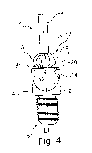
The invention comprises a combination (1, 101) of a screw (4, 104) for a surgical application, and a driver (2, 102) for driving the screw (4, 104) for fastening orthopaedic Implants either to bone or to an orthopaedic implant in particular a dental component to a dental implant is proposed, the screw (4, 104) having a first end (3) and an apical end (5), a head (10) at its first end (3) and a thread (13) at its apical end (5), a bore (12, 112) running axially from the first end (3) of the screw along a portion of the screw (4, 104) towards the apical end (5) of the screw (4, 104), a first zone (7, 107) at the first end (3) of the bore (12, 112) and a second zone (9, 109) at the apical end of the bore (12, 112), the first zone (7, 107) of the bore (12, 112) comprises clipping means (20, 120) and the second zone of the bore comprises peripheral engagement means (14, 114); the driver (2, 102) comprises a driver head (6, 106) having a first (16, 116) and a second segment (17, 117), the first segment (16, 116) comprises means (19) for triggering the clipping means (20, 120) in the first zone (7, 107) of the bore (12, 112) during the axial insertion of the driver head (6, 106) into the bore (12, 112) so as to maintain the screw (4, 104) releasably fastened to the driver (2, 102); the second segment (17, 117) comprises means for engaging the peripheral engagement means (14, 114) in the second zone (9, 109) at the apical end of the bore (12, 112) for the transmission of a couple to fasten or loosen the screw (4, 104), wherein the second segment (17, 117) of the driver head (6, 106) has a substantially rounded axial section, and the second zone (9, 109) of the bore (12, 112) has a rounded socket shape adapted to engage with the second segment (17, 117) of the driver head (6, 106) in various angled positions of the driver (2, 102) versus the axial direction of the screw (4, 104).


French Abstract

L'invention comprend une combinaison (1, 101) d'une vis (4, 104) pour une application chirurgicale, et un élément d'entrainement (2, 102) pour entraîner la vis (4, 104) pour fixer des implants orthopédiques soit à un os, soit à un implant orthopédique, en particulier un composant dentaire à un implant dentaire, la vis (4, 104) ayant une première extrémité (3) et une extrémité apicale (5), une tête (10) au niveau de sa première extrémité (3) et un filetage (13) au niveau de son extrémité apicale (5), un alésage (12, 112) s'étendant axialement depuis la première extrémité (3) de la vis le long d'une partie de la vis (4, 104) vers l'extrémité apicale (5) de la vis (4, 104), une première zone (7, 107) au niveau de la première extrémité (3) de l'alésage (12, 112) et une seconde zone (9, 109) au niveau de l'extrémité apicale de l'alésage (12, 112), la première zone (7, 107) de l'alésage (12, 112) comprend des moyens de clipsage (20, 120) et la deuxième zone de l'alésage comprend des moyens de mise en prise périphériques (14, 114); l'élément d'entrainement (2, 102) comprend une tête d'entraînement (6, 106) ayant un premier segment (16, 116) et un second segment (17, 117), le premier segment (16, 116) comprenant des moyens (19) pour déclencher le moyen de clipsage (20, 120) dans la première zone (7, 107) de l'alésage (12, 112) lors de l'insertion axiale de la tête d'entraînement (6, 106) dans l'alésage (12, 112) de manière à maintenir la vis (4, 104) fixé de manière amovible à l'élément d'entrainement (2, 102); le second segment (17, 117) comprend des moyens pour venir en prise avec les moyens de mise en prise périphériques (14, 114) dans la seconde zone (9, 109) au niveau de l'extrémité apicale de l'alésage (12, 112) pour la transmission d'un couple pour fixer ou desserrer la vis (4, 104), le deuxième segment (17, 117) de la tête d'entraînement (6, 106) présentant une section axiale sensiblement arrondie, et la deuxième zone (9, 109) de l'alésage (12, 112) a une forme de douille arrondie conçue pour venir en prise avec le second segment (17, 117) de la tête d'entraînement (6, 106) dans diverses positions angulaires de l'élément d'entrainement (2, 102) par rapport à la direction axiale de la vis (4, 104).

Claims

Note: Claims are shown in the official language in which they were submitted.


18
Claims
1. A combination (1, 101) of a screw (4, 104) for a surgical application, and
a
driver (2, 102) for driving the screw (4, 104) for fastening an orthopaedic
implant either to a bone or to an orthopaedic implant, in particular a dental
component to a dental implant,
the screw (4, 104) having a first end (3) and an apical end (5), a head (10)
at
its first end (3) and a thread (13) at its apical end (5),
a bore (12, 112) running axially from the first end (3) of the screw (4, 104)
along a portion of the screw (4, 104) towards the apical end (5) of the screw
(4, 104),
a first zone (7, 107) at the first end of the bore (12, 112) and a second zone
(9, 109) at the apical end of the bore (12),
the first zone (7, 107) of the bore (12, 112) comprises clipping means (20,
120) and the second zone (9, 109) of the bore (12, 112) comprises peripheral
engagement means (14, 114),
the driver (2, 102) comprises a driver head (6, 106) having a first (16, 116)
and a second segment (17, 117),
the first segment (16, 116) comprises means (19) for triggering the clipping
means (20, 120) in the first zone (7, 107) of the bore (12, 112) during the
axial insertion of the driver head (6, 106) into the bore (12, 112) so as to
maintain the screw (4, 104) releasably fastened to the driver (2, 102),
the second segment (17, 117) comprises means for engaging the peripheral
engagement means (14, 114) in the second zone (9, 109) at the apical end of
the bore (12, 112) for the transmission of a couple to fasten or loosen the
screw (4, 104),
wherein the second segment (17, 117) of the driver head (6, 106) has a
substantially rounded axial section, and the second zone (9, 109) of the bore
(12, 112) has a rounded socket shape adapted to engage with the second
segment (17, 117) of the driver head (6, 106) in various angled positions of
the driver (2, 102) versus the axial direction of the screw (4, 104).

19
2. The combination according to claim 1, characterised in that there is a gap
between the driver head (6, 106) and the bore (12, 112) in the second zone
(9, 109).
3. The combination according to anyone of claim 1 and 2, characterised in that
the clipping means (20, 120) are regularly spaced on the circumference of
the first zone (7, 107) of the bore (12, 112).
4. The combination according to anyone of claim 1 and 2, characterised in that
the head (10) comprises a peripheral wall (18) around the bore (12, 112),
the clipping means (20, 120) comprising a clipping portion (24) on the
peripheral wall (18) that is able to deform radially and elastically.
5. The combination according to anyone of the preceding claims,
characterised in that the head (10) comprises a peripheral wall (18) around
the bore (12, 112), the clipping means (20, 120) comprising a clipping
portion (24) of the peripheral wall (18) that extends in the axial direction
from the first end of the head (10) until one deformation point / location /
zone, the clipping portion (24) being able to clip-out with outwardly radially
oriented forces and to clip / snap back-in, by spring effect.
6. The combination according to anyone of the preceding claims,
characterised in that the second segment (17, 117) of the driver head (6,
106) has a diameter that is reducing with the increasing distance to the tip,
and presents a first (50, 150) and a second (52, 152) linear or curved sub-
portion, proximal and distal to the tip of the driver (2, 102), respectively,
the
peripheral engagement means (14, 114) being arranged in the second zone
(9, 109) of the bore (12, 112) in order to cooperate with the second (52,
152), distal, linear or curved sub-portion and the first (50, 150), proximal,
linear or curved sub-portion, when the driver (2, 102) is in the axial
direction
and is angled versus the axial direction, respectively.
7. The combination according to claim 6, characterised in that the curved sub-
portions (150, 152) are curved with opposite convexities and present an
axial profile with a form of an "S".

20
8. The combination according to claim 6 or 7, characterised in that the second
zone (9, 109) comprises a spherical surface (44, 144) extending from the
apical end of the bore (12, 112) until the peripheral engagement means (14,
114), the first segment (16, 116) of the driver head (6, 106) comprising a
peripheral surface able to abut against said spherical surface (44, 144)
when the driver (2, 102) is in the axial direction or angled versus the axial
direction.
9. The combination according to anyone of the preceding claims,
characterised in that the clipping means (20, 120) comprise clipping
protrusions (26, 126) uniformly spaced in the periphery of the bore (12, 112)
with inwardly radially oriented apices (28, 128) forming a circumferential
interface apices line between the first zone (7, 107) and the second zone (9,
109) of the bore (12, 112).
10. The combination according to claim 9, characterised in that the clipping
protrusions (26, 126) comprise contact surfaces (34, 134) starting from the
apices (28, 128) and extending radially outwardly towards the first end of
the bore (12, 112), the contact surfaces (34, 134) being intended to be
pressed in the axial direction by the first segment (16, 116) of the driver
head (6, 106) at introduction of the driver (2, 102) in order to bend radially
and outwardly.
11. The combination according to claim 10, characterised in that the first
zone
(7, 107) of the bore (12, 112) forms a conical surface around the axis of the
screw, and comprises the contact surfaces (34, 134).
12. The combination according to anyone of claims 9 to 11, characterised in
that the clipping protrusions (26, 126) comprise securing surfaces (38, 138)
starting from the apices (28, 128) and extending radially outwardly towards
the apical end of the bore (12, 112), the second segment (17, 117) of the
driver head (6, 106) forming a generally outwardly curved axial profile
toward the tip of the driver (2, 102) configured to abut said securing
surfaces.

21
13. The combination according to anyone of claims 10 to 12, characterised in
that the contact surfaces (34, 134) and/or the securing surfaces (38, 138)
are inclined with regard to the axial direction of the screw in an angle
between 10° and 80°, preferably between 20° and
40°.
14. The combination according to anyone of the preceding claims,
characterised in that the peripheral engagement means (14, 114) comprise
a peripheral engagement surface in the second zone (9, 109) of the bore
(12, 112) forming a multilobular transversal profile, preferably a
pentalobular
profile, the protruding zones of the multilobular profile comprising the
securing surfaces (38, 138) of the clipping protrusions (26, 126).
15. The combination according to anyone of the preceding claims,
characterised in that the screw (4, 104) is made of Titanium alloy.
16. The combination according to anyone of the preceding claims,
characterised in that the driver (2, 102) comprises a shaft (8) linked to the
driver head (6, 106) and the shaft (8) has a diameter that is between 40%
and 50% of the maximum diameter of the driver head (6, 106).
17. A process of operation of a combination (1) according to anyone of the
preceding claims, the process of operation comprising the steps:
a) alignment of the driver (2, 102) with the axial direction of the screw
(4, 104);
b) contact of the first segment (16, 116) of the driver head (6, 106) with
the clipping means (20, 120) of the screw (4, 104);
c) axial pressure exercised by the first segment (16, 116) of the driver
head (6, 106) on the clipping means (20, 120) for triggering the
clipping mechanism of said clipping means (20, 120);
d) axial penetration of the driver head (6, 106) from the first zone (7,
107) to the second zone (9, 109) of the bore (12, 112);
e) rotation of the driver (2, 102) for engaging the second segment (17,
117) of the driver head (6, 106) with the peripheral engagement
means (14, 114) in the bore (12, 112) for couple transmission.

Description

Note: Descriptions are shown in the official language in which they were submitted.


CA 03043128 2019-05-07
WO 2018/091515 PCT/EP2017/079296
1
Screwdriver and Screw for a surgical application
FIELD OF THE INVENTION
[0001] The present invention generally relates to the field of surgical
implants
and in particular for dental prostheses fixation. The invention relates to a
combination of a screwdriver and a screw for fastening orthopaedic Implants
either to bone or to an orthopaedic implant, in particular to a dental
component
to a dental implant fixing dental implant fixation. It also relates to a
process of
operation of the combination.
BACKGROUND OF THE INVENTION
[0002] It is known to use screws to fix an artificial denture to an implant in
the
jaw-bone. The artificial dentures generally comprise a tooth crown or a bridge
with two or more artificial teeth, where the tooth crown or the bridge is
connected to the dental implant by one or more screws. A screwdriver is used
to screw or unscrew such a screw in the implant. There is a risk however that
the screw while manoeuvring in the mouth of the patient falls into the mouth
of
the patient and be swallowed or breathed in.
[0003] WO 2013/004386 Al discloses a combination of a screw for a dental
application and a driver for driving the screw for fastening a dental
component
to a dental implant, the screw having a coronal end and an apical end and
comprising : a bore running from the coronal end of the screw along a portion
of
the screw towards the apical end of the screw, a first number of equally
spaced
recesses arranged circumferentially around an inside surface of the bore, each
recess running a length from the coronal end of the bore towards the apical
end
of the bore and being connected to flat engagement surfaces. The recesses
and the engagement surfaces are angled relative to the axial direction of the
screw so that they form a bore with a section that is reducing with an
increasing
distance to the coronal end of the bore.
[0004] The driver comprises a driver head which presents a polygonal
transversal section able to engage with the engagement surfaces of the bore.

CA 03043128 2019-05-07
WO 2018/091515 PCT/EP2017/079296
2
The driver head comprises a first portion at distance from the tip of the
driver
head that has a rounded cross section configured to engage with the
engagement surface for the couple transmission on the screw. The pressure
exercised by the driver in the bore creates a friction between the first
portion of
the driver head and the engagement surfaces in the bore, so that the screw can
be held by the driver head. The solution is interesting because the
combination
allows a carry function of the screw; it also allows a couple transmission
operation with an inclination of the driver with regard to the axial direction
of the
screw. However, the carry function is not very effective as a slight change of
angular orientation of the driver head in the bore may release the screw.
Furthermore the carry function may weaken over time/use since the friction
forces may diminish when the screw is set on the screwdriver repeatedly.
[0005] DE 10 2009 015358 Al discloses a screw comprising a screw head and
a screw shaft, wherein the screw shaft comprises a chamber for receiving a
.. wrench. The chamber is conical and comprises a plurality of first guiding
surfaces as well as a plurality of second guiding surfaces, which are undercut
with respect to the first guiding surfaces. These guiding surfaces correspond
to
guiding surfaces of the wrench. Between the first and second guiding surfaces,
there are force transfer surfaces for cooperating with corresponding force
transfer surfaces of the wrench.
[0006] DE 20 2009 009500 U1 discloses a screw profile for use in connection
with dental implants. The profile comprises a screw head with a chamber for
receiving a tool head of an assembly tool, and a screw shaft. Within the
chamber, there is a groove or a ridge for cooperating with a corresponding
ridge
or groove of the tool head in order to latchingly connect the screw head with
the
assembly tool. The only embodiment shows a hexagon socket head screw and
a corresponding hexagon socket head wrench.
[0007] EP 2 420 354 Al discloses a coupling tool for use with a screw head.
The tool comprises a rod having at one end a truncated cone-like surface and a
protuberance having at one end a base portion located adjacent said surface
and at the other end a pole. The protuberance has a plurality of meridional

CA 03043128 2019-05-07
WO 2018/091515 PCT/EP2017/079296
3
grooves having a curved concave transverse section, separated from one
another by spherical lunes having a curved convex external surface. The screw
head has a recess and axial projections which cooperate with the meridional
grooves.
OBJECT OF THE INVENTION
[0008] The object of the present invention is to provide a solution which
overcomes the disadvantages of the prior art, in particular of the prior art
cited
above. More particularly, the object of the present invention is to provide a
solution of a combination of a driver and a screw that improves the carry
function of the screw by the driver.
SUMMARY OF THE INVENTION
[0009] According to the present invention, a combination of a screw for a
surgical application, and a driver for driving the screw for fastening
orthopaedic
Implants either to bone or to an orthopaedic implant in particular a dental
component to a dental implant is proposed, the screw having a first end and an
apical end, a head at its first end and a thread at its apical end, a bore
running
axially from the first end of the screw along a portion of the screw towards
the
apical end of the screw, a first zone at the first end of the bore and a
second
zone at the apical end of the bore, the first zone of the bore comprises
clipping
means and the second zone of the bore comprises peripheral engagement
means; the driver comprises a driver head having a first and a second segment,
the first segment comprises means for triggering the clipping means in the
first
zone of the bore during the axial insertion of the driver head into the bore
so as
to maintain the screw releasably fastened to the driver; the second segment
comprises means for engaging the peripheral engagement means in the second
zone at the apical end of the bore for the transmission of a couple to fasten
or
loosen the screw; the second segment of the driver head has a substantially
rounded axial section, and the second zone of the bore has a rounded socket
shape adapted to engage with the second segment of the driver head in various
angled positions of the driver versus the axial direction of the screw.

CA 03043128 2019-05-07
WO 2018/091515 PCT/EP2017/079296
4
[0010] The merit of the invention is to provide a solution where the screw is
safely and temporarily fastened / secured to the driver so that the dentist
can
manoeuvre the screw fastened on the screwdriver inside the mouth of the
patient without risking losing the screw. The fastening mechanism works
reliably
when the screw is to be fixed on the dental implant but also when the screw is
to be removed from the dental implant. Indeed, the clipping means in the first
zone of the bore allow the screw to be securely held by the first segment of
the
driver head. The second segment of the driver head engages with the
engagement means of the bore that are situated in the second zone of the bore
for couple transmission i.e. to screw or unscrew the screw into or out of the
implant.
[0011] The clipping means not only allow to securely holding / maintaining /
retaining the screw on the tip of the screwdriver but they also give a
feedback to
the operator that the screw is firmly engaged / secured / clipped on the
screwdriver. The operator can indeed feel and/or hear when the clipping means
is triggered. It takes a certain force to trigger the clipping means, to
overcome
the resistance since the clipping means are "pushed aside" when the head of
the screwdriver engages the bore of the screw. The clipping means snap back
in their original position after the head of the screwdriver is inserted in
the bore
and thus maintains the screw on the driver head. The clipping means thus
involve an elastic deformation of the walls surrounding the bore of the screw.
This force is such that the screw can easily be pushed onto the driver by two
fingers and can also be released by excreting a pull on the screwdriver by to
fingers. This force is estimated at about 2 Newton +/ 0.5 Newton.
[0012] There may be a gap between the driver head and the second zone in
the bore so that the driver head is not jammed / stuck in the second zone of
the
bore while the screw is secured in position on the driver head. This allows
changing the orientation of the driver, i.e. to tilt the driver relative to
the axis of
the screw when rotating the screw for couple transmission.
[0013] The poor holding performance of the screw disclosed in
WO 2013/004386 Al is due to the fact that the screw is fastened to the driver

CA 03043128 2019-05-07
WO 2018/091515 PCT/EP2017/079296
only through friction forces, which are created by the fact that the
engagement
means are angled relative to the axial direction of the screw so as to form a
bore with a tapered section i.e. that is reducing with an increasing distance
to
the first end of the bore. The engagement means of the bore are used as
5 friction surfaces to maintain the screw on the screwdriver. This is
however
unreliable since the friction forces may be different when the screw /
screwdriver are wet or dry. The friction forces differ also with each screw or
with
each screw / screwdriver combination. Finally the user gets no feedback as to
when the screw is securely fastened to the screwdriver. Furthermore, when
repeatedly used, the friction forces may diminish.
[0014] In a preferred embodiment, the clipping means are regularly spaced
around the circumference of the first zone of the bore.
[0015] Advantageously, the head of the screw has an external profile which is
circular. The external diameter of the head of the screw can be between 1.5mm
and 3mm.
[0016] In a preferred embodiment, the engagement means can form a
mutlilobular transversal profile, preferably a pentalobular profile.
Alternatively,
the engagement means can form a TorxTm profile. The engagement means are
thus not angled relative to the axial direction of the screw as in in
WO 2013/004386 Al.
[0017] The head comprises a peripheral wall around the bore. In a preferred
embodiment, the clipping means comprise a portion of the peripheral wall that
is
able to be deformed radially and elastically. When the screwdriver head is
inserted into the bore of the screw, the clipping portion is pushed outward
due
to the outwardly radially oriented forces and the clipping means pivot
radially
outwardly and to clip back-in, by a spring effect, by pivoting radially
inwardly. At
the pivot zone, the minimum thickness of the peripheral wall is between 0.1mm
and 0.5mm.
[0018] The peripheral wall at the level of the clipping means has a thickness
of
less than 0.1mm.

CA 03043128 2019-05-07
WO 2018/091515 PCT/EP2017/079296
6
[0019] The peripheral wall at the level of the clipping means has a thickness
of
more than 0.5mm so as to guarantee a minimal stability of the screw head.
[0020] In a preferred embodiment, the pivot zone extends around the entire
circumference of the bore and is preferably situated at about half of the
depth of
the bore. The depth of the bore can be between 0.8mm and 1.5mm.
[0021] As mentioned above, the second segment of the driver head has a
substantially rounded axial section, and the second zone of the bore has a
rounded socket shape adapted to cooperate with the second segment of the
driver head in various angled positions of the driver with regard to the
length of
the screw ¨ i.e. from the first end to the apical end of the screw.
[0022] In a preferred embodiment, the second segment has a diameter that is
reducing with the increasing distance to the tip of the screwdriver. It
presents a
first and second linear or curved sub-portion, proximal and distal to the tip
of the
driver, respectively. The peripheral engagement means are arranged in the
.. second zone of the bore so as to cooperate with the second, distal, linear
or
curved sub-portion and the first, proximal, linear or curved sub-portion, when
the driver is in the axial direction and is angled versus the axial direction,
respectively.
[0023] In a preferred embodiment, the curved sub-portions are curved with
opposite convexities and present an axial profile with a form of an "S".
[0024] In a preferred embodiment, the second zone at the apical end of the
bore comprises a spherical surface extending from the apical end of the bore
to
the peripheral engagement means, the first segment of the driver head
comprising a peripheral surface able to abut against said spherical surface
when the driver head is inserted in the screw and is in the axial direction or
angled relative to the axial direction. Advantageously, the first segment of
the
driver head extends substantially transversally.
[0025] In a preferred embodiment, the clipping means comprise clipping
protrusions which are preferably uniformly spaced around the periphery of the
bore. The clipping protrusions may comprise radially inwardly oriented apices
forming a circumferential interface apice line between the first zone and the

CA 03043128 2019-05-07
WO 2018/091515 PCT/EP2017/079296
7
second zone of the bore. The ratio between the diameter formed by the
circumferential interface apice line and the diameter of the external profile
of the
head of the screw is between 0.6 and 0.8. The minimum diameter is preferably
1.3 mm and the maximum diameter is preferably 1.75 mm.
[0026] In a preferred embodiment, the clipping protrusions comprise a contact
surface starting from the apices and extending radially outwardly towards the
first end of the bore.
[0027] In a preferred embodiment, this contact surface is a conical surface
around the axis of the screw at the mouth of the bore i.e. the first end of
the
screw.
[0028] In a preferred embodiment, the clipping protrusions comprise securing
surfaces starting from the apices and extending radially outwardly towards the
apical end of the bore, the second segment of the driver head forming a
generally outwardly curved axial profile toward the tip of the driver
configured to
abut said securing surfaces.
[0029] In a preferred embodiment, the contact surfaces and/or the securing
surfaces are inclined with regard to the axial direction i.e. the length of
the
screw with an angle between 100 and 80 , preferably between 20 and 40 .
[0030] In a preferred embodiment, the peripheral engagement means
comprise a peripheral engagement surface in the second zone of the bore
forming a multilobular transversal profile, preferably a pentalobular profile,
the
protruding zones of the multilobular profile comprising the securing surfaces
of
the clipping protrusions. Advantageously, the ratio between the radius of the
apices of the protruding zone of the engagement profile and the radius of the
recesses of the engagement profile is between 0.6 and 0.8.
[0031] In a preferred embodiment, the screw is made of Titanium alloy.
[0032] In a preferred embodiment, the driver comprises a shaft linked to the
driver head and the shaft has a diameter that is between 40% and 50% of the
maximum diameter of the driver head.

CA 03043128 2019-05-07
WO 2018/091515 PCT/EP2017/079296
8
[0033] The invention also relates to a process of operation of a combination
of
a driver with a screw, comprising the steps:
a) alignment of the driver with the axial direction of the screw;
b) contact of the first zone of the driver head with the clipping means of
the
screw;
c) axial pressure exercised by the first segment of the driver head on the
clipping means for triggering the clipping mechanism of said clipping means;
d) axial penetration of the driver head from the first zone to the second
zone
of the bore;
e) rotation of the driver for engaging the second segment of the driver
head
with the peripheral engagement means in the bore for couple transmission.
[0034] Alternatively to step e), the driver can be inclined of by an angle (a)
from the axial direction of the screw and the driver can be rotated for
engaging
the second segment of the driver with the peripheral engagement means in the
bore for couple transmission.
[0035] Advantageously, the ratio between the length in the axial direction of
the head at the first end of the screw and the length of the thread at the
apical
end of the screw is between 0.8 and 2.
BRIEF DESCRIPTION OF THE DRAWINGS
[0036] The present invention will now be described, by way of example, with
reference to the accompanying drawings, in which:
Figure 1 is a schematic view of a preferred embodiment of a combination of a
screwdriver and a screw according to the invention;
Figure 2 is an axial cross section II-II of the screw of the combination of
the
Figure 1;
Figure 3 is a transversal cross section III-Ill of the screw of the
combination of
the Figure 1;
Figure 4 is an illustration of a first step of a process of operation of the
combination of the Figure 1;

CA 03043128 2019-05-07
WO 2018/091515 PCT/EP2017/079296
9
Figure 5 is an illustration of intermediate steps of a process of operation of
the
combination of the Figure 1;
Figure 6 is an illustration of a final step of a process of operation of a
combination of the Figure 1;
Figure 7 is an illustration of an alternative final step of a process of
operation of
a combination of the Figure 1;
Figure 8 is a view of an alternative preferred embodiment of a combination of
a
screwdriver and a screw according to the invention.
DETAILED DESCRIPTION OF PREFERRED EMBODIMENTS
[0037] Figure 1 is a view of a combination 1 of a driver 2 and a screw 4 for a
dental application according to a preferred embodiment to the invention. The
screw 4 is intended to be used for dental prosthesis fixation, for example for
fixing a tooth crown on an implant. The screw 4 has a coronal end 3 and an
apical end 5, a head 10 at the coronal end 3 and a thread 13 at the apical end
5. The head comprises a bore 12 running axially from the coronal end 3 of the
screw 4 along a portion of the screw towards the apical end 5 of the screw.
[0038] On Figure 4, it can be seen that the bore 12 comprises a first zone 7
towards the coronal end 3 of the screw 4 and a second zone 9 at the apical end
of the bore (towards the apical end 5 of the screw 4). The first zone 7 at the
.. coronal end of the bore 12 comprises clipping means 20 and the second zone
9
of the bore 12 comprises peripheral engagement means 14.
[0039] The driver 2 comprises a driver head 6 with a first 16 segment and a
second 17 segment. The first segment 16 comprises means 19 (see Fig. 4) for
triggering the clipping means 20 in the first zone 7 at the coronal end of the
bore
during the axial penetration of the driver head 6 into the bore. These
clipping
means so maintain the screw releasably fastened to the driver.
[0040] The second segment 17 of the driver head 6 comprises means for
engaging the peripheral engagement means 14 in the second zone 9 at the
apical end of the bore 12 for the couple transmission. The image on the left
of

CA 03043128 2019-05-07
WO 2018/091515 PCT/EP2017/079296
the Figure 1 illustrates the driver 2 positioned outside of the screw 4. The
shaft
8 of the driver 2 is positioned in an alignment with the longitudinal axis L
of the
screw. The driver head 6 comprises a profile on its second segment 17 which is
configured to cooperate with the engagement means 14 of the screw 4.
5 [0041] The driver head 6 of the driver 2 presents a substantially ball
shaped
axial profile. The driver head 6 presents a first segment 16 which is
extending
substantially transversally.
[0042] The peripheral engagement means 14 on the screw 4 comprise a
peripheral surface (only partially visible) in the second zone 9 of the bore
12
10 and forms a multilobular transversal profile. The engagement surface
forms a
pentalobular profile.
[0043] The clipping means 20 are regularly spaced on the circumference of the
bore. The clipping means comprise clipping protrusions 26 uniformly spaced on
the periphery of the bore 12. The head 10 of the screw 4 comprises a
peripheral
wall 18 around the bore 12 and the clipping means 20 comprise a clipping
portion 24 of the peripheral wall 18 that is able to deform radially and
elastically.
The image on the right of the Figure 1 illustrates the driver head 6 of the
driver 2
positioned inside the bore 12 of the screw 4 beyond the clipping means 20. The
clipping portion 24 of the peripheral wall 18 is subjected to a radial and
elastical
deformation when the screwdriver is pushed in the bore and the clipping means
snap back in their original position once the driver head is inserted in its
final
position in the second zone of the bore of the screw. The driver head 6 of the
driver is thus secured inside the bore 12 after the introduction of the driver
head
6 in the bore. This is possible thanks to the spring effect of the clipping
portion
24 when deformed back radially inwardly.
[0044] Figure 2 is an axial section II-II of the screw 4, with the peripheral
wall
18 of the head 10 around the bore 12 of the screw, the clipping portion 24 of
the
peripheral wall, the clipping means 20 situated in the first zone 7 at the
coronal
end of the bore as well as the clipping protrusions 26 in the bore. The
clipping
protrusions 26 are protruding into the bore and are uniformly spaced on the
periphery of the bore. The clipping protrusions 26 present inwardly radially

CA 03043128 2019-05-07
WO 2018/091515 PCT/EP2017/079296
11
oriented apices 28 that form a circumferential interface apices line. The
clipping
protrusions 26 comprise contact surfaces 34 which are starting from the apices
28 and extending radially outwardly towards the coronal end of the bore 12.
The
contact surfaces 34 are intended to be pressed in the axial direction of the
screw by the first segment of the driver head so that the clipping portion 24
of
the peripheral wall 18 is deformed radially outwardly.
[0045] The edge 36 of the peripheral wall 18 at the coronal end of the bore 12
forms a conical surface that incorporates the contact surfaces 34.
[0046] The clipping protrusions 26 further comprise securing surfaces 38
starting from the apices 28 and extending radially outwardly towards the
apical
end of the bore 12. The contact surfaces 34 and/or the securing surfaces 38
are
generally inclined with regard to the axial direction of the screw with an
angle
between 100 and 80 . Preferably, the contact and engagement surfaces can be
inclined with an angle between 20 and 40 .
[0047] The ratio between the diameter formed by the circumferential interface
apices line and the maximum diameter in the second zone 9 of the screw 4 may
be up to 0.99, it is preferably between 0.7 and 0.9.
[0048] The contact surfaces 34 are designed for a predetermined insertion
force, preferably with two fingers. This force is estimated at about 2 Newton
+/
0.5 Newton.
[0049] The securing surfaces 38 are designed so that the retention force on
the screw 4 by the driver head 6 is above a minimum force corresponding to a
multiple of the weight of the screw 4, preferably above 10 times its weight,
more
preferably above 20 times its weight.
[0050] The ratio between the predetermined insertion force and the retention
force is between 0.5 and 2.5, preferably between 0.9 and 1.1.The peripheral
wall 18 undergoes a peripheral deformation location 40 and is constructed to
pivot while the clipping means are triggered.
[0051] In the present embodiment, the deformation is extending in the
circumference of the peripheral wall 18 and presents a minimum width "w" in

CA 03043128 2019-05-07
WO 2018/091515 PCT/EP2017/079296
12
the peripheral wall. That peripheral deformation location 40 is at a distance
"a"
of the coronal end of the bore 12. The clipping portion 24 is able to pivot
radially.
[0052] In the present embodiment, the clipping portion is situated at a
distance
.. of the coronal end of the head of the screw between 20% and 60% of the
depth
of the bore.
[0053] The engagement means 14 are situated in the second zone 9 of the
bore 12. A rounded bottom axial profile 42 is shown extending from the apical
end of the bore 12 in the direction to the coronal end of the bore up to the
engagement means 14 in the second zone 9. The rounded axial profile 42
forms curved engagement surfaces 44 in the second zone.
[0054] At the apical end 5 of the screw 4, there is a threaded part of the
screw
and a shoulder on the bottom of the head 10 of the screw. The type of thread
and the form of the shoulder illustrated do not limit the scope of the
invention.
[0055] Figure 3 shows a transversal section 111-11I of the screw 4 of Figure
1.
The pentalobular profile of the peripheral surface forming the engagement
means 14 can be seen. The protruding zones of the pentalobular profile are
formed by the engagement protrusions 33 of the engagement means 14 that
comprise the securing surfaces 38. It is interesting to note on this view the
.. dashed line representing the engagement surface of the second segment 17 of
the driver head 6, able to engage with the engagement means 14 of the screw
for couple transmission, that present a gap with the engagement surface in the
bore 12. In relation with Figures 6 and 7, it is shown that the first segment
16 of
the driver head 6 is configured to abut at the apical end of the bore 12,
therefore
the gap between the second segment 17 of the driver head and the
engagement means 14 allows an easy orientation of the driver around the axis
of the screw before or while rotating the driver. The engagement means 14
further comprise engagement recesses 32 which are situated between the
protruding surfaces in the bore. The engagement recesses are extending along
.. the longitudinal axis L of the screw 4 and are not tapered.

CA 03043128 2019-05-07
WO 2018/091515 PCT/EP2017/079296
13
[0056] The engagement means 14 extending on the engagement protrusions
33 and engagement recesses 32 are designed in order to allow the
transmission of a couple with no deformation of the second zone, at least in
comparison with the deformation of the screw during the driver head insertion.
Preferably, the ratio between the engagement surfaces in the second zone 9
and the contact surfaces 34 in the first zone (see Fig. 2) is between Sand 15.
[0057] Figure 4 is an illustration of the first step of a process of operation
of the
combination. In this first step, the shaft 8 of the driver 2 is aligned with
the axial
direction of the screw 4. It can be observed that the second segment 17 of the
driver head 6 has a substantially rounded axial section and that the second
zone 9 of the bore 12 has a rounded socket shape adapted to cooperate with
the second segment 17 of the driver in various angled orientations of the
driver
with regard to the axial direction of the screw (see also Fig. 7). Figure 4
shows
that the second segment 17 of the driver head 6 has a diameter in the
transversal direction that is decreasing with the increasing distance to the
tip of
the driver. In particular, the second segment 17 of the driver head 6
comprises
a first 50 and a second 52 linear sub-portion. The first linear sub-portion 50
is
proximal to the tip and the second linear sub-portion 52 is distal to the tip.
[0058] The peripheral engagement means are arranged in the second zone 9
of the bore, close to the interface with the first zone, in order to cooperate
with
the second, linear sub-portion 52 (see also Fig. 6). Finally it is shown that
the
peripheral engagement means 14 are arranged in the second zone of the bore,
close to the interface with the first zone, in order to cooperate with the
first,
linear sub-portion 52 when the driver is in an angled position with regard to
the
direction of the screw (see also Fig. 7).
[0059] Figure 5 is an illustration of the steps b) to d) of the process:
b) contact of the first section 16 of the driver head 6 with the clipping
means 20
of the screw;
c) axial pressure exercised by the first segment 16 of the driver on the
clipping
means 20 so as to spread them "out of the way "for triggering the clipping
mechanism of said clipping means 20; and

CA 03043128 2019-05-07
WO 2018/091515 PCT/EP2017/079296
14
d) axial penetration of the driver head from the first zone 7 to the second
zone 9
of the bore 12 and snapping back of the clipping means in their original
position.
[0060] Figure 6 is an illustration of the final step e) of the process. The
step e)
comprises the rotation of the driver 2 and the engaging of the second segment
17 of the driver with the peripheral engagement means 14 in the bore for
couple
transmission. In the orientation of the driver as shown in Figure 6, the
distal end
to the tip sub-portion 52 of the second segment 17, the one with a smaller
diameter compared to the proximal sub-portion 50, engages with the
engagement means 14 of the screw. In this axial orientation of the driver, the
first segment 16 of the driver head 6 abuts against the curved surface 44 at
the
apical end of the bore while a gap (not visible) is present between the second
segment 17 of the driver head and the engagement means 14 of the screw to
prevent arc-boutement of the driver head.
[0061] In Figure 7 the driver is inclined by an angle (a) from the axial
direction
of the screw 4 and the rotation of the driver 2 engages the second segment 17
of the driver with the peripheral engagement means 14 in the bore for couple
transmission. During the rotation, the driver head 6 is secured in the bore 12
and the shaft 8, which is extending out of the bore 6, is "rolling" on the
conical
contact surface 34. In particular, the shaft 8 is inclined with an angle "a"
which is
between 20 and 30 relative to the longitudinal axis L. In this angled
orientation
tip sub-portion 50 of the second segment 17, the one with a larger diameter
compared to the distal sub-portion 52 that engages with the engagement means
14 of the screw. In this angled orientation of the driver, the first segment
16 of
the driver head 6 abuts against the spherical surface of the bore while a gap
(not visible) is present between the second segment 17 of the driver head and
the engagement means 14 of the screw to prevent arc-boutement of the driver
head.
[0062] The gap (not visible) mentioned in relation with Figures 6 and 7
between the second segment 17 of the driver head 6 and the engagement
means 14 may be positioned with an angle on the periphery of the second
zone 9.

CA 03043128 2019-05-07
WO 2018/091515 PCT/EP2017/079296
[0063] The abutment between the first segment 16 (see Fig. 6) or second
segment (see Fig. 7) of the driver head 6 and the spherical or curved surface
44
of the second zone 9 may happen on a position on the driver head, situated at
the interface between the first and second segments, that presents the larger
5 external diameter.
[0064] Figure 8 is a view of a further preferred embodiment of a combination
of
a screwdriver 102 and a screw 104 according to the invention.
[0065] The screwdriver 102 comprises the driver shaft 108 and the driver head
106. The driver head 106 comprises a first and a second segment 116 and 117.
10 [0066] The first segment 116 comprises the triggering surfaces 119 for
triggering the clipping means 120 on the screw 102. In this embodiment, the
axial profile of the first segment 116 is ball-shaped with an external
diameter
that increases with the distance to the tip of the driver. The radial profile
of the
first segment 116 is pentalobular.
15 [0067] The second segment 117 of the driver is distal to the tip of the
driver
head 106 in comparison with the first segment 116. The axial profile of the
second segment 117 forms an "S" shape with an external diameter. It
decreases with the distance to the tip of the driver. The second segment
presents sub-portions 150 and 152 that are curved with opposite convexities.
The first sub-portion 150 presents a convex shape and the second sub-portion
152 presents a concave shape. The radial profile of the second segment 117 is
pentalobular. The form of the driver head recesses 160 and of the driver head
protrusions 162 in the second zone 117 due to the pentalobular profile is
shown.
[0068] The screw 104 has a bore 112 with a first zone 107 at the coronal end
of the bore and a second zone 109 at the apical end of the bore with the
clipping means 120 situated in the first zone 107 and the engagement means
114 situated in the second zone.
[0069] The surfaces 134 form a conical shape in the first zone 107 of the bore
and are adapted to enter in contact with the first segment 116 of the driver
head
106 during insertion. The apices 128 of the clipping protrusions 126 at the

CA 03043128 2019-05-07
WO 2018/091515 PCT/EP2017/079296
16
interface of the first and the second zone 107 and 109 of the bore 112 are
shown. The securing surfaces 138 in the second zone 109 are adapted to retain
the second segment 117 of the driver head 106 after the driver head 106 has
been inserted in the screw.
[0070] In the second zone 109, the pentalobular radial profile of the bore 112
forms regularly spaced engagement recesses 132 and engagement protrusions
133 of the engagement means 114. The rounded axial profile 142 of the second
zone 109 forms curved engagement surfaces 144. In this case the bore is
terminated at the apical end with a conical form beyond the second zone 109.
[0071] Although the above figures describe the invention in relation to a
dental
prosthesis fixation, it is clear to those skilled in the art that the screw
and
screwdriver can be used with any other orthopaedic implant for fastening
orthopaedic Implants either to a bone or to an orthopaedic implant.

CA 03043128 2019-05-07
WO 2018/091515
PCT/EP2017/079296
17
Legend:
1, 101 combination
2, 102 driver
3 first / coronal end
4, 104 screw
apical end
6, 106 driver head
7, 107 first zone
8 shaft
9, 109 second zone
head
12,112 bore
13 thread
14,114 engagement means
16, 116 first segment
17, 117 second segment
18 peripheral wall
20, 120 clipping means
24 clipping portion
26, 126 clipping protrusion
28, 128 apice
32, 132 engagement recess
33, 133 engagement protrusion
34, 134 contact surface
36 edge
38, 138 securing surface
40 deformation location
42, 142 rounded axial profile
44, 144 curved engagement surface
50, 150 first sub-portion
52, 152 second sub-portion
160 driver head recess
162 driver head protrusion

Representative Drawing
A single figure which represents the drawing illustrating the invention.
Administrative Status

2024-08-01:As part of the Next Generation Patents (NGP) transition, the Canadian Patents Database (CPD) now contains a more detailed Event History, which replicates the Event Log of our new back-office solution.

Please note that "Inactive:" events refers to events no longer in use in our new back-office solution.

For a clearer understanding of the status of the application/patent presented on this page, the site Disclaimer , as well as the definitions for Patent , Event History , Maintenance Fee  and Payment History  should be consulted.

Event History

Description Date
Amendment Received - Response to Examiner's Requisition 2024-04-02
Amendment Received - Voluntary Amendment 2024-04-02
Examiner's Report 2023-12-05
Inactive: Report - No QC 2023-12-04
Inactive: Submission of Prior Art 2022-10-20
Letter Sent 2022-10-20
Amendment Received - Voluntary Amendment 2022-09-12
Request for Examination Requirements Determined Compliant 2022-09-12
All Requirements for Examination Determined Compliant 2022-09-12
Request for Examination Received 2022-09-12
Common Representative Appointed 2020-11-07
Common Representative Appointed 2019-10-30
Inactive: Cover page published 2019-05-30
Inactive: Notice - National entry - No RFE 2019-05-27
Application Received - PCT 2019-05-17
Inactive: First IPC assigned 2019-05-17
Inactive: IPC assigned 2019-05-17
National Entry Requirements Determined Compliant 2019-05-07
Application Published (Open to Public Inspection) 2018-05-24

Abandonment History

There is no abandonment history.

Maintenance Fee

The last payment was received on 2023-11-09

Note : If the full payment has not been received on or before the date indicated, a further fee may be required which may be one of the following

  • the reinstatement fee;
  • the late payment fee; or
  • additional fee to reverse deemed expiry.

Patent fees are adjusted on the 1st of January every year. The amounts above are the current amounts if received by December 31 of the current year.
Please refer to the CIPO Patent Fees web page to see all current fee amounts.

Fee History

Fee Type Anniversary Year Due Date Paid Date
Basic national fee - standard 2019-05-07
MF (application, 2nd anniv.) - standard 02 2019-11-15 2019-11-06
MF (application, 3rd anniv.) - standard 03 2020-11-16 2020-11-03
MF (application, 4th anniv.) - standard 04 2021-11-15 2021-10-05
Request for examination - standard 2022-11-15 2022-09-12
MF (application, 5th anniv.) - standard 05 2022-11-15 2022-10-28
MF (application, 6th anniv.) - standard 06 2023-11-15 2023-11-09
Owners on Record

Note: Records showing the ownership history in alphabetical order.

Current Owners on Record
JADE FINANCE S.A.R.L.
Past Owners on Record
JACQUES HORNBECK
Past Owners that do not appear in the "Owners on Record" listing will appear in other documentation within the application.
Documents

To view selected files, please enter reCAPTCHA code :


To view images, click a link in the Document Description column. To download the documents, select one or more checkboxes in the first column and then click the "Download Selected in PDF format (Zip Archive)" or the "Download Selected as Single PDF" button.

List of published and non-published patent-specific documents on the CPD .

If you have any difficulty accessing content, you can call the Client Service Centre at 1-866-997-1936 or send them an e-mail at CIPO Client Service Centre.


Document
Description 
Date
(yyyy-mm-dd) 
Number of pages   Size of Image (KB) 
Claims 2024-04-01 4 237
Claims 2019-05-06 4 177
Description 2019-05-06 17 760
Abstract 2019-05-06 2 86
Drawings 2019-05-06 4 242
Representative drawing 2019-05-29 1 13
Amendment / response to report 2024-04-01 17 694
Notice of National Entry 2019-05-26 1 194
Reminder of maintenance fee due 2019-07-15 1 111
Courtesy - Acknowledgement of Request for Examination 2022-10-19 1 422
Examiner requisition 2023-12-04 5 272
International search report 2019-05-06 3 90
Patent cooperation treaty (PCT) 2019-05-06 1 38
National entry request 2019-05-06 3 92
Request for examination / Amendment / response to report 2022-09-11 5 222