Note: Descriptions are shown in the official language in which they were submitted.
CA 03043607 2019-05-10
WO 2018/093799 PCT/US2017/061644
CHILD SAFETY COVERS FOR USE WITH VARIOUS PACKAGING OR CONTAINERS
INCLUDING WITHOUT LIMITIATION PACKAGING AND CONTAINERS SHAPED TO
CORRESPOND TO A CHARACTERISTIC OF THE CONTENTS CONTAINED THEREIN
This application incorporates by reference in their entireties the following
U.S. patent
applications for all purposes: U.S. Application Serial No. 15/707,280 filed
September 18, 2017,
U.S. Application Serial No. 15/647,401 filed July 12, 2017, U.S. Application
Serial No.
15/586,787 filed May 4, 2017, U.S. Provisional Patent Application Serial No.
62/331,714 filed
May 4, 2016 and U.S. Provisional Patent Application No. 62/422,416 filed
November 15, 2016.
1. Field of the Disclosure
The disclosure generally relates to content contents packaging containers and
particularly to a
packaging container specifically shaped to correspond to the contents
contained within the
container and/or also providing containers with child proof lids.
2. Background
The current candied and flavored markets, which include gift baskets
containing such
contents, lack creativity and a unique presentation with respect to the
packaging or bottling.
Furthermore, there are an ever increasing amount accidental deaths and
overdoses involving
children with prescription and non-prescription drugs. Even where there the
drugs are initially
provided or sold in a container, bottle, package, packaging etc. (collectively
"Container" or
"Containers") having a child safety cover or packaging, the child safety cover
or packaging
features are only for initially opening the Containers or package. Thus, once
the Containers have
been opened, the child safety qualities of the lid, cover, package, etc. are
eliminated. Where the
contents of the Containers is not fully consumed at the time of opening, the
Container storing the
remaining content typically no longer possesses its original child safety
characteristics and is thus
subject to being opened by a child. This often leads to the unfortunate
consequences of the child
having easy access to the remaining content and consuming some or all of the
remaining content
resulting in serious harm and sometimes death of the child.
The present Containers and child safety covers disclosed herein are directed
to overcoming the
drawback with current Containers and current lids and covers therefor and
provides for
improvements to Containers and improvements to child safety opening devices.
CA 03043607 2019-05-10
WO 2018/093799 PCT/US2017/061644
2
SUMMARY OF THE INVENTION
The disclosure generally provides for a novel child safety cover, cap or lid
(collectively
"Cover" or "Covers") for a Container. Contrary to current prior child safety
covers, after initial
opening the disclosed novel Cover is reusable and retains it child safety
qualities with each
subsequent use after initial opening. The Cover can be used various types of
Containers.
In one non-limiting embodiment for the Cover can comprise a semi pliable layer
which
prevents removal by a simple twist of the Cover. The pliable layer can be
preferably compressed
to release a locking mechanism. To the further secure the contents within the
Container, the user
preferably pinches two centrally located tabs prior to initiating a push and
twist action to remove
the Cover from the Container. Accordingly, in one non-limiting use, the
following actions can be
performed to remove the Cover from the Container: (1) the user pinches two
tabs inward,
preferably centrally located on the top of the Cover, which causes a dynamic
deadbolt style
mechanism serving as the primary lock to release preferably by retraction of
the deadbolt style
mechanism. With the deadbolt style mechanism retracted/released, a second
lock, which can be a
static peg, can be deactivated; (2) Preferably to disengage the static peg,
the user can push down
on the cover, while preferably still pinching the two tabs to compress a semi
pliable seal. This
action allows the static peg to slide underneath a locking geometry on the
interior walls of the
Container; (3) While the user is preferably still pinching and pushing, the
user then twist the Cover;
and (4) after the Cover is twisted out of position with respect to the
Container and the locking
geometry of the Container the Cover can then be pulled up by the user and
removed to provide
access to the Container or the contents of the Container.
Also disclosed are novel Containers, which in addition to having their novel
characteristics
that will be described below, can also be used with the above and below
described novel Cover.
In one non-limiting embodiment the Containers preferably can be clear or
tinted fruit shaped
containers/packaging that corresponds to the color and flavor of the contents
contained within the
container. As one non-limiting example, for banana-flavored popcorn the
Container can be shaped
to resemble a banana or group of bananas. Though preferably clear, the banana
shaped Container
can also be tinted yellow. Having the Container shaped to match the flavoring
helps to inform
consumers and allows them to immediately recognize that the popcorn sold
within the Container
CA 03043607 2019-05-10
WO 2018/093799 PCT/US2017/061644
3
is banana-flavored, without such information having to be printed on a label
or other printed matter
associated with the product. The disclosed Container allows the user to brand
fruit shape, coloring,
and flavors that reflect the product or content contained within the
Container.
Additionally, the openings for removing the contents from within the Container
can be located
at the bottom of the Container or alternatively at the top or another location
of the Container.
Preferably where the disclosed novel child safety Cover is not used, a cap,
spout or other
attachment can be secured at the opening (i.e. by threaded relationship) to
keep the contents within
the Container until the user is ready to open the Container to access the
contents. The type of
attachment depends on the nature of the Contents (e.g. solid, liquid, etc.)
With the openings
preferably at the bottom in certain embodiments, when the Containers are used
as part of gift basket
or gift box, the bottom opening and attachment (i.e. cap, spout, etc.) can be
hidden from view so
as not to distract from the aesthetics of the Container.
Furthermore, as mentioned above, the disclosed novel child safety Cover helps
to prevent a
child from easily removing the Containers cover and having access to the
content contained within
the Container. Where such content is a drug, the use of the novel child safety
Cover may serve as
a critical barrier to prevent a child from consuming the drugs within the
Container.
BRIEF DESCRIPTION OF THE DRAWINGS
Figure 1 is a perspective view of a first non-limiting embodiment for the
novel
packaging/container in accordance with the present disclosure and illustrating
an orange shape for
the container;
Figure 2 is an exploded perspective view of the orange shaped container of
Figure 1;
Figure 3 is a sectional view of the orange shaped container of Figure 1;
Figure 4 is an exploded perspective view of the orange shaped container of
Figure 1 showing
a different content contained within, as compared to the content contained
within the container in
Figure 1;
Figure 5 is a bottom perspective view of the orange shaped container of Figure
4;
CA 03043607 2019-05-10
WO 2018/093799 PCT/US2017/061644
4
Figure 6 is a perspective view of the orange shaped container of Figure 1
housing a different
content than the content housed by the container in Figure 1;
Figure 7 is an exploded perspective view of a second non-limiting embodiment
for the novel
packaging/container in accordance with the present disclosure and illustrating
a group of bananas
shape for the container;
Figure 8 is an exploded perspective view of a third non-limiting embodiment
for the novel
packaging/container in accordance with the present disclosure and illustrating
a banana shape for
the container;
Figure 9 is an exploded perspective view of a fourth non-limiting embodiment
for the novel
packaging/container in accordance with the present disclosure and illustrating
a chicken shape for
the container
Figure 10 is an exploded view of the chicken shaped container of Figure 9
showing a different
content contained within container as compared to the content contained in the
container of Figure
9;
Figure 11 is a front perspective view of a fifth non-limiting embodiment for
the novel
packaging/container in accordance with the present disclosure and illustrating
a second chicken
shape for the container;
Figure 12 is a front perspective view of a sixth non-limiting embodiment for
the novel
packaging/container in accordance with the present disclosure and illustrating
a leaf design for the
container;
Figure 13 is another perspective view of the leaf shaped container of Figure
12;
Figure 14 is a front perspective view of a seventh non-limiting embodiment for
the novel
packaging/container in accordance with the present disclosure and illustrating
another leaf design
for the container;
Figure 15 is a side perspective view of the leaf shaped container of Figure
14;
Figure 16 is a front perspective view of an eighth non-limiting embodiment for
the novel
packaging/container in accordance with the present disclosure and illustrating
a heart shape design
for the container;
CA 03043607 2019-05-10
WO 2018/093799 PCT/US2017/061644
Figure 17 is another perspective view of the heart shaped container of Figure
16;
Figure 18 is a front perspective of a tenth non-limiting embodiment for the
novel
packaging/container in accordance with the present disclosure and illustrating
a further heart shape
design for the container;
Figure 19 is a side perspective view of the heart shaped container of Figure
18;
Figure 20 is a front perspective of a ninth non-limiting embodiment for the
novel
packaging/container in accordance with the present disclosure and illustrating
another heart shape
design for the container;
Figure 21 is a front perspective of an eleventh non-limiting embodiment for
the novel
packaging/container in accordance with the present disclosure and illustrating
the shape of the
country India for the container shape design;
Figure 22 is another perspective view of the country of India shaped container
of Figure 21;
Figure 23 is a twelfth non-limiting embodiment for the novel
packaging/container in
accordance with the present disclosure and illustrating another country of
India shape design for
the container;
Figure 24 is a front perspective of a thirteenth non-limiting embodiment for
the novel
packaging/container in accordance with the present disclosure and illustrating
the State of Florida
for the container shape design;
Figure 25 is another perspective view of the State of Florida shaped container
of Figure 24;
Figure 26 is a front perspective of a fourteenth non-limiting embodiment for
the novel
packaging/container in accordance with the present disclosure and illustrating
a flower/rose shape
for the container;
Figure 27 is another perspective view of the flower/rose shaped container of
Figure 26;
Figure 28 is a fifteenth non-limiting embodiment for the novel
packaging/container in
accordance with the present disclosure and illustrating another flower/rose
shape design for the
container;
CA 03043607 2019-05-10
WO 2018/093799 PCT/US2017/061644
6
Figure 29 is a front perspective sectional view showing of a gift basket
containing some of the
novel containers described and/or shown herein.
Figure 30 is a perspective view of a preferred deadbolt component of the novel
child safety
Cover for use with one or more of the novel Containers disclosed herein or
shown in the drawings
or with other Containers;
Figure 31 is a perspective view of a preferred bottom member with static pin
component of
the novel child safety Cover for use with one or more of the novel Containers
disclosed herein or
shown in the drawings or with other Containers;
Figure 32 is a perspective view of a preferred locking geometry/locking
section component
of the novel child safety Cover for use with one or more of the novel
Containers disclosed herein
or shown in the drawings or with other Containers;
Figure 33 is a perspective view of a preferred pliable seal component of the
novel child
safety Cover for use with one or more of the novel Containers disclosed herein
or shown in the
drawings or with other Containers;
Figure 34 is a perspective view of the locking member with pinch tabs
component of the
novel child safety Cover for use with one or more of the novel Containers
disclosed herein or
shown in the drawings or with other Containers;
Figure 35 is a perspective view of a preferred attachment points (snap fit)
between the top
member, locking member/deadbolt component and bottom member/static pin
components as part
of the assembly for the novel child safety Cover in accordance with the
present disclosure;
Figure 36 is another perspective view of a preferred attachment points (snap
fit) between the
top member, locking member/deadbolt component and bottom member/static pin
components as
part of the assembly for the novel child safety Cover in accordance with the
present disclosure;
Figure 37 is a perspective view illustrating the preferred attachment points
between the static
or fixed pin/peg component and the pliable seal component as part of the
assembly for the novel
child safety Cover in accordance with the present disclosure;
CA 03043607 2019-05-10
WO 2018/093799 PCT/US2017/061644
7
Figure 38 is a perspective view illustrating the preferred attachment points
between the static
pin and the deadbolt/locking member components as part of the assembly for the
novel child
safety Cover in accordance with the present disclosure;
Figure 39 is a process flow diagram for removing the Cover from a Container
(i.e. opening
the Container to obtain access to the contents contained therein) in
accordance with the present
disclosure;
Figure 40 is another process flow diagram for removing the Cover from a
Container (i.e.
opening the Container to obtain access to the contents contained therein) in
accordance with the
present disclosure;
Figure 41 is a process flow diagram for securing the Cover to a Container
(i.e. closing the
Container to prevent access to the contents contained therein) in accordance
with the present
disclosure; and
Figures 42 through 81 illustrate various view of different components of a
preferred
embodiment for the novel Cover in accordance with the present disclosure.
DETAILED DESCRIPTION
Figures 1 through 29 illustrate various non-limiting novel Containers. In
certain non-limiting
embodiments, a clear or tinted fruit shaped Containers can be provided that
corresponds to the
color and flavor of the contents contained within the Container. As one of
many non-limiting
examples, for a banana-flavored popcorn, the Container can be shaped to
resemble a banana or
group of bananas. Though preferably clear, the banana shaped Container can
also be tinted yellow.
Having the Container shaped to match the flavoring helps to inform consumers
and allows them
to immediately recognize that the popcorn sold within the Container is banana-
flavored, without
such information having to be printed on a label or other printed matter
associated with the product.
The Containers described herein and shown in the drawings allow the user to
brand fruit shape,
coloring, content and/or flavors that reflect the product contained within the
container. Non-
limiting examples of the types of content can include popcorn, dried fruit,
candy, jelly beans,
medications, nuts, desserts, cookies, etc.
CA 03043607 2019-05-10
WO 2018/093799 PCT/US2017/061644
8
Additionally, the openings for removing the contents from within the Container
can be located
at the bottom of the Container, as well at the top of the Container or any
other area of the Container.
In certain embodiments, a cap, spout or other attachment can be conventionally
is secured at the
opening (i.e. by threaded relationship) to keep the contents within the
Container until the user is
ready to open the Container to access the contents. The type of attachment at
the Container opening
depends on the nature of the contents (e.g. solid, liquid, etc.) With the
openings preferably at the
bottom in certain uses (and the bottom location not considered limiting), when
the Containers are
used as part of gift basket or gift box, the bottom opening and attachment
(i.e. cap, spout, etc.) can
be hidden from view so as not to distract from the aesthetics of the fruit-
shaped packaging.
For other uses, especially where medications, drugs, prescriptions, etc. are
part of the intended
content for the Container, a child safety Cover can be provided at opening,
including, without
limitation, the novel child safety Cover disclosed in detail herein and shown
in drawings figures
30 through 81. It is also within the scope of the present disclosure that the
novel Cover showing
described herein and shown in drawings figures 30 through 81 can be used with
all various types
of Containers and is not considered limited to use with just the Containers
showing in drawing
figures 1 through 29.
In certain embodiments, the attachments when in a closed position, can provide
a planar or flat
surface of sufficient width, such that an individual Container can be
freestanding on its own.
The matching concepts of the shape of the Container with the contents
contained within the
Container is not considered limited to fruit and/or fruit flavors. Rather,
these same concepts can
also be applied to other non-fruit flavored and non-fruit shaped products and
Containers. As one
non-limiting example, the Container could be shaped to represent a country or
part of the world
where the contents (ingredients, spices, sauces, flavors, herbs, liquids,
etc., though such is not
considered limiting) are grown or known to come from.
Accordingly, the disclosed Container, while providing for an aesthetically
pleasing Container,
particularly when compared to past Containers, also immediately informs the
potential consumer
of the flavor of the contents and provides for a match between the Container
and content flavoring
and in some cases also content coloring.
With respect to Figures 1-3 the non-limiting shape selected for the Container
is the shape of
an orange fruit. Preferably the Container can be constructed from a clear,
tinted, transparent and/or
CA 03043607 2019-05-10
WO 2018/093799 PCT/US2017/061644
9
translucent material, though such is not considered limiting and the Container
and also be
constructed from a opaque material (clear, transparent, translucent, opaque
materials can also be
used with any of the Containers described herein and/or shown in the drawings
and with any
Container that the novel child safety Cover of Figures 30 through 81 is used
with). Preferably, the
contents (which as shown can be a candy ¨ though not considered limiting)
contained within the
container are orange-flavored and/or orange in color, such that the shape of
the Container matches
or otherwise corresponds to the flavor and/or color of the contents contained
within the Container,
and an opening can be provided at the bottom (or another location on the
Container) of the orange
Container which can possesses threads or a threaded member for securing a
threaded cap in order
to close the opening. The novel child safety Cover shown in Figures 30 through
81 can also be
used with this Container, as well as any other Container shown in Figures 1
through 29. When a
person wishes to remove apiece of candy, the cap is unscrewed and access to
the candy is provided.
Since the color and flavor of the candy matches the shape of the Container,
the person upon seeing
the Container is immediately informed of the flavor candy contained in the
Container. Other
threaded and non-threaded caps, lids, covers, etc. can be provided and secured
to the Container.
The Container is not considered limited to any particular type of cap, spout,
cover, etc. and all are
considered within the scope of the disclosure, as well as the way they are
attached to the container.
Also, the opening and cover are preferably located at the bottom of the
container. Additionally,
the outer surface of the cap/cover can be planar or flat and of sufficient
size such that it provides a
stable surface for standing the container up on its own.
Figures 4-5 shown the orange shaped Container housing a fluid and provided
with a different
non-limiting type of cap as compared to the cover/lid shown in Figures 1-3.
Figure 6 shows the orange shaped Container housing popcorn which preferably
can be orange
flavored and/or orange in color.
Figure 7 shows the Container shaped like a group of bananas and housing a
preferably banana
flavor and/or yellow candy or jelly beans. Similarly, Figure 8 shows the
Container having the
shape of a single banana and housing the same contents as the group of bananas
shaped Container
of Figure 7.
Figure 9 shows a chicken-shaped Container housing chicken-flavored jerky.
Figure 10 shows
the chicken-shaped Container used for a seasoning or spice used with chicken
dishes. Figure 11
CA 03043607 2019-05-10
WO 2018/093799 PCT/US2017/061644
also shows a chicken-shaped Container and uses the legs of the chicken as
stands for the Container
in lieu of a bottom located cap surface as described above.
Figures 12 and 13 show a first embodiment for a leaf-shaped Container. The
liquid or other
content contained within the Container can be chosen from one of several fruit
flavors. For this
embodiment, the fruit flavor choices are represented as two dimensional
labels, stickers, artwork,
etc. preferably disposed at the top of the center leaf (though such is not
considered limiting).
Figures 14 and 15 illustrate another embodiment for the leaf-shaped Container.
In this
embodiment, the fruit selections are formed as fruit-shaped protrusions
extending out of surface
of the Container. The protrusions can be formed by any now known or later-
developed technology.
The five fruits represented and seen in Figure 12 through 15 are only shown by
way of example
and any fruit capable of being used for the flavor of the contents can be used
and shown in two-
dimensional form (Figures 12 and 13) or three-dimensional form (Figures 14 and
15).
Figures 16 and 17 show a first embodiment for a heart shaped Container. The
liquid or other
content contained within the Container can be chosen from one of several fruit
flavors. For this
embodiment, the fruit flavor choices are represented as two dimensional
labels, stickers, artwork,
etc. Figures 18 and 19 illustrate another embodiment for the heart-shaped
Container. In this
embodiment, the fruit selections are formed as fruit-shaped protrusions
extending out of surface
of the Container. The protrusions can be formed by any now known or later
developed technology.
The five fruits represented and seen in Figure 16 through 19 are only shown by
way of example
and any fruit capable of being used for the flavor of the contents can be used
and shown in two-
dimensional form (Figures 16 and 17) or three-dimensional form (Figures 18 and
19). Figure 20
shows the heart shaped Container used in connection with a spice, seasoning,
etc. and provided
with small apertures commonly used for dispensing spices, seasonings from
bottles.
Figures 21 and 22 show a country shaped Container. Other geographical shapes
besides a
country can also be used and are considered within the scope of the
disclosure. As a non-limiting
example, the country selected is India and in a non-limiting embodiment the
contents can be a
spice that originates in India such that there is a corresponding/match
connection between the
Container shape and the contents stored/housed in the Container. Figure 23
shows the country-
shaped Container used in connection with a spice, seasoning, etc. and provided
with small
apertures commonly used for dispensing spices and/or seasonings from bottles.
CA 03043607 2019-05-10
WO 2018/093799 PCT/US2017/061644
11
Figures 24 and 25 show a state of the United States used for the Container
shape and in this
non-limiting embodiment, the state of Florida is selected. A front surface of
the Container is shown
having a plurality of orange fruit slices protruding outward similarly to the
fruit in Figures 18 and
19. The orange fruit is selected given that Florida is known for oranges and
corresponds to the
orange flavor content contained within the Container.
Though the Containers are shown with the fruit (two-dimensional or three-
dimensional)
appearing on one of the surfaces of the Container, such is not considered
limiting. Thus, the fruit
images can appear on all of the surfaces or some of the surfaces of the
Container and all
configurations and surface combinations are considered within the scope of the
disclosure.
Additionally, the types of fruits selected are not considered limiting and the
size of the fruit with
respect to the size of the Container is not considered limiting and various
types of fruit and various
sizes for the fruit can be selected and all are considered within the scope of
the disclosure.
Furthermore, the fruits contained on a single Container can be of varying size
and all do not have
to be the same size.
Figures 26 and 27 show a flower-shaped Container, such as a rose-shaped
Container, though
such flower is not considered limiting and other types of flowers can be
chosen for the Container
shape and are considered within the scope of the disclosure. The Container is
shown without a
stem. Figure 28 shows the flower-shaped Container with a stem.
Figure 29 is a front perspective sectional view showing of a gift basket
containing some of the
novel Containers described and/or shown herein. Other Containers can also be
used for the gift
basket and are considered within the scope of the disclosure. When the
Containers are within the
basket have bottom openings, preferably the bottom openings are hidden from
view (i.e. hidden
with filler material placed within the basket) so that they do not distract or
otherwise affect the
aesthetic appearance(s) of the custom-shaped Containers.
The disclosure is not considered limited to any particular content.
Additionally, features
shown on one Container embodiment can also be used for another Container
embodiment (i.e.
caps, spout, fruit design on surface, etc.).
The contents contained within the Container are not considered limited to food
or edible
products and can also include other non-food products. For example, fruit-
scented wipes (i.e.
CA 03043607 2019-05-10
WO 2018/093799 PCT/US2017/061644
12
orange scent) can be housed in an orange-shaped Container and can be provided
within a different
dispenser commonly found with other packaging used for dispensing wipes.
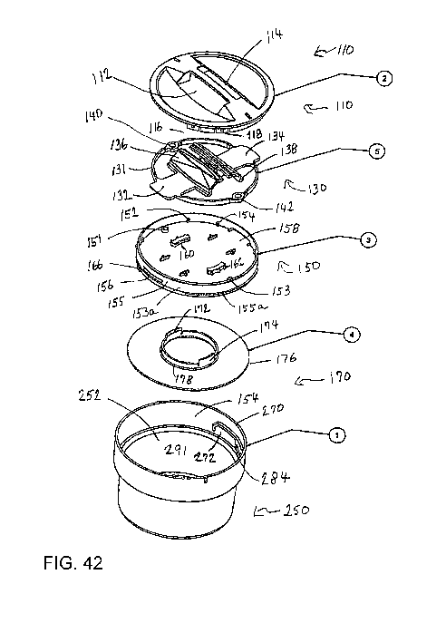
Figures 30 through 81 illustrate a preferred non-limiting embodiment for a
novel child
safety Cover in accordance with the present disclosure which can be used with
any of the
Containers shown in Figures 1 through 29, as well as other Containers. The
cover 100 can comprise
a top member 110, a locking member 130, a bottom member 150, a seal member 170
and a locking
base 190 formed at the opening of container 250. Container 250 will be
referenced to include all
types of Containers and not just the container shown in the drawing figures.
Top member 110 can be provided with a first aperture/opening 112 and a second
aperture/opening 114 on its top surface which be used for receipt of the tab
members 136 and 138
when cover 100 is assembled. The apertures 112 and 114 are large enough to
allow movement of
tab members 136 and 138 when the tab members are pinched inward by a user
during operation of
removing the cover 100 from its securement to container 250. One or more pairs
of assembly tab
116 and 118 having receiving apertures therein can be provided for connecting
to member 110 to
bottom member 150 during assembly of the cover 100. Male assembly protrusions
152 and 154
can be received within the apertures of each pair of assembly tabs 116 and 118
for securing bottom
member 150 to top member 110. As will be discussed below, prior to securing
bottom member
150 to top member 110, locking member 130 is disposed therebetween and
separately secured to
bottom member 150, such that tab member 136 and 138 are positioned within
apertures 112 and
114 of top member 110 and accessible to a user. Top member 110 can also be
provided with
markings or indicia on its upper surface which can be used for aligning top
member 110 (and cover
100) with marking or indicia at opening 252 of container 250 for certain steps
in releasing or
securing cover 100 at opening 252 of container 250.
Locking member 130 preferably includes a first male locking portion 132 having
an outer
end which preferably extends beyond the border/periphery 131 of locking member
130 (in an
extended orientation) and an opposite end secured to tab 136 and a second male
locking portion
134 having an outer end which also extends beyond border/periphery 131 (in an
extended
orientation) and an opposite end secured to tab 138. A first aperture 140 is
provided along
periphery 131 and a second aperture 142 is provided along periphery 131 which
mate with upward
extending protrusions or posts 151 and 153 of bottom member 150 for securing
locking member
130 to bottom member 150. Bottom member 150 also includes a sidewall 155
extending along its
CA 03043607 2019-05-10
WO 2018/093799 PCT/US2017/061644
13
outer periphery having a first slot or groove opening 156 and a second slot or
groove opening 158.
When locking member 130 is secured to bottom member 150, the outer end of
first male locking
portion 132 is inserted through opening 156 or 158 and the outer end of second
male locking
portion 134 is inserted through the other opening 158 or 156. Outer nubs on
the locking portions
can act as stop members when they come into contact with sidewall 155. By
squeezing or pinching
tabs 136 and 138 inward locking portions 132 and 134 are retracted and with
enough
squeezing/pinching force by the user, the locking portions can be retracted to
release their locking
configuration. The diameter of locking member 130 can be slightly less than
the diameter of
sidewall 155 to allow locking member 130 to be disposed within sidewall (with
the tabs 136 and
138 squeezed inward so as to retract the locking portions 132 and 134).
Preferably, by aligning
apertures 140 and 142 with post/protrusions 152 and 154, locking portions 132
and 134 will be
aligned with grooves 156 and 158. Bottom member 150 also includes a plurality
of cavities 160
and 162 that are preferably accessible (opened) from an undersurface of bottom
member 150.
Bottom member 150 also includes a static peg or protrusion member 166 which
comes into
play in connection with the second locking section for cover 100. Preferably,
bottom member 150
comprises at least two peg members 166 spaced apart from each other.
When securing seal member 170 to the bottom of bottom member 150 during
assembly,
similarly shaped protrusions 172 and 174 are received within cavities 160 and
162 of bottom
member 150. Seal member 170 is providing with an outer periphery edge 176. The
underneath
central area of bottom member 150 can also be provided with a circular groove
159, which can be
provided for receipt of the central upward circular flange 178. Seal member
170 preferably, though
not limiting, can have a central opening. Preferably, protrusions 172 and 174
extend upward from
circular flange 178 and cavities 160 and 162 extend from circular groove 159
in bottom member
150, such that protrusions 172 and 174 are received in cavities 160 and 162
and circular flange
178 is received within circular groove. Preferably, when seal member 170 is
properly secured to
bottom member 150 during assembly a space is provided between the upper
surface of seal
member 170 and the bottom edge of bottom member 150.
The internal wall 254 at opening 252 of container is provided with locking
sections 270
which mate or otherwise come into contact with locking portions 132 and 134 of
locking member
130 and peg members 166 of bottom member 150 when securing cover 100 to
container 250 at
opening 252. Though not considered limiting preferably two locking sections
270 are providing
CA 03043607 2019-05-10
WO 2018/093799 PCT/US2017/061644
14
on internal wall 254. Locking section 270 extends inward into opening 252 from
internal wall 254
to define stop/retaining sections for locking members 132 and 134 and peg
members 166 to safely
secure cover 100 to container 250. Locking section 270 is provided with a
first locking area 272
and a second locking area 284. First locking area 272 is provided with an
upper stop ledge 274 and
a lower receiving open end 276 and contains walls 278 and 280. Second locking
area 284 is
providing an upper stop ledge 286 and a lower receiving open end 288 and
contains walls 290 and
292.
When cover 100 is properly secured to container 250 at opening 252, the outer
end of
locking members 132 and 134 are positioned within first locking area 272 such
that any significant
side to side movement of cover 100 is prevented by locking members 132 and 134
coming into
contact with walls 278 and/or 280. Similarly, any significant upward movement
of cover 100 is
prevented by locking members 132 and 134 coming into contact with upper stop
ledge 274.
Additionally, while locking members 132 and 134 are positioned within locking
section 270,
locking peg members 166 are positioned within second locking area 284.
Similarly, any significant
side to side movement of cover 100 is prevented by peg members 166 coming into
contact with
walls 290 and/or 292 and any significant upward movement of cover 100 is
prevented by peg
members 166 coming into contact with upper stop ledge 286.
The multiple steps for releasing or removing cover 100 from securement to
container 250
at opening 252 is seen in Figures 39 and 40. Initially, the user squeezes tabs
136 and 138 inward
which causes locking members 132 and 134 to retract a sufficient amount of
distance that they are
no longer constrained by walls 278 and 280 and upper ledge 274 of locking
section 270. However,
at this point, cover 100 preferably is still secured to container 250 and
cannot be removed, as the
inward movement of tabs 136 and 138 does not affect the location of peg
members 166 within
second locking area 284. Thus, peg members 166 are still constrained by walls
290 and 292 and
upper edge 286 of locking section 270. Accordingly, the next step involves
moving peg member
166 from its position within second locking area 284.
Initially, the user preferably still squeezes tabs inward 136 and 138 inward
otherwise
locking members 132 and 134 would return to their original locking position.
As peg members
166 are static (i.e. secured in a fixed position to bottom member 150) and do
not move separately
like locking members 132 and 134, the entire cover 100 (since all components
of cover 100 are
secured to each other) must be moved in order to move peg members 166 out of
second receiving
CA 03043607 2019-05-10
WO 2018/093799 PCT/US2017/061644
area 284 of locking section 270. The diameter of cover 100 (with peg member
166 extending
outward from bottom member 150 is slightly less than opening 252, such that
cover 100 cannot be
moved sideways to position peg member 166 out of receiving area 284.
Furthermore, where two
peg members 166 and locking sections 270 are provided moving cover 100 to one
side to move
one peg member 166 out of its second locking area 284, would cause the other
peg member 166
to be positioned further within its corresponding second locking area 284,
such that cover 100
would still be partially secured to container 250. Thus, the release of peg
members 166 preferably
releases both (all) peg members 166 at the same time. To accomplish this, with
tab 136 and 138
still squeezed inward, the user pushes down on cover 100 which causes all peg
members 166 to
travel downward and out of their corresponding second locking areas through
lower open end 288.
At this point, cover 100 still cannot be removed from container 250, as
pulling up on cover
100 would causes peg members 166 to come into contact with locking section 270
and prevent
upward movement of cover 100. Accordingly, with tabs 136 and 138 still
squeezed inward the
final release step requires the user to twist cover 100 in either a clockwise
or counterclockwise
(depending on how the cover 100 is configured) direction until peg member 166
is no longer under
locking section 270 such that when the user pulls up on cover 100 there is no
protrusion within
opening 252 that comes into contact with peg members 166 allowing cover 100 to
be removed.
Outer wall 153a of bottom member 150 can also be provided positioning
protrusion(s) 155a.
Protrusions 155a preferably come into contact with one end of locking section
270 when cover
100 is twisted and upon contact can indicate to the user that cover 100 has
been twisted a sufficient
distance to ensure that peg members 166 will avoid locking sections 270 when
cover 100 is pulled
upwards by the user to open container 250. Preferably, cover 100 can only be
twisted in one
direction (either clockwise or counterclockwise, but preferably not both), as
if the user attempts to
twist cover 100 in the wrong direction peg member 166 will contact the portion
of locking section
270 that defines wall 280 and will not move any farther resulting in peg
member still be blocked
by locking section 270 if cover 100 is attempted to be pulled upward.
To secure cover 100 to an open container 250, preferably the indicia or
marking on top
section 110 can be aligned with marking/indicia provided on internal wall 254
of container 250
near or at the open end of opening 252. In one non-limiting embodiment, where
the
indicia/markings line up can also be the pint where positioning protrusions
155a come into contact
with one end of locking section 270. Tab 136 and 138 are squeezed inward and
cover 100 is pushed
CA 03043607 2019-05-10
WO 2018/093799 PCT/US2017/061644
16
downward in opening 252 until seal 170 or bottom member 150 (if no seal is
provided) comes into
contact with an inner ledge 291 contained within opening 252. At this point of
contact, peg member
166 is positioned low enough with respect to locking section 270 such that
when the user twists
cover 100 counterclockwise (i.e. the direction opposite to the direction
twisted or turned to open
or remove cover 100) peg member 166 will be positioned underneath section
locking area 284
preferably in conjunction with protrusion 155a coming into contact with an end
of locking section
270. At this point, the user releases the pinch or squeeze on tabs 136 and 138
and cover 100 is
safely secured to container 250.
Seal 170 can be a semi pliable layer and not a rigid of a material as the
other components
of cover 100. The pliable layer can be preferably compressed to release a
locking mechanism. A
gasket member can also be added to cover 100 and positioned within one of the
components of
cover 100 or at a point along opening 252, such as, though not limiting,
underneath locking section
270. Furthermore, the orientation of the components and sections can be
configured to allow for
either right-handed operation or left-handed operation.
The materials used for making the various describe components and Containers
are not
considered limited to any particular material(s). In one non-limiting
embodiment, plastic material
can be used. In another non-limiting embodiment some or all of the components
of cover 100 can
be constructed from metal. Additionally, the Containers can be clear, opaque,
transparent, etc. and
can also come in a variety of colors. The Containers are also not considered
limited to any
particular color.
All shapes, materials, uses, sizes or dimensions shown in the drawings and/or
described
herein are by way of non-limiting examples and are not considered limited and
the various
Containers, Covers, etc. can be provided in other shapes, materials, uses,
sizes and dimensions
which are also considered to be within the scope of the disclosure.
With the use of cover 100, the Container that cover 100 is secured to becomes
reusable
while maintaining its child safety or child proof characteristics it had prior
to being initially
opened.
All components and containers can be made from several different
construction/manufacturing methods, such as, but not limited to, molds,
injection molding, blow
molding, 3D printers, etc
CA 03043607 2019-05-10
WO 2018/093799 PCT/US2017/061644
17
Additionally, cover 100 and the concepts of a child safety device can be used
with other
non-container uses and products and such uses are also considered within the
scope of the
disclosure.
Accordingly, the disclosed novel cover 100 provides for a child safety cover
to help prevent
accidental openings of container 250 and avoiding exposing the content of the
container to a child,
which could be lead to a dangerous situation to the child's safety.
All locations, sizes, shapes, measurements, amounts, angles, component or part
locations,
configurations, temperatures, weights, locking mechanisms, dimensions, values,
percentages,
materials, orientations, etc. discussed above or shown in the drawings are
merely by way of
example and are not considered limiting and other locations, sizes, shapes,
measurements,
amounts, angles, component or part locations, configurations, temperatures,
weights, locking
mechanisms, dimensions, values, percentages, materials, orientations etc. can
be chosen and used
and all are considered within the scope of the disclosure.
Dimensions of certain parts as shown in the drawings may have been modified
and/or
exaggerated for the purpose of clarity of illustration and are not considered
limiting.
Unless feature(s), part(s), component(s), characteristic(s) or function(s)
described in the
specification or shown in the drawings for a claim element, claim step or
claim term specifically
appear in the claim with the claim element, claim step or claim term, then the
inventor does not
consider such feature(s), part(s), component(s), characteristic(s) or
function(s) to be included for
the claim element, claim step or claim term in the claim when and if the claim
element, claim step
or claim term is interpreted or construed, whether during prosecution of this
application or in
litigation or similar proceeding. Similarly, with respect to any "means for"
elements in the claims,
the inventor considers such language to require only the minimal amount of
features, components,
steps, or parts from the specification to achieve the function of the "means
for" language and not
all of the features, components, steps or parts describe in the specification
that are related or could
be attributed to the function of the "means for" language.
While the above novel Containers and Cover disclosure have been described in
certain
terms and disclosed certain embodiments or modifications, persons skilled in
the art who have
acquainted themselves with the disclosure will appreciate that it is not
necessarily limited by such
terms, nor to the specific embodiments and modification disclosed herein.
Thus, a wide variety of
CA 03043607 2019-05-10
WO 2018/093799 PCT/US2017/061644
18
alternatives, suggested by the teachings herein, can be practiced without
departing from the spirit
of the disclosed Containers and Covers, and rights to such alternatives are
particularly reserved
and considered within the scope of the disclosure.