Note: Descriptions are shown in the official language in which they were submitted.
Monitoring of Physical Training Events
TECHNICAL FIELD
[0002] This document relates to systems and techniques for automatically
identifying characteristics of movement of a sports ball during athletic
training drills,
and of using such monitored motion to make determinations about physical
ability
of a test subject.
BACKGROUND
[0003] Athletics has become an integral part of society, with multiple
television
channels dedicated to sporting events, with professional athletes promoting
all sorts
of products, and with the public holding star athletes¨both amateur and
professional¨in high regard, so as to support financial rewards such as
college
scholarships, sponsorship opportunities, and other revenue-generating careers.
With greater general attention on athletics comes greater attention on
improving
athletic performance. Today's athletes, beginning as early as the elementary
school level, specialize in particular areas and train year-round to improve
their
1
CA 3043730 2019-05-17
skills and their conditioning. With athletics leading to a possibly lucrative
career for
some, and to academic assistance in the form of scholarships to others, more
and
more athletes have looked to improve their performance in various manners.
[0004] Good coaching and personal dedication are some of the best known
ways to improve an athlete's performance. A talented coach can often observe
subtle problems in an athlete's style of play, and can direct the player to
correct
those problems. Likewise, a talented trainer can direct an athlete to follow
certain
regimens to improve physiological weaknesses.
[0005] Despite the talent and experience obtained by many top coaches or
athletic experts, human perception can capture and fully appreciate only a
small
subset of the factors that affect an athlete's performance. Thus, despite
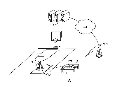
years of
observing how different athletes compete in a given sport or having competed
for
many years themselves, the most highly skilled trainers and coaches still do
not
have the ability to quantify very small differences in motion of what they
see. These
differences in motion can be the most important elements in comparing and
diagnosing a player's skill. Also, techniques that rely on human observation
and
judgment are prone to a high degree of opinion or bias based on the
perceptions of
any single observer. This bias, and the wide variability of what any given
observer
believes they are seeing, negatively affects the advice that coaches and
trainers
can provide to athletes, and also negatively affects the athletes' perception
of the
advice they are being given (i.e., an athlete may ignore good advice if they
think
that the provider of the advice does not appreciate their abilities).
2
CA 3043730 2019-05-17
[0006] In some sports that require a combination of physical athletic
skill, muscle
memory, and hand-eye coordination skills to be used while simultaneously
moving
an athletic object, such as a ball, while under pressure situations, the
ability to
objectively quantify and compare discrete skill differences between players is
almost impossible using human perception. The net effect of the inability to
standardize the unseen elements of skill has been an over-reliance on only the
measurable physical aspects of certain sports, such as athletic speed,
strength, and
jumping, which causes many highly skilled athletes to be overlooked.
SUMMARY
[0007] This document describes systems and techniques that may be used to
quantify and benchmark an athlete's current skill proficiency using sensors
that
capture discrete movements of an athletic device, such as a basketball or
soccer
ball, while it is in motion so as to link athletic proficiency of the athlete
to their ability
to control the athletic device, compare the related performance of the athlete
controlling the movement of the athletic device to the performance of other
athletes
that has been aggregated to provide base performance indicators, and to
provide
feedback for an athlete so that they can improve their performance.
[0008] To measure the proficiency of athletic skills, motion sensor
devices may
be used to monitor the movement of a sports ball to assess various forces that
an
athlete applies to the ball, such as forces that create acceleration and spin
on the
ball. Computer systems can measure these forces to recognize patterns of the
forces that reflect a degree to which the athlete has trained his or her
muscles and
hand-eye coordination to apply those forces consistently. Computer-implemented
3
CA 3043730 2019-05-17
systems can perform a quick and consistent analysis of the sensor measurements
so as to create a summary of quantified results for comparative purposes. With
algorithms that can analyze the data in a consistent and fast manner, the
related
output of the devices can be reliably delivered to athletes in a time
efficient manner
so as to provide immediate and meaningful improvement feedback.
[0009] Motion-related data from the athletic device, such as acceleration
and
rotation data, can be identified and compiled into meaningful samples, and the
samples can be compared to a large number of other samples collected in a
similar
fashion from athletes having known skill levels. For example, the
characteristics of
athletic performance for a certain action or athletic drill performed while
using an
athletic device can be determined for each level of play, e.g., grade school,
high
school, lower level college (e.g., division II or junior college), higher
level college,
professional, and elite or all star. Sampled data for a particular athlete can
then be
compared to aggregated data, collected using the same motion sensing
technologies and while performing the same drills in the same fashion, from
other
athletes that were known to be performing at each of these levels, and a level
of
performance for the particular athlete may thus be determined.
[0010] The drills can be predetermined and matched between and among test
subjects so that the resulting data can be matched and compared as between
individuals in a statistically significant manner. Drills are defined multi-
step physical
processes that an athlete performs, such as dribbling in a particular pattern,
shooting a certain number of shots from a defined point on a court, and
running
through a pattern, such as through cones or on a line that can be applied to a
floor.
4
CA 3043730 2019-05-17
[0011] As a result, such techniques can provide an indication to an athlete
or to
recruiting personnel regarding the objective skill level at which the athlete
is
performing, either for a particular skill set, or overall for an entire sport.
In addition,
the results may provide constructive feedback by suggesting exercises that the
athlete can undertake to improve any deficiencies that the system recognized
when
comparing the athlete's data to that of other athletes.
[0012] While some exercises may simulate actual game-type athletic
actions,
such as shooting a ball or puck, other exercises may test more general
athletic
abilities, such as strength, stamina, and quickness. For example, in one test,
an
athlete may be asked to lay on his or her back and throw a weighted bal
repeatedly
into the air. The explosiveness of the throw can indicate strength that is
relevant,
for example, for two-handed basketball passes or blocking by an offensive
lineman.
The level at which he athlete maintains that level of explosiveness (e.g., as
measure by motions sensors such as accelerometers in the ball) may provide an
indication of the athlete's stamina for such activity. In another exercise, an
athlete
may be asked to jump vertically a number of times. Again, a motion sensor may
be
embedded in a ball and the athlete may hold the ball as he or she jumps so
that the
explosiveness and stamina of the athlete may be measures. Alternatively, or in
addition, sensors may be attached to the athlete, such as in a vest that the
athlete
wears during an exercise. In a third exercise, an athlete may be asked to
perform
sit-ups with side twists, and motion sensors in a ball held by the athlete, on
the
athlete's upper body, and/or pressure sensors on the floor below the athlete
may be
used to measured the athlete's core strength. Finally, an athlete may be
CA 3043730 2019-05-17
challenged to chest pass a heavy ball from one pylon to another while chasing
after the ball. Helpers may place the ball on the next pylon in front of the
athlete.
Again, the ball may include motion sensors. Such a test may help identify
passing strength and running quickness for an athlete.
[0013] In
certain implementations, such systems and techniques may provide
one or more advantages. For example, athletes can be analyzed quickly by
completing a number of drills through which the movement of the ball or balls
are
instantly recorded and easily transferred to a computing system. Also, the
systems can record facets of an athlete's performance that would not be
observable by a coach watching the athlete, particularly for fast-moving
sports
that require a combination of athleticism, muscle memory, vision, and the like
to
succeed. In addition, the analysis provided by the techniques provided herein
can be consistent and unbiased so as to provide high quality, objective
analysis
in a highly scalable system without the need for personal training for
numerous
observers. For example, motion sensing testing systems can be deployed
nationally for operation by technicians who have only limited amounts of
training.
The analysis, like the data collection, can be unbiased and scalable, so that
it
can give an athlete a fair evaluation without concern that assertions of
favoritism
will be made, and can be completed without needing to train numerous analysts
as a system grows.
[0014] In accordance with an aspect of the present invention, there is
provided
a computer-implemented athletic performance analysis method, comprising:
obtaining, at a computer system, first motion data generated by a test subject
moving a test ball containing motion sensors through a predetermined exercise;
6
CA 3043730 2019-05-17
analyzing in the first motion data, with the computer system, the data from
the
inertial sensors; and providing to a remote computer at a location of the
subject
a report regarding the first motion data, the report reflecting a comparison
of the
first motion data with corresponding motion data of other users who have
performed the predetermined exercise; wherein the predetermined exercise
comprises repeatedly performing a common motion, and the report reflects the
subject's stamina during repeated performance of the common motion as
compared to other test subjects..
[0014a] In accordance with a further aspect of the present invention, there is
provided An article comprising one or more tangible computer-readable data
storage media containing program code operable to cause one or more
machines to perform operations, the operations comprising: obtaining, at a
computer system, first motion data generated by a test subject moving a test
ball
containing motion sensors through a predetermined exercise; analyzing in the
first motion data, with the computer system, the data from the inertial
sensors;
and providing to a remote computer at a location of the subject a report
regarding the first motion data, the report reflecting a comparison of the
first
motion data with corresponding motion data of other users who have performed
the predetermined exercise; wherein the predetermined exercise comprises
repeatedly performing a common motion, and the report reflects the subject's
stamina during repeated performance of the common motion as compare to
other test subjects.
6a
CA 3043730 2019-05-17
[0015] The details of one or more embodiments are set forth in the accompa-
nying drawings and the description below. Other features and advantages will
be
apparent from the description and drawings, and from the claims.
DESCRIPTION OF DRAWINGS
[0016] FIG. 1A is a conceptual diagram of a system for electronically
measuring
athletic performance and providing feedback on the performance.
[0017] FIG. 1B shows a system for interfacing sensored sports balls to a
home
consumer electronics system.
[0018] FIG. 2A is a block diagram of an illustrative computer system for
comparing performance indicators for an athlete to aggregated performance
indicators for a plurality of other athletes.
[0019] FIG. 2B is a block diagram of a computer-based system for evaluating
athletic performance.
[0020] FIGs. 3A and 3B are flow charts of example processes for obtaining
motion data relating to an athlete's performance.
[0021] FIG. 3C is a flow chart for identifying particular events during a
drill that
involves bouncing a ball.
[0022] FIGs. 4A-4B show sample motion data from basketball shots taken
after
a pass.
[0023] FIGs. 5A and 56 show parameters that can define a basketball shot.
[0024] FIG. 6 shows example gyro and accelerometer data for a basketball
shot.
[0025] FIG. 7 shows example data from a ball being tossed upward from the
chest of a lying subject.
7
CA 3043730 2019-05-17
[0026] FIG. 8 shows example motion data from a jumping subject.
[0027] FIG. 9 shows example motion data from a subject performing sit ups
with
side taps.
[0028] FIG. 10 shows schematically a set up for a throwing and running
drill.
[0029] FIG. 11 shows motion data for a repetitive throwing and running
drill.
[0030] FIG. 12 shows a comparison between a process for making an non-
instrumented basketball (or similar type of sporting ball) and an instrumented
basketball.
[0031] 13A-13K are graphs that show how raw motion data may be reduced and
filtered into a form suitable for analysis of particular basketball motion,
such as
dribbling.
[0032] FIG. 14 shows an example of a computer device and a mobile computer
device that can be used to implement the techniques described here.
[0033] Like reference symbols in the various drawings indicate like
elements.
DETAILED DESCRIPTION
[0034] This document describes systems and techniques for capturing and
evaluating athletic performance in a repeatable and objective manner by
measuring
athletes who have been instructed to perform certain drills that match drills
that
other athletes have also performed. In general, a sporting device such as a
basketball or other ball can be provided with, or be observed by, motion
sensors,
such as accelerometers and angular rate gyros, to record data about the manner
in
which an athlete manipulates the sporting device. Additional data may be
captured
from the athlete, such as via laser-based motion recorders, pressure sensitive
pads,
8
CA 3043730 2019-05-17
and shoe-based sensors. The athlete may be directed through one or more
drills,
such as a dribbling or shooting drill, and his or her actions may be recorded
through
the various sensors as they complete the drill. The drill may be well defined
so that
the data that is captured may be compared to other instances of the drill,
including
instances in which the same athlete performed the drill at different periods
of time,
and instances in which other athletes performed the drill.
[0035] The motion data may be captured on a computer system in proximity to
the location where the athlete performed the drill. The capturing of the data
may
occur, for example, via wireless communication between a sensor assembly
inside
the sporting device and a wireless transceiver attached to a computer, such as
via a
USB port or similar interface. The motion data may then be transformed,
sampled,
and converted in various manners and may be compared to data from other
athletes that has been aggregated for later statistical or similar analysis.
The other
athletes may have provided indications about their level of athletic
performance,
such as whether they are varsity high school players, junior college players,
division
I players, professional players, or other levels of player. If those other
athletes
performed the same or similar drills under controlled conditions (by being
instructed
by, and observed by, a technician to ensure that they follow the appropriate
steps of
a drill), their aggregated data can be compared to the data for the first
athlete to
determine where, on a continuum of skill levels like that just described, the
athlete
falls.
[0036]
Such an analysis may be simple, such as by being based on a single drill,
or it may be complex and involve a large number of drills that test a variety
of skill
9
CA 3043730 2019-05-17
sets for an athlete. The simple testing may be conducted as an initial test to
see if
an athlete is interested in further testing. For example, testing may be
provided at a
public event like an AAU tournament or a 3-on-3 basketball tournament. More
complex testing may also, or alternatively, be conducted. For example,
athletes
may attend more extensive testing at fixed athletic facilities, such as
facilities that
are relatively common in major metro areas. The additional testing may test a
variety of drills that include tests for ball handling, jumping, shooting, and
other
similar skills.
[0037] The analysis may involve identifying individual sub-events within a
drill,
such as individual instances of a basketball bouncing off the floor and
entering/exiting an athlete's hand. Such sub-event may be identified by
running a
time-wise window across the motion data recovered from a drill, and looking
for
sudden accelerations or other changes that may represent palming or bouncing.
The analysis may also involve isolating instances in which the athlete has
lost
control of the ball, such as by identifying the absence of an adequate
acceleration
in a particular time window (thus indicating that the athlete let the ball
bounce
multiple times without dribbling it and/or was required to dribble the ball at
a low
height and high frequency to regain control over it).
[0038] The test results may be generated at a central facility that is
remote from
the various test centers. Such an arrangement may permit easy deployment of
the
system, with sensor-fitted balls and wireless transceivers being the only
hardware
that needs to be sent to remote sites in many implementations. Client
computers
such as laptop computers may be provided by a technician, and may communicate
CA 3043730 2019-05-17
with a remote server over the internet, including through a web browser that
can
have a downloaded plug-in for controlling communication with the sporting
device
and for uploading the gathered information to the server.
[0039] The server may in turn include a web server, and the client
computer may
receive information back from the server in the form of an XML and/or HTML
document that can be shown or otherwise provided to the athlete, with a
summary
of the data that was reviewed for the athlete, and a list of instructions and
exercises
for the athlete in order for the athlete to address any weaknesses that were
indicated by the testing.
[0040] Athletes may also be encouraged to conduct testing at multiple
different
time periods. Such testing may measure the relative progress that the athlete
has
made. Such relative progress may also be compared to aggregated data on the
progress of other athletes. The evidence of progress for the particular
athlete may
be fit in a number of known mathematical and statistical manners so as to
produce
a prediction of the athlete's near term and longer term expected progress if
the
athlete continues at a pace of development that matches the development
measure
for other athletes of similar progression.
[0041] Referring now more particularly to the figures, FIG. 1 is a
conceptual
diagram of a system 100 for electronically measuring athletic performance and
providing feedback on the performance. The system 100 generally includes a sub-
system that is local to one or more athletes who are being tested, and a sub-
system
that is remote from the athletes and includes one or more servers. Although a
11
CA 3043730 2019-05-17
separated system is shown here, all of the processing for the system may also
be
localized at a single location.
[0042] A separated system may provide a number of advantages, however. For
example, it may eliminate the need to deploy and maintain computers and
software
in the field. Rather, only limited technology, such as one or more sporting
devices
(e.g., balls, shoes, clubs, etc.) need be sent out, and software may be
downloaded
to computers (such as laptop computers) that are already in the field, such as
via a
web browser plug-in that manages communications with the sporting device and
uploads device data. As a result, a company operating the system may reduce
its
capital costs significantly by using computers that are already owned by field
personnel and are being used for other purposes. In addition, the company can
better control who is using its technology, by maintaining ownership, for
example, of
the sporting devices, so that a field representative must return the device
when their
term of representation is over. Also, when field deployment of software occurs
via
download over the internet, a company can push out the programs more easily,
and
may also keep them updated regularly with little effort. Moreover, such a
separated
system permits the company to maintain better control over its analysis code
so that
the code is not easily taken and provided to a competitor, and so that it can
be
updated and kept fresh in a very controllable manner.
[0043] A hybrid approach to splitting the duties of the in-field sub-system
and a
central sub-system can also be pursued. For example, a client device such as a
laptop computer may be provided with code and data that is sufficient to test
an
athlete in one entry-level drill, such as dribbling a figure eight. Such
distribution of
12
CA 3043730 2019-05-17
_
basic testing code may permit the testing to occur more quickly and reliably
than if a
round-trip to a central server were required. Such reliability can be
important for
entry-level testing also, because frequently such testing would occur at
various
festivals and tournaments that are far from dedicated IT equipment.
[0044] In the hybrid system, the server system could be used for
subsequent
and more extensive testing, after athletes have been introduced to the system
and
have decided they would like to receive additional testing and guidance. In
this
manner, the system 100 can be introduced conveniently to athletes and they can
be
given an inexpensive trial of the system's capabilities with the entry-level
drill.
Although security may be compromised for testing of the one drill (because the
analysis code will have been sent to remote client devices), a competitor
could not
make much from the one drill in any event, so the risk to security is
minimized.
[0045] In FIG. 1, the local computer sub-system is made up of a
laptop computer
108, a wireless transceiver 110, and a printer 112. The computer 108 may take
other forms and may be loaded with software to cause an athlete's data (from
the
measured motion of a sporting device that the athlete manipulated and/otr
other
sources) to be analyzed, and may cause reports to be provided to the athlete.
The
computer 108 may be loaded with native applications to receive such input and
produce such reports, and to also analyze the input data with respect to
similar data
from other athletes. Alternatively, the computer 108 may be loaded with basic
workplace applications, such as a web browser, and the system 100 may provide
a
downloadable plug-in for the browser that will control communications with the
transceiver 110 and with a server.
13
CA 3043730 2019-05-17
[0046] The transceiver 110 may take a variety of forms, and may be directed
to
capturing motion data from a sporting device in the form of a basketball 104
in this
example. The basketball 104 may be of a common size and shape, and may
contain a sensor assembly that includes accelerometers and angular rate gyros
mounted inside it, in a way that does not interfere substantially with the
handling of
the ball, to capture motion of the ball 104 in a manner that is usable to the
system
100. The transceiver 110 may in turn communicate with the computer 108 in a
familiar manner, such as through a USB port or the like, so as to make
relatively
simple the use of the computer 108 with the system 100 to capture motion data.
[0047] The printer 112 is shown as an example of one way in which a report
on
an athlete's performance can be presented to the athlete. For example, certain
numerical figures or graphs may be generated to visually show where the
athlete
scores on a continuum of skill levels. In addition, recommendations may be
generated in a textual format to be given to the athlete, with particular
instructions
on how the athlete can improve their performance, including suggested
exercises or
drills to perform in order to improve the athlete's muscle memory for a
particular
task. For example, if the testing of an athlete indicates that the athlete
does not
release the ball during a dribble with adequate velocity, the system 100 can
recommend drills and conditioning routines to address such a situation.
[0048] In addition to being provided on paper from printer 112, information
may
be provided to an athlete regarding his or her performance via other
mechanisms.
For example, data for an athlete may be copied to a thumb flash drive or other
similar mechanism. The athlete may then return to a next testing session and
14
CA 3043730 2019-05-17
provide the memory mechanism for use in comparing the athlete's skills at an
earlier time to their current skills, and extending out any recognized trends
to give
the athlete or someone reviewing the athlete an opportunity to see if the
athlete is
similar in skills to other athletes who have excelled over time, or have
stalled and
fallen behind comparable athletes.
[0049] The data for an athlete may also be stored in the system 100, and
the
athlete may provide identification information in subsequent visits so that
prior test
data for the athlete is joined with subsequent test data. Access to data may
be
provided to the athlete via a message sent to the athlete (e.g., via text
message or
e-mail) or by providing the athlete with log in credentials to a central site.
A
combination of such methods for provided the athlete with access to the data
may
also be employed. In addition, reporting tools may be provided under any of
the
examples above, so that the athlete may return home and produce custom reports
and otherwise manipulate the data on their performance.
[0050] An athlete 102 is shown in FIG. 1 dribbling the basketball 104. For
example, the athlete may be instructed to dribble the ball in a figure-eight
pattern
several times, or for a fixed number of times so as to record a statistically
relevant
sample of items to record and analyze, while motion data is being captured by
sensors in the basketball 104 and perhaps via other sensors. The athlete is
also
shown as performing on a pad 106. The pad 106 may be pressure sensitive and
may provide additional data that may be coordinated with the motion data from
the
sporting device 104. For example, the relative timing between up and down
motion
CA 3043730 2019-05-17
of a ball and contact timing of a basketball player's feet may indicate
certain room
for improvement in the athlete's skill set.
[0051] In addition, other sensors may be employed along with the sensors
in the
sporting device, such as laser location finders that may indicate the relative
positions of points on the athlete's 102 body, or motion data of the
basketball 104
that cannot be fully captured by sensors inside the ball. Certain sensors may
also
identify information relating to the actual time that a drill starts and
stops, or how
quickly an athlete moved from point A to point B while simultaneously
controlling
the athletic device, how consistently the athlete handles the ball, the
variability
between dribbles, etc. Also, sensors may be used to determine athleticism,
such
as in vertical jump tests, both to measure the height of the athlete off the
ground
and to measure the acceleration of the athlete off the floor.
[0052] The sensors may generate a variety of data types. The sensors can
measure athletic stride, number of impacts, change of direction, etc, while
sensors
in a ball would capture the muscle memory skills associated with handling the
ball
while moving in very quick and short bursts. Also, the timing of data for
various
sensors may be aligned and synchronized so as to delver more information on
the
athlete's performance. For example, laser-based sensors, when combined with in-
ball sensors, may provide an indication when a player loses a dribble during a
drill,
even in situations where either sensor group alone would not make the same
determination.
[0053] Sensor-equipped specialized athletic devices that differ from the
corresponding devices that are used in competition may also be used for
testing
16
CA 3043730 2019-05-17
_
athletes. For example, sensors may be provided in a weighted ball, and an
athlete
may be directed to execute drills that can deliver predictive or diagnostic
data on a
player's core strength. For example, the heavy ball can be thrown, and the
sensors can capture acceleration, distance, and speed. As another example, an
athlete can perform a series of repetitive drills with the torso, such as
situps. The
sensors can measure force, acceleration or other movements, the average and
median of these measurements, and any degradation of these elements over the
course of the entire drill. These measurements can be used to benchmark,
compare, and predict core athletic strength that is critical in many sports.
[0054] Certain of the information may be compared to aggregated
data for other
athletes, while certain data may be provided in a form that does not involve
such
comparison. For example, drill data for particular skills may be compared to
drill
data for other athletes, while core strength measurements may simply be
provided
in raw form or in some revised form (e.g., on a scale of 1 to 10) but without
the
need to place such numbers into some preexisting skill level relative to other
athletes. In this manner, various sorts of data may be made available for
review by
an athlete or by others from a single location ¨ whether the particular data
is best
presented in comparison or as an absolute.
[0055] The local client sub-system may be connected to the
server sub-system
through a wireless connection, such as an aircard or similar structure or a
WiFi card
and WiFi hot spot. A network 114, such as a cellular data carrier network 114
may
transfer the data and communicate through a network 116 such as the internet,
to
the server sub-system shown here as a single server 118, but which could
include a
17
CA 3043730 2019-05-17
large number of servers to receive various types of requests. The server 118,
as
described in more detail below, will have previously been provided with data
reflecting skills for a number of other athletes who already ran the relevant
drill or
drills. The previously processed data will also indicate the skill level of
several of
the athletes.
[0056] The
server 118 can thus compare the data representing the performance
of one athlete acquired by the client sub-system, to the information that is
aggregated for performances of a group of other athletes whose relative levels
of
development are generally known. The server may then return to the computer
108, through the networks 114 and 116, information that can reflect such a
determination and provide additional helpful data and advice to the athlete.
For
example, the computer 108 may be used to print out a number of pages of mark-
up
language material (e.g., HTML) that include data and graphs to show the
athlete
what was measured from them, and what comparable values have been observed
for players from various levels of a sport. In addition, various instructions
can be
provided in a similar manner, which the athlete can take home with them and
read
to improve a particular skill set or drill. Such data and reports may be
provided via
printer 112, or via an electronic file such as an HTML or PDF file stored to
removable portable media that is given to or provided by the athlete. For
example,
a sponsor at an athletic event may supply free flash memory containing the
sponsor's name, and the data for an athlete may be stored onto the flash
memory
by attaching the flash memory in a well-known manner (e.g., through a USB
port).
18
CA 3043730 2019-05-17
[0057] An athlete can also capture data to be used in customizing a
videogame
experience. The athlete can first perform a variety of drills to obtain
statistics
indicative of their overall current skill levels in a sport. They may then
have the
figures loaded to portable memory devices that can be used with videogame
systems, whether console or PC. Such athletes may then load the data to a game
that involves athletic performance that uses the skills tested by the athlete,
and their
character or avatar in the game may perform according to their actual real-
world
skill level, with multiple different variables being identified to define the
full
performance palette for the athlete. In this manner, friends may set up head-
to-
head battles in sporting games, where their own personal skill levels affect
how the
simulated videogame contest will turn out. The athletes may also thus be
motivated
to return for additional testing after they have practiced so that they can
have better
baseline skill numbers that will improve their performance vis-a-vis other
players in
the game.
[0058] FIG. 1B shows a system 120 for interfacing sensored sports balls 124
to
a home consumer electronics system 122. In general, the system 120 may be used
to permit a consumer to practice with the sports ball, such as in their
driveway, and
then immediately enter their home and have data regarding their skills
uploaded to
their personal computer, console gaming system, or mobile computing device
(e.g.,
smart phone or app phone).
[0059] In the figure, two athletes each hold one of the balls 124, which in
this
example are basketballs. Each of the athletes may have just finished
completing a
series of drills, such as performing dribbles in a figure 8 through the legs,
19
CA 3043730 2019-05-17
performing dribbles around the body in a circle, dribble while running through
certain forms, and the like. Each athlete may perform one drill at a time, or
may
use materials such as a guidebook to perform drills or exercises in order, and
the
balls 124 may store motion data, such as in the manners discussed above and
below, for each such drill. Separators may be provided between sets of data
for
each drill so that distinctions between each drill may be determined during
later
data analysis.
[0060] As
shown in the figure, electronic assemblies inside each of the balls are
communicating data wirelessly either with a smartphone 134 or a wireless
router or
switch 132. Such communication may occur in familiar manners, such as by using
standard BLUETOOTH or WiFi protocols and mechanisms at each of the devices.
The balls can announce themselves after a set period of inactivity has expired
after
drills have been performed, may perform a handshaking process, and may begin
uploading whatever information they have obtained from the motion of the balls
124
during the drills. The smartphone 134, a personal computer 126 (e.g., a
laptop,
netbook, or desktop computer), or a videogame console 128 (e.g., a MICROSOFT
XBOX, NINTENDO WII, or SONY PS/3) connecte to a video display 130 (e.g., a
high definition television) may be the destination of the data and may include
software for storing the information about the motion of the balls 124 and
further
transmitting such information (perhaps after some level of reformatting) or
analyzing
the information.
[0061] The consumer electronics system 122 may include each of the consumer
electronics devices discussed here (e.g., console gaming system 128,
smartphone
CA 3043730 2019-05-17
134, or personal computer 126), which may in turn communicate over a local
area
network 138, which may be partly wired (e.g., IEEE 802.3x) and partly wireless
(e.g., IEEE 802.11x).
[0062] One or more of the devices may also communicate through a larger
network, including the internet 130 with a server system 132. Such a server
system
132 may provide functionality like that discussed above and below for
analyzing an
athlete's performance data, including by comparing it to performance data for
other
athletes. Such information may be processed, and the results may be downloaded
back to one of the consumer electronics devices, including through wireless
network 136.
[0063] In operation of the system 120, the two athletes may each have a
ball
124 or may take turns with a ball, and may, for example, go outside in a
driveway
while performing a number of drills that may be outlined on a paper card one
of
them received with a videogame (where the instrumented, or sensored, ball may
have been integrally packaged with the game disk, cartridge, or download
code).
They may each perform the requisite drills with the ball or balls 124, and
then
upload data that represents motion data for their drills to one of the
consumer
electronics devices 126, 128, 134.
[0064] In one example, such data may be further uploaded to the server
system
132, which may analyze the data and provide information to each of the
athletes
that explains to them, such as graphically or in tabular form, how they
compare to
each other and to other athletes in terms of basketball skills that are
reflected by the
21
CA 3043730 2019-05-17
drills they performed. Other uses of the information may also be made, such as
described above and below.
[0065]
Alternatively, or in addition, the data from the balls 124 or data produced
from such ball data and that reflects information about the athletes'
performance in
the drills, may be provided to one or more of the consumer devices 126, 128,
134.
Such devices may be loaded with a sports videogame that permits competition
against a computerized opponent by an avatar controlled by the player, or head-
to-
head competition between two players. The data may thus be used to affect the
athletic performance of each players/athlete's avatar. For example, if the
data from
the drills indicates that the first athlete dribbles strong with the right
hand, the
athlete's avatar in the video game will tend to go stronger to the right. Such
provision of the athlete's ability to the avatar may be absolute or relative,
or a mix of
the two. For example, if the test data shows that the athlete's skills are
horrible,
their avatar may also be horrible in a videogame. Alternatively, the general
skill
level of the athlete may be raised to some even norm with that of the other
players,
and the relative strengths of the player may be emphasized. For example,
perhaps
the athlete was horrible going right and even worse going left. In such a
situation,
their avatar might play as going strong to the right and normal to the left,
with an
average ability that matches that of the second athlete so that the videogame
is
evenly matched. Nonetheless, absolute skill levels have benefits in that they
encourage athletes to improve their overall skill level and to get better at
playing the
game in real life, in the process.
22
CA 3043730 2019-05-17
[0066] FIG. 2A is a block diagram of an illustrative computer system 200
for
comparing performance indicators for an athlete to aggregated performance
indicators for a plurality of other athletes. In general, the system 200 is
similar in
arrangement to system 100 in FIG. 1, but more detail is shown here about a
server
system 202 that may be used to provide evaluation data for athletic
performance.
[0067] Starting at the client side and then moving to the server system
202, there
is shown a sporting device in the form of a basketball 228, which may
communicate
motion data that is measured by sensors inside the basketball 228 with a
wireless
transceiver 226. The wireless transceiver 226 may in turn provide the motion
data
to a computer 222 that may pass the information to a network 220 such as the
internet and/or a wireless network like a WiFi network or cellular data
network, and
on to the server system 202. The computer 222 is also provided with one or
more
output devices in the form of a printer 224 and computer monitor, and may also
have ports for writing to portable memory devices carried by athletes who are
tested
by the system 200. The client-side system in this example can be operated in a
manner similar to the system 100 described in FIG. 1.
[0068] On the server side (which again, may include one or a number of
server
computers, including web servers, database servers, and other computers), the
server system 202 includes a number of components to assist in processing data
regarding athletes' performance in a number of drills. (which may be among a
number of additional components that are omitted here for clarity)
[0069] First, a number of data stores 212-218 hold data that is relevant
to the
athletic evaluation functions. For example, a classified data store 212
includes
23
CA 3043730 2019-05-17
information from past athletes whose performance data has been generated and
who are classified into certain skill levels. The data may be aggregated from
across
a large number of athletes so as to make the data meaningful. Also, each set
of
data may be correlated to a particular drill or exercise performed by the
athlete, so
that the data can be properly compared to data for other athletes that
performed a
matching drill or exercise. (A matching drill is a drill that is the same as a
first drill or
that includes some substantial superset or subset of the first drill.)
[0070] Classification rules dataset 214 may store data representing rules
that
are derived from analyzing the classified data, and may include heuristic
rules or
other rules to apply to incoming data to determine an appropriate skill level
of an
athlete who generated the data. For example, a set of rules may be combined to
determine a skill level of a free throw shooter, such as the number of times a
free
throw rotates and the hang time and entry angle of a free throw.
[0071] Client data store 216 may store two or more types of data. For
example,
it may store information about the particular client computer 222 that is
sending
testing data to the server system 202, such that an account associated with
the
computer 222 or with a login made through the computer 222 can be debited.
Such
debiting may occur where an operator of the client system collects money for
providing the testing services, and some of the money is to then be provided
to the
organization running the server system. In such a manner, the central system
may
best be able to audit the operations of field personnel and to track
accounting
functions properly (because it will know the number of transactions). The
client
data may also relate to athletes that have used the system 200. Such client
data
24
CA 3043730 2019-05-17
may include raw motion data that has previously been uploaded in combination
with
an ID for the particular athlete, in addition to a history that summarizes
tests and
drills the athlete has completed, and reports and recommendations that have
previously been provided to the athlete. Storing such data may permit the
system
200 to provide ongoing support to an athlete as they develop, including by
providing
reports that show past progress of the athlete at certain tasks, and
projections for
the athletes' development with respect to those tasks.
[0072] A reports data store 218 stores formats for various reports that may
be
provided to athletes or advisers to athletes. The reports may take a variety
of
forms, such as tabular data comparing an athlete to other athletes or groups
of
athletes, graphs making similar comparisons, and textual reports providing
recommendations for drills and exercises that an athlete may undertake to
improve
his or her performance. In addition, the reports can include tracking modules
that
can be downloaded to a portable media owned by the athlete, where the athlete
may track developmental milestones using the modules. For example, an athlete
can enter the completion of certain exercises and the results of exercises
that the
athlete has completed, and the module may communicate with the system 200,
either immediately (e.g., to schedule follow up testing when the athlete's
results
indicate that they may be ready to enter a new level of development) or the
next
time the athlete comes in for testing. Tracking actual activity of the athlete
may
improve the advice given to the athlete. For example, if the data indicates
that the
athlete has worked very hard on a particular skill set or muscle group, but is
not
showing development at a sufficient level, the routine for the athlete may be
CA 3043730 2019-05-17
_
_
changed by identifying the athlete as sharing characteristics with a different
group
of athletes who previously responded poorly to one routine, but responded
better to
a different routine.
[0073] Other components shown in the figure provide particular
functionality for
the server 202. For example, a data collection interface 204 may obtain
uploaded
data about athletic performance form the computer 222. Such an interface may
take a variety of forms, including as a web server that serves forms that a
technician may fill out for each athlete (e.g., to include identification
information and
information about the drill or drills performed by the athlete), and that
include
selectable controls that cause data from the basketball 228 to be gathered and
then
uploaded to server system 202.
[0074] The data collection interface 204 may also screen
uploaded data to
ensure that it matches an appropriate profile for any particular drill that
the data
supposedly represents. For example, the interface may test to ensure that the
data
represents a long enough time period, an appropriate number of dribbles,
appropriate motion data for the drill (e.g., there should be some bouncing for
a
dribbling drill), and may provide an alert back to a technician (e.g., to
repeat the
testing) if the data does not appear to be proper data.
[0075] In addition, the data collection interface 204 may
reformat the data in
various manners, such as those described below with respect to FIGs. 3A-3C.
For
example, the interface 204 may identify individual sub-parts of a drill such
as
individual dribbles in a basketball drill. The interface 204 may then convert
raw
motion data into other forms, such as parameters having particular values that
26
CA 3043730 2019-05-17
represent a user's performance. The parameters may include figures that
reflect
average times for a ball to stay in a user's hand, average time between
dribbles
(and variation in the same), and other such parameters. Other components may
also take on the role of initially processing incoming raw motion data in
order to
make it easier to process and to compare between one athlete and another.
[0076] A classification generator 206 develops rules for placing athletes
into
particular rankings or classifications relative to other athletes of known
classification. The rules are selected so as to provide statistically
predictive
indicators of real athletic performance that can be derived from motion data
and
other data compiled from athletic drills. The classification generator 206
may, for
example, receive motion data from a large plurality of athletes who have been
classified as falling into particular skill levels. The classification
generator 206 may
analyze the data in various known mathematical manners to identify
correlations
between data points for athletes of a particular skill level or similar skill
levels. For
example, the classification generator 206 may recognize that athletes of a
particular
skill level frequently dribble a basketball according to a particular time
pattern, or
that the ball spends a certain amount of time cradled in their hands during a
dribbling exercise. Where the athletes provided their data in a controlled
manner by
conducted a predefined and repeatable drill, such correlations can be
determined to
have significance, and can then be made into classification rules by the
classification generator 206.
[0077] The rules for classification may also be generated with manual
input. For
example, an operator of a system may determine particular aspects of
performance
27
CA 3043730 2019-05-17
that have been correlated with an athlete's skill level. They may then test a
number
of athletes at known skill levels to identify values for that aspect of
performance at
each skill level (and to confirm that there is a correlation between the
values of the
aspect and skill level), and may store the measured figures for that aspect of
performance.
[0078] A classifier 208 in the system 200 uses such rules, in whatever form
they
may be provided, to classify future athletes according to the strengths,
abilities, and
weaknesses. The classification may occur according to heuristics, by a degree-
of-
match determination across multiple factors to corresponding data for athletes
of
known skill level, or by other acceptable mechanisms. Such classification may
occur by obtaining data relating to measured motion data for a new athlete in
predefined drills that correspond to the drills performed by the prior
athletes of
known skill level.
[0079] The classifier 208 may also include a trend analyzer that may
correlate
an athlete's data at different points in time, to the performance data of
other
athletes at different points in time. Thus, the other athletes may have been
tested
over time, and may be provided with identification numbers so that the
different
testing can be matched (though the identities of the athletes themselves may
be
anonymized). Various trending techniques may be performed to find prior
athletes
who trended in particular manners for one skill or a predefined group of
skills that
has been determined to develop in parallel. The new athlete may also provide
information about their skill level, which information may be fed back into
the
system 200, where the new athlete will joint the ranks of the preexisting
athletes of
28
CA 3043730 2019-05-17
known skill level. Classification and comparison may thus be completed again
to
strengthen the system's rules as time moves on and additional athletes are
added
to the system.
[0080] A report generator 210 may take raw data from the classifier and
merge it
with format data from the reports data store 218. Various pre-existing report
formats may be used, and each athlete may be provided with a variety of
reports,
where the number and detail of the reporting may depend on a level of service
purchased by the athlete. For example, basic data from a number of athletes
for a
particular skill may be pulled from the client data store 216 (along with
indicators of
the skill level of the athletes), and corresponding data for the current
athlete may be
placed in line with that other data. The current athlete may thus readily see
how he
or she stacks up relative to others in skill level, and with respect to the
particular
drill. For example, an high school athlete may perform at a division II
college level
for a certain drill and may readily see how they fit with other division II
players in
that regard, though they may match to junior varsity players with respect to
another
drill or skill set. Such feedback can be very helpful is letting the athlete
determine
where they should focus their training.
[0081] An athlete can also identify a group with which they would like to
be
compared. For example, a high school athlete may wish to be compared to all
other athletes who have tested on the system in their region or section. Or
they
may wish to be compared to other athletes on their team. Such identifications
of
athletes as belonging to certain geographical groups may be used in addition
to
identifying them as belonging to certain developmental groups.
29
CA 3043730 2019-05-17
[0082] Also, an athlete can provide information to third parties to permit
access
to part or all of their testing data. For example, an athlete who is testing
at a
division ll level on certain skills may provide access to a recruiting coach
at a
division I school to show the coach how the athlete has made great strides in
those
areas, and thus will be at a division I level by the time they start playing
college
sports.
[0083] Thus, by using system 200, various athletes can obtain both quick
and
minimal feedback, and longer and more in-depth feedback, on their athletic
performance in a convenient manner. The system 200 may provide objective
reviews for certain aspects of athletic performance that may then serve as a
baseline for more subjective review of the athlete (e.g., where tests do not
reflect
heart or leadership ability).
[0084] FIG. 2B is a block diagram of a computer-based system for evaluating
athletic performance. The system in this example is similar to that shown in
FIGs. 1
and 2A, but is focused more on the organization of an operational system
rather
than on the technical provision of data to athletes. The system is focused
around a
skill database. The skill database stores data of various kinds that reflects
performance of a large number of athletes of different skill levels for a
number of
consistently-applied drill and other activities. The data may reflect, for
example,
motion data collected from sensors in an athletic device that is separate form
an
athlete, such as a soccer ball or basketball, and sensors attached to the
athlete,
such as on a vest or in a shoe or shoes. Certain of the athletes represented
in the
skills database may have their relative skill level associated with each round
of
CA 3043730 2019-05-17
testing, such as according to gross levels (e.g., grade school, high school,
college,
professional, etc.) or at a more detailed level (e.g., ranked at many levels,
and
perhaps having different ranks for different drills or skill sets). Other of
the athletes
may not have an assigned skill level, but may instead be looking to have the
system
tell them where they stand with respect to the skill levels of other typical
users.
[0085] Testing and reporting for athletes is shown to the left of the skill
database. In this example, two types of operators are identified as having
access
to the skill database for providing athletes with evaluation data. First,
independent
test centers may provide testing and evaluation to members of the general
public.
They may have client systems like those discussed above, to collect the data
from
athletes such as youth athletes at camps, performance improvement centers, and
the like, and may deliver reports and recommendations to the athletes. They
may
also collect payments from the athletes and remit portions of the payments to
an
operator of the skill database.
[0086] The second type of operator is the national accounts operator. Such
operators may provide premium testing services and may be more closely tied to
and regulated by the operator of the skill database. Such operators may visit
important accounts such as college sports teams, and may conduct mass testing
of
athletes for such teams. Again, they may provide the raw data for the testing
to the
operator of the skill database, and may receive report and recommendation data
in
return. In such situations, the reports may be more detailed, and may also
include
grouped reporting functionality. In particular, if a team is tested and the
testing
indicates a pronounced occurrence of a certain weakness in members of the
team,
31
CA 3043730 2019-05-17
the coaching staff or conditioning staff may add drills or exercises to
address the
weakness on a more global scale, rather than simply for a particular athlete.
[0087] The skills database may also be accessed, sometimes for a price, by
other organizations that do not collect data on athletes, as shown to the
right of the
figure. First, recruiters may access data in the skill database to help them
make
decisions about recruitment. Each athlete may identify, to the system, the
schools
to which they are applying, and each of the recruiters for such schools may
register
with the system in a manner that identifies them as being related to their
school,
and thus gives them access to data for athletes that have identified
themselves as
being interested in the school. The recruiters may be provided with tools that
allow
them to see testing scores for various athletes side-by-side, so that they can
better
compare their prospects.
[0088] Athletes may also include ancillary data for such a system, to be
reviewed by recruiters. For example, each athlete may be provided with a
preformatted home page where they can post information about their academic
success (e.g., their grades and volunteer work) and video highlights of their
play (or
links to video sites that house the highlights). Links may be provided to such
pages
so that recruiters may obtain a more complete picture of a recruit. In this
manner,
the system can serve as a national clearinghouse for athletes interested in
collegiate opportunities.
[0089] As shown in the figure, advertisers or other third parties may be
interested in accessing the system. Advertisers, for example, may wish to
promote
products, such as sports drinks, to user who access the system. In addition,
32
CA 3043730 2019-05-17
advertisers may wish to identify athletes that identify themselves as using
the
advertisers' products so as to establish a connection between exceptional
performance and the products. In addition, advertisers may wish to review
anonymized athletic performance information to determine where in the country
certain users are most interested in such testing, so that the advertisers may
target
their budgets to such areas.
[0090] FIGs. 3A and 3B are flow charts of example processes for obtaining
motion data relating to an athlete's performance. In general, the process
involves
identifying particular repeated events in a drill, such as floor contacts by a
bouncing
ball, and attempting to fit a profile to such events so as to properly
characterize an
athlete's performance so that it can be compared with characterized
performance
data for other athletes who performed the same drill.
[0091] The process begins at box 302, where floor impacts for a ball are
identified in motion data for a drill by an athlete. The impacts can be
identified, for
example, by identifying sudden changes in an acceleration profile for one or
more
accelerometers that measured translation of the ball during a drill. At box
304, a
dribble profile is fit to the data provided by sensors between impacts with
the floor.
Such data may show that the user dribbled at a particular frequency, and can
also
show the manner in which the user received the ball in his or her hand and
ejected
it from his or her hand. For example, the user may have had a relatively short
stroke as part of the dribble, or may have received the ball slowly but pushed
it back
down to the floor swiftly. Three sub-parts of the dribble cycle can be
identified and
analyzed in this example: (1) the free flight of the ball between the time it
changes
33
CA 3043730 2019-05-17
direction on the floor to the time it hits the user's hand; (2) the time at
which the
user's hand contacts the ball; and (3) the time at which the ball exits the
hand.
Other sub-events in the dribbling cycle may also be the focus of the analysis
for
athletic traits that are determined to be affected by such sub-events.
[0092] At box 306, outlier dribbles are eliminated from the data. For
example, a
ball may get away from an athlete, so that the athlete misses a cycle of the
dribble.
Or the athlete might otherwise miss a dribble so that the ball bounces much
lower,
and the athlete may need to "pound" on the ball to recover the prior dribbling
height.
Such episodes are removed from the data because they do not represent that
athlete's actual regular form.
[0093] FIG. 3B shows a process by which various information is filtered out
of
raw motion data form an athletic device, such as a bouncing basketball, and
various
parameters that define the motion are discerned. Such parameters or other
forms
of data may be formatted to permit subsequent comparison between the
performance of a first athlete at the drill, and the performance of other
athletes at
the same drill, so that a relative skill level of the first athlete can be
determined.
[0094] The process begins at box 322, where motion data is searched to
determine a dribble speed or frequency for an athlete's performance of a
drill. This
action may be used to quickly estimate the dribble speed for a trial. The
action may
operate on the raw acceleration magnitude signal from a ball, where floor
impacts
are selected as any acceleration signals above 18.5 g's. Since multiple points
above 18.5 g's are likely for each floor impact, a refinement of the original
set is
made by looking for points that are at least 50 data points apart
(0.050seconds, at
34
CA 3043730 2019-05-17
_
the sampling rate used in the example here). The mean and standard deviation
of
the distance between remaining indexes (time to complete a dribble) are then
calculated, and differences beyond 1 standard deviation are ignored, and the
dribble speed is estimated as the mean of the remaining indexes, in this
particular
example.
[0095] At box 324, acceleration magnitude data is filtered from
the raw data.
Such action may be used to reduce the noise in the signal so that the signal
can be
analyzed and processed more readily. To perform such filtering, the
acceleration
and angular velocity signals from the motion data are passed through an eighth
order butterworth band pass filter with pass band of 0.001Hz and 15Hz (where
the
upper limit could be made to depend on dribble frequency). This filter is very
similar
to a low pass filter at 15Hz.
[0096] Although the particular example here has been described
as using both
spin data and translational data for a ball, determinations may also be made
regarding when an athlete loses or regains control by using only one type of
data.
For example, acceleration data may be used, without spin data, by determining
the
sequence of ball impacts and hand impacts. Floor impacts generate more force
than a hand impact, and control of the object is determined by a sequence that
always includes an alternating floor - hand-floor-hand sequence. If the
process
cannot locate a hand impact between two floor impacts, it can indicate a loss
of
control of the ball. Thus, a predetermined minimum force measurement (which
can
be determined from acceleration data) can be defined for a hand impact, and a
pre-
determined minimum force measurement can be defined for a floor impact. If the
CA 3043730 2019-05-17
patterns reveal two floor impacts in succession, loss of control can be
determined.
If the patterns reveal a pre-determined number of floor - hand ¨ floor - hand
patterns, control has been regained. In this fashion, a determination of ball
control
and lack of control can be made, and thus all other calculations about the
ball's
movement can be counted within the periods of the ball being in control.
[0097] FIGs. 13A-13K are graphs that show how raw motion data may be
reduced and filtered into a form suitable for analysis of particular
basketball motion,
such as dribbling. FIG. 13A shows two subsets of data taken from a single
trial of a
first athlete dribbling a basketball in a figure eight pattern, where the
athlete is a
Division II level college basketball player. The left graphs show the level of
angular
velocity, while the right graphs show the level of translational acceleration
of the
basketball. The upper graphs shows both the filtered and unfiltered signals,
while
the lower graphs simply show the filtered signal. FIG. 13B shows the same
information, but zoomed into a particular part of the data from FIG. 13A.
Green
dots have been superimposed over the signals (though they are most visible in
the
lower graphs), and they represent points that the search in box 322 identified
as
being floor impacts. One can see that the noise of the signal has been reduced
from the upper graph to the lower graph by the filtering. Now for each dribble
there
is a single peak for floor impact and in most cases a smaller peak
corresponding to
impact with the athlete's hand.
[0098] At box 316, the process uses the dribble frequency to define search
windows to be passed over the signal to search for floor impacts. The search
windows are used to search through the smoothed acceleration signal and
identify
36
CA 3043730 2019-05-17
the floor impacts. The process searches for a next dribble based on the
estimated
dribble speed from box 322. At first, the coarse estimated dribble speed is
assigned to be an assumed absolute dribble speed, and an initial relative
dribble
speed. A threshold limit of a certain number of g forces is set for the
search, which
may be triggered by some hand impacts, but which is designed to catch all
floor
impact peaks. The next peak search looks at a window that spans no more than a
certain time interval as determined by a calculation based partly on the
average
dribble frequency of that drill for that player.. The relative dribble
frequency is
updated to be the dribble frequency of the last 4 good bounces. Such
adjustment
addresses actions by an athlete that involve speeding up or slowing down, so
that
the most recent information is used.
[0099] The data in the time window can have three outcomes: (1) A local
maximum is found above the minimum g force threshold (success in finding next
bounce); (2) no points above the minimum g force threshold are found; and (3)
a
point above a minimum defined g forces is found but it is on the edge of the
window.
[00100] If the search concludes with outcome (1), the point is registered as
the
location of the next bounce. If the search concludes with outcome (2) (no
point
above the minimum g force threshold's) the process searches forward (by moving
the timing window) looking for the next peak at or above the minimum force
threshold. When the outcome is (2), the process also resets the counter of
good
bounces, which means that a new relative dribble speed will not be calculated
until
another 4 bounces are identified in a row.
37
CA 3043730 2019-05-17
[00101] If the search concludes with outcome (3), the process searches
backward
and forward for the next peaks, regardless of their magnitude. The process
then
checks to see if either of the nearest peaks are above minimum defined g
forces. If
only one is above the minimum defined g forces then that one is selected as
the
next bounce. If both are above the minimum defined g forces, the one closer to
the
relative dribble frequency is selected. Outcome (3) may produce a result in
which a
window can register a point that is above the minimum defined g forces, but
where
that point is not at the apex of the signal, and thus does not represent a
bounce
peak.
[00102] FIG. 13C shows graphs of such a searching process, using data from the
same athlete that drilled for FIGs. 13A and 13B, and again on the athlete's
figure
eight data. The upper graphs show unfiltered data, while the lower graphs show
only the filtered data. Dots are superimposed over the signal to identify
points that
have been located via the process in box 316. The original dots from the
coarse
peak identification (which are mostly located at points below the new dots)
are also
still shown. Notice in the figure that, between 5.5 and 7, there are three
previous
dots, as the hand contact was improperly identified as a floor impact, and
only two
new marked dots in this same period.
[00103] FIG. 13D shows a failure mode for the action at box 316, where the
process locks onto a dribble speed that is double the actual dribble speed
(which
may occur when more than one type of dribble is being performed in a drill).
As
shown by the dots in the figure, every other dribble has been missed.
38
CA 3043730 2019-05-17
[00104] As an additional action, the identified points may be further
processed in
an attempt to identify hand contacts that were erroneously classified as floor
contacts. In one example, the process identifies floor impacts below 16 g's.
It then
considers the next three peaks. If the distances from the middle peak to each
of
the previous and later peaks are less than a defined level of dribble speed,
and if
doing away with the middle peak would be within a defined range % of the
dribble
speed, then the process removes the middle peak.
[00105] The results are shown in FIGs. 13E and 13F, for data from a drill
performed by a second athlete who is different than the first athlete. Notice
that
there is a significant time difference between the dots from the original
coarse pass
and the corresponding new dots. This is due to a time shift cause by
filtering.
Because it may be preferable to return closer to the original signal, a search
can be
executed for each new dot backward until a peak is found in the raw data. Upon
completion of such an operation, the process may assume that that only peaks
associated with floor impacts have been tagged, and no floor impacts have been
missed.
[00106] The process then proceeds to box 318, where a profile is fit to each
dribble. By this point, all the floor impact peaks (and only floor impacts)
have been
marked. The process now attempts to fit an expected profile to the data
between
floor impacts. The first step is to filter the data, such as by using a moving
average
filter The filter can use an adjustable number of points 'X' (which could be
tied to
dribble speed) and replaces the current point by the average of the 'X'
previous
points and 'X' following points. This has the effect of low pass filtering the
data with
39
CA 3043730 2019-05-17
_
minimal phase shift. The process then moves to the center of the data window
and
searches the acceleration signal left and right for a peak above 3.5g's. If no
peaks
are found, it lowers the threshold by 0.5 g's until the peak threshold falls
below 1.2,
at which point the process eliminates the current window as a valid dribble.
[00107] If peaks are found (where two forward and two backward are the search
goal), the width of each peak is calculated. The width is defined, in this
example
approach, as the time distance when the peak has lost 120% of its max value
(or
has fallen below 1.3g's). For a peak to be selected in this example, it needs
to
have a full width of at least 15 data points, and each half width (distance
from peak
to right or left edge) of 15/2. If multiple peaks meet these criteria, then
the one
closest to the midpoint of the dribble is selected. If no peaks meet the
criteria, then
the current window is eliminated from the set of valid dribbles.
[00108] Once a hand contact acceleration peak is identified, the process
determines when the hand first touched the ball. As a starting point, the
process
searches back in time to find the nearest minimum point to the hand contact
peak.
This minimum is marked as the dots on the signal graphs in FIGs. 13G and 13H.
[00109] The process then analyzes the spin data from the sporting device
motion
data. The spin data should normally be oscillating about a free flight spin
rate. This
free flight period will generally be a period of constant spin because no
external
torques are being applied to the ball (ignoring air drag), and therefore
angular
momentum should be conserved. The process then searches around the
acceleration minimum (shown by the point identified in the prior paragraph)
for an
oscillatory signal.
CA 3043730 2019-05-17
[00110] To prevent unintended small oscillations from triggering the process,
the
process is only triggered in this example if the free flight spin rate is 150-
350
deg/sec (a choice can be made depending on dribble frequency) and if spin drop
from free flight to the next spin minimum is at least 100 deg/s. Also, the
spin rate
needs to decay when the player's hand touches the ball, so a drop in spin rate
should be observable in every valid dribble.
[00111] A search for oscillation in the spin data is performed as follows, and
is
performed for each dribble. A search back from the dot identified above is
first
made to find a peak that is at a minimum pre-defined threshold, in this case
85% of
the free flight spin rate. The search may be conducted by finding the next
local
max, and, if that max is not large enough, the process moves back to the next
local
max. This movement backward may continue until a valid peak is found or the
search runs out of data (in which case, the last invalid max is preserved for
the next
step).
[00112] A second search looks for a local spin maximum moving forward from the
dot to the acceleration hand peak. Because the forward search will frequently
not
find an actual max, and will thus return one of the end points, a check is
made to
determine if that point is truly a max by checking the local slope of the
line. The
example in FIG. 13G shows such a feature.
[00113] The appropriate maximum may be selected by first checking whether the
maximum backwards value less the value at the dot discussed above is > 100
(which checks the spin drop), and the maximum backwards spin is close to the
window (i.e., no more than halfway to the edge of a window). If such a check
is
41
CA 3043730 2019-05-17
true, the point is used as the free flight maximum spin. . If neither test is
met, the
constraints are relaxed if the maximum backward spin less the minimum spin for
the trial is >100 or if the hand acceleration increase (from dot above to the
maximum acceleration) is at least 4 g's. If the constraint is met, then the
point is
accepted as the maximum free flight spin. Now with a maximum free flight
oscillation or spin identified, the previous minimum is sought. If no local
minimum is
found, then a feature of time in hand does not exist, and the bounce is not
used.
[00114] If a minimum free flight oscillation is found, the free flight spin
rate is set
to the average of the maximum and minimum rates ((MAX + MIN)/2). The process
then marks the first time that this spin rate occurs in the window, and also
marks
the last time this spin rate occurs before the hand acceleration peak. This
section
of data can then be assigned a constant value. A determination may then be
made
of the times at which the ball has left the athlete's hand by finding, for
each dribble,
the first point after the peak of the hand contact acceleration where the
acceleration
reaches the level of the rightmost dot from above (i.e., the first local
minimum
before the floor impact). The process then repeats for the remaining dribbles.
[00115] At this point, each dribble has been filtered and the free flight
period after
the last floor impact has been indentified in terms of duration and spin rate.
FIG.
13K shows a section of controlled dribbles that have been filtered and have
the
expected profile fit to them, for the first athlete above. Again the left
graphs
represent angular velocity, while the right graphs represent translation
acceleration.
Also, the top graphs show both filtered and unfiltered signals, whereas the
lower
graphs show only filtered signals.
42
CA 3043730 2019-05-17
[00116] Returning to the process of FIG. 3B, at box 320, start and stop points
for
a drill are determined. Some start/stop points have already been identified by
the
bounce processing process, although nearly all data between impacts is used.
Portions of the signal in which the spin rate is constant between successive
floor
impacts can indicate a ball spinning in motion in which no forces are acting
on the
object. Also, the process may identify gaps that are 2.5 times greater that
dribble
frequency (other determinants may also be employed) and eliminates data in
those
gaps because those signals may indicate an impact on the sensor causing a
signal
that is abnormal.. The start/stops are then combined with any start/stops that
were
earlier identified by the prior portion of the process, and the process then
checks to
make sure there are at least three good dribbles between start/stops. If there
are
fewer than three good dribbles between start/stops, such dribbles are
eliminated.
Then first and last bounces are identified and the beginning and end data is
trimmed.
[00117] At box 322, the process applies drill-specific processing to the
data.
Drill-specific processing may be a sub-process that recognizes that each drill
may
have certain attributes that make it unique from other drills. For example, a
figure-
eight dribbling drill in basketball requires that the athlete dribble around
one leg,
crossing the ball between the legs to the opposite hand, then repeating a
dribble
around the other leg. The crossover dribble may have a unique dribble
signature
that is different from the other dribbles and unique to this drill. The drill
specific
processing can be designed to recognize this pattern for this particular
drill, which
allows the scoring sub-process to count these occurrences as part of its
analysis.
43
CA 3043730 2019-05-17
These occurrences may not appear in another drill. For example, in a drill
that
requires the player to dribble behind the back from hand to hand, there is no
crossover dribble signature to measure, and thus the drill-specific processing
to
score various measurement points may differ.
[00118] At box 324, the output is formatted for transfer to a database, where
it
can be accessed in the future for purposes of comparison to data of other
athletes
or comparison to data form drills performed by the same athlete in the future
(i.e.,
so as to show progress by the athlete). When output is reformatted, various
aspects of raw data (e.g., acceleration forces) can be averaged, or standard
deviations can be identified of a plurality of bounces. These calculations are
tabulated, and used in a pre-determined mathematical formula to create an
output
that can be understood by those who are may not be proficient at math. In this
manner, for example, tabular data that can be easily searched and compared,
may
be produced from data that represents the "shape" of the motion of the
sporting
device.
[00119] FIG. 3C is a flow chart for identifying particular events during a
drill that
involves bouncing a ball. In general, the process is directed toward
recognizing a
pattern of start/stop points in the motion data of a ball that has undergone a
drill
controlled by an athlete. The process begins at box 332, where a dribble
frequency
is determined, and also abnormal dribbles are identified, as by increased
lengths in
dribble frequency that are above a stop limit that is defined as a certain
level above
the average dribble frequency. At boxes 334 and 336, the process finds
acceleration peaks in the data that are above minimum defined g forces. The
44
CA 3043730 2019-05-17
,
process works on, and moves across, pairs of such points and the data between
them, where the first point in a pair is designated F1 and the second is
designated
F2.
[00120] At box 338, the process determines whether the time between F1 and F2
is within a predetermined stop limit, which may be a factor of the dribble
frequency.
If it is not, then the process pushes the point of F2 back into F1 moves on to
identify
a next F2. If it is, then at box 342, the process determines whether there is
a hand
peak (H1) with a magnitude above a predetermined value of X, but less than a
minimum defined g force, herein shown as 1.2g's. If there is, then the next
peak
(F2) is accepted as the next floor bounce, and the prior F2 is transitioned to
F1. If
there is not, the process finds the next peak (P3), which is found independent
of its
magnitude.
[00121] At box 348, the process determines if the current F2 is less than P3.
If it
is not, then F2 is assigned as a floor impact and F1 is determined to be a
stop. The
process then indexes forward a position and repeats. If it is, then the
process
determines at box 352 whether the time between F1 and P3 is within a
predetermined stop limit. If it is, then P3 is assigned as the next peak for a
floor
bounce, and F2 is assigned as a hand peak (and the process indexes forward to
the next point). If it is not, then F1 is assigned as a stop point, and a new
search is
begun starting at P3.
[00122] Particular Description of Basketball Shooting Motion
CA 3043730 2019-05-17
_
[00123] The following section describes measurements that may be taken to
characterize the motion involved in shooting a basket with a basketball using,
for
example, inertial sensors in the basketball.
[00124] The following list of shooting metrics is presented as initial
concepts of
the types of measurements that are capable.
= Release time ¨ the time from when the passed ball initially contacts the
shooter to the time when the ball is released at the end of the shot motion
= Shot Velocity ¨ the vector quantity can be calculated throughout the shot
process with particular interest in the velocity at shot release
= Shot Plane ¨ a plane of particular interest that contains a vertical unit
vector
and the shot velocity vector calculated at the instant of shot release.
= Shot Arc ¨ the metric describes the path the ball travelled on the way to
the
basket. The shot arc can be calculated from the velocity vector at shot
release, by calculating the inverse tangent of the ratio of the vertical
velocity
component compared to the horizontal velocity component.
= Spin Rate ¨ the total spin rate of the ball at shot release. This metric
would be
reported as degrees per second or revolutions per minute (RPM)
= Spin Axis ¨ The body fixed axis of the ball about which the ball is
spinning at
shot release.
= Angular Velocity ¨ this vector can be decomposed into components about
axes of importance to shooting. One important set of orthogonal axes which
are important to shooting is [backspin, sidespin, and rifle spin]. Being able
to
46
CA 3043730 2019-05-17
determine what percentage of the total spin rate can be decomposed onto
each of these directions is critical to developing proper shooting technique.
= Shot time ¨ the time from when the shot is release till it contacts the
basket.
= Shot distance ¨ horizontal distance from shot release point to the
basket. This
measurement is what would be observed from an overhead view of the shot.
This metric is derived from shot velocity and shot time.
[00125] FIGs. 4A-4B show sample motion data from basketball shots taken after
a pass. FIG. 4A shows sample data of a shot with annotation of the various
phases
of a shot. The still period is the period of time where the ball is sitting
still before the
pass/shot sequence begins. The pass motion is the motion associated with the
ball
being picked up and thrown to the shooter. Once the pass is released the ball
will
travel through the air and the physics of this travel can be approximated as
torque
free motion. The catch occurs when the ball arrives at the shooter. The motion
from
the instant the shooter catches the ball till the shooter releases the shot is
defined
as the shot motion. When the shooter releases the ball it enters another free
flight
motion phase identified as the free flight of the shot. The free flight
period, and the
shot, ends when the ball impacts the basket.
[00126] As shown in FIG. 4B, from the raw data, some of the proposed shooting
metrics can be directly identified. The release time can clearly be
distinguished as
the period of time between the end of the pass free flight period and the
beginning
of the shot free flight period. The shot time is equivalent to the shot free
flight
period. The spin rate is the magnitude of the angular velocity vector during
the shot
free flight period.
47
CA 3043730 2019-05-17
[00127] FIGs. 5A and 5B show parameters that can define a basketball shot.
There are two key planes, the plane of the floor and the shot plane. The floor
plane
can be described by directions such as the baseline, vertical, and a unit
vector that
points from the center of the baseline to the center of the court
(perpendicular to the
baseline). This plane serves as a reference for key aspects of the court. The
shot
plane is better described in FIG. 5B, but metrics such as shot arc and shot
distance
are best described in FIG. 5A. Shot distance is the horizontal distance from
the
release position to the hoop position.
[00128] In the shot plane of FIG. 5B, the plane is defined by two vectors, a
vertical unit vector and the shot velocity at the instance of release. The
ball cannot
leave this plane during its flight towards the basket because no forces or
torques
act on the ball (ignoring presence of wind, or air drag). The shot velocity at
release,
Vs , can be decomposed into a horizontal component, vsh , and a vertical
vst,
=
component, vsr, . The shot arc is calculated as, Vsh . When the ball is
released it has some angular velocity, Fj, about some spin axis, SA. This spin
can
be decomposed about the shot plane axes, frsj:k751. Only spin about 1: leads
to
backspin and therefore spin about the other axes represents spin errors,
assuming
pure backspin is ideal shot technique.
[00129] FIG. 6 shows example gyro and accelerometer data for a basketball
shot.
The data is measured about a set of orthogonal body fixed axes. In order to
calculate the shot plane and any metrics requiring the shot plane all six
signals
above along with some information about initial conditions are used.
48
CA 3043730 2019-05-17
[00130] Particular Description of Measured Exercises
[00131] This section describes particular artificial exercises that may be
administered to an athlete, or human subject, so as to test features of the
subject
such as speed, quickness, strength, and stamina. The exercises are referred to
as
being artificial because they do not involve the subject actually performing
actions
that may occur in a game. Instead, they attempt to stress muscles or muscle
groups that may be used in a game, and isolate the muscle groups so as to
better
localize a subject's strengths and weaknesses.
[00132] The exercises may be used to evaluate core strength and athletic
ability
using an instrumented ball, such as a basketball or medicine ball (ball with a
specified weight so as to increase the force required to accelerate the ball.)
Four
example drills are described here to demonstrate different aspects of
athleticism
and strength that can be measured. The four drills are not meant to be an
exhaustive list of the capabilities, but are instead intended to provide
initial concepts
for how an instrumented, weighted ball can be applied to athleticism and core
strength measurement.
[00133] Drill 1: Vertical chest past from a lying down position
[00134] Description: The subject lies on their back with the ball starting
from rest
on their chest. The subject then tries to throws the ball into the air using a
chest
pass form. The goal is to throw the ball as high as possible with maximum
accuracy
so that the ball returns to the subject's hands. This cycle can then be
repeated for a
number of throws or for a set amount of seconds.
[00135] Measurement Goals:
49
CA 3043730 2019-05-17
,
= Height of the throw ¨ measure the initial launch velocity and the time
the ball
is in the air and then calculate the height of the throw.
= Force of the throw ¨ measure the acceleration applied to the ball during
the
throw for a ball with known mass. Knowing the mass of the ball and the
acceleration applied to it the force of the throw can be calculated.
= Accuracy of throw ¨ measure the initial velocity vector relative to the
initial
starting orientation to determine whether the ball is thrown straight up.
= Consistency of Metric ¨ For each metric above the variation across
multiple
throws can be used to determine consistency as an additional measure of
proficiency.
[00136] Drill 2: Repeated Vertical Jump
[00137] Description: The subject holds the ball above their head and
repeatedly
tries to jump as high as possible. The subject is allowed to move the ball
relative to
directly above their head but sometime during each jump the ball should be
fully
extended above their head.
[00138] Measurement Goals
= Height of jump ¨ measure the initial velocity of the jump and the time of
the
jump to determine the height of the jump.
= Speed of jump ¨ measure the time the subject is on the ground as they
load
up to jump. This is important because 2 subjects may be able to obtain the
same height of jump, but if 1 subject can generate the force required to jump
to the height faster than the other, the faster subject has an advantage in
the
sport of basketball.
CA 3043730 2019-05-17
= Consistency of Jump ¨ by looking over a number of consecutive jumps the
degradation of the above metrics is an indicator of ability and strength
[00139] Drill 3: Sit-up with side twists
[00140] Description: The subject does a set of sit-ups or ties to do as many
reps
as possible during a defined number of seconds. A single rep starts from a
laying
down position with the ball held still, the subject then raises their
shoulders off the
ground to contract the abdominal muscles. While holding their shoulders off
the
ground the subject tries to move the ball side to side as fast as possible, in
a
twisting motion. Each twist is concluded by tapping the ball against the
ground.
During each rep there should be '2n' total twists, 'n' to the right and 'n' to
the left.
[00141] Measurement Goals
= Total number of reps ¨ a measure of core strength is simply the number of
reps the subject can complete in the allotted time
= Speed of taps/twists ¨ as the subject completes a tap the time between
taps
can be measured and be used as a measure of core strength
= Consistency of rep time ¨ as the subject completes multiple reps, both
the
single rep time and the consistency of rep time are important metrics of core
strength. The consistency of rep time is an indication of core strength
endurance.
= Consistency of taps/twists ¨ as the subject completes multiple reps and
therefore multiple taps per rep, the consistency of the speed of taps is an
indication of core strength endurance.
[00142] Drill 4: Chest Pass and Following Sprint
51
CA 3043730 2019-05-17
[00143] Description: The subject starts at Position 1 and the ball will
initially be
placed in a fixed stand. A second position, Position 2, is located a distance
D from
Position 1. The subject picks the ball up and throws a chest pass as far as
possible.
The distance D should be chosen so that it is unlikely the subject will be
able to
throw the ball past Position 2. A drill assistant waits near Position 2. Once
the ball
hits the ground after the chest pass the assistant grabs the ball and places
it in a
stand at Position 2. As soon as the subject throws the ball from Position 1
they
sprint after it. The ball will be at the stand at position 2 before the
subject arrives. As
the subject arrives at Position 2 the subject picks up the ball, turns around
and
throws the ball back to Position 1, again as hard as possible, with a chest
pass
motion. A second drill assistant is waiting at Position 1 and as soon as the
ball hits
the ground the assistant grabs the ball and places it on the stand at Position
1.
Then, as before, the subject sprints after the ball towards position 1
immediately
after throwing the ball. This back and forth process is repeated as many times
as
possible during the allotted time.
[00144] Measurement Goals:
= Distance of throw: by measuring the initial horizontal velocity of the
ball and
the time the ball is in the air the horizontal distance travelled can be
calculated.
= Force of throw: by measuring the acceleration of the ball during the
throw
phase along with knowing the mass of the ball the force of the throw can be
calculated.
52
CA 3043730 2019-05-17
_
_
= Sprint speed: the time from when the ball is thrown into the air up until
the
ball is picked up from the stand is a measure of how quick the subject has
sprinted after the ball.
= Consistency of metrics: this drill is designed to illuminate how a
subject can
perform a core strength task, throwing the ball, while under cardiovascular
stress, sprinting. Therefore the consistency of distance of throw and force of
throw are the main performance metrics of this drill.
[00145] Collection and Storage of Motion Data
[00146] This section describes an example system and process that permits the
collection at a central system (e.g., a group of connected servers at a single
physical site) of motion data from remote terminals, such as laptop computers
that
have been taken to physical rehabilitation facilities, sports fairs, and the
like. The
systems and processes permit motion data to be collected remotely and then
passed to the server system for analysis and generation of human-
understandable
reporting from the data. Such a system may permit an organization to place a
smaller amount of computing resources on mobile units, as compared to the
central
system. As a result, it may be easier to update analysis software because the
updates do not need to be communicated to all of the various remote data
collection units. Also, where a system is constantly gathering new data that
it
compares against test data as it arrives, a centralized system may have the
benefit
of providing a single place in which important data will be stored and
analyzed.
Also, an organization may keep better security over proprietary processes by
53
CA 3043730 2019-05-17
running those processes on a secured server system, rather than scattering
such
information to a number of different users.
[00147] The system involves a software program connected to communication
devices that confirms that motion data collected from a pre-defined series of
athletic
motion events has been collected into a repository, sent to a second
repository, and
then successfully processed by secondary algorithms prior to the completion of
a
physical activity event. The process involves collecting live motion data from
sensors about a specific drill, storing and compressing a file locally, and
automatically sending that compressed file to a second server where a program
watches for its arrival. The program looks for a code at the end of the file
to signal
that the complete file has been received, before it is uploaded into a second
processor and decompressed. The second server then sends it into a software
process that counts the raw motion data and then computes a result. The result
is
sent back to the local machine. Along each of these touch points we confirm
that
files have been received and processed.
[00148] The system and process may also be described with respect to the
following exemplary features:
= A Process to ensure that real-time motion data is being collected from a
specific
player and a specific pre-determined series of motions that will result in a
score.
= A process to send large files to a central location for centralized data
processing
and storage, where a specific quantified result is returned to the sending
location.
54
CA 3043730 2019-05-17
= A system that delivers a scoring result within a specified time based on
real-
world motion data collected from a sports object. le- we know how to get a
score back within 240 seconds after the completion of a motion event.
= A system that creates personalized diagnostic reporting of a motion event
based
on the pre-defined motion movements (ie a sports drill) of a person.
"Personalized" includes a summary of measurements, a comparison of
measurements, and improvement strategies based on that score.
[00149] The following describes the process flow in more detail.
[00150] Step 1: Create Event and Assign Drill Package
[00151] CRM software allows a user to create an event and assign a package of
drills to that event. Players that are registered for that event will work
through the
assigned drills. Once the event is created, the information is stored in the
central
database.
[00152] Step 2: Register a Player into the CRM system
[00153] A user may first input key demographic information: first and last
name,
DOB, sex, height, level of play, and email address. Once a player is
registered, the
information is stored in the central database and then that user can be
registered
for the event and drill package.
[00154] Step 3: Administer the test to the Player
[00155] The process may then involve synchronizing an instrumented basketball
with a data collection computer. This is done through a local database and a
key
parameters file. The individual drill test files associated with the event
drill package
are then collected. Each file name encodes the player's ID, the ID of the
event at
CA 3043730 2019-05-17
_
_
which the drill is being collected, the ID of the drill being completed, and
the number
of times that player has attempted the particular drill at the particular
event. This
same information along with the instrumented ball ID and player's height is
encoded
in the first line of the file. The file is initially created on the local
machine. Other
locations for encoding such information may also be used.
[00156] Once data collection is finished, the file is compressed and a CRC
checksum of the compressed file is calculated and added to the file header.
The file
is then transferred to the central server via FTP. When the compressed file
arrives
and is acknowledged by a directory watchdog, the server calculates the CRC
checksum of the file and compares it to the calculated value that is contained
within
the file header. If the CRC checksums match, then the file upload is declared
complete and a decompression routine is triggered. The file output from
decompression is sent to another directory which is being watched. When the
decompression finishes, the file is handed to MatLab for data processing and a
copy is placed in the archive directory.
[00157] MatLab starts by running a processing algorithm that determines when
the drill is being executed and when the player has lost control. During the
time
when the player is controlling the ball, MatLab analyzes when the ball in
contact
with the players hand and when it is not. During the time when the ball is in
contact, MatLab analyzes metrics about how the ball is being controlled (i.e.
spin
rate, force, etc.). MatLab finishes by exporting an analysis metrics file (if
an error
occurs an exception file is produced).
56
CA 3043730 2019-05-17
[00158] The output directories of MatLab (Export and Exception) are watched by
another application. If a file appears in Exception, a notification of the
failed test is
sent out. If a file appears in Export, an attempt is made to import it into
the
database. If the record is a new record, then the file is imported into the
database
and a copy of the file is put into the archives. If the record already exists,
the import
is cancelled and the failed import is logged.
[00159] Once the file is imported into the database, the scoring algorithm
runs.
First, a check is made to see if the new database insert contains a top score
for any
of the scoring elements. If it does, the top metric scores are updated and the
score
is calculated. If it does not, then the score is calculated based on the
previous top
scores. The calculated score is then sent back to the remote computer as
verification that data processing was completed. On the final drill of the
sequence,
the uploaded file contains additional encoded information to trigger
generation of a
total score and to send a report for that player to the event printer. At this
point, the
operator administering the test can see that the drills have been completed
and
scored. The score that is computed may be either absolute, according to a
defined
base line, or relative, as defined above a fixed or rolling (e.g.,
substantially
constantly updated) score for a population of other players, including other
players
whose abilities have been benchmarked so that they may serve as a base point
for
determining skills of other players.
[00160] The report is generated on the server and archived so it can easily be
retrieved either by the player though a website generated by the system or an
operator through the CRM software.
57
CA 3043730 2019-05-17
_
[00161] Step 4: Making the testing results accessible through a website
[00162] Each player is assigned a unique ID in the CRM database, which links
the player to their test results. A player who has completed a test at any
event can
go to the website and login by providing their unique ID and their email
address (the
email address originally associated with their registration). With a valid
login, the
website queries the CRM database to determine which events the player attended
and which reports are available. The player can select a report that they wish
to
view by selecting the event, the attempt, and what level of report they
desire. There
may or may not be a cost associated with retrieving this information based on
if
they pre-paid for some reports or if they select an advanced report. Once the
transaction is completed, the report is automatically generated and emailed to
the
player.
[00163] FIG. 12 shows a comparison between a process for making a non-
instrumented basketball (or similar type of sporting ball) and an instrumented
basketball. In the figure, the non-instrumented manufacturing process is shown
in
the left-hand column, while the instrumented process is shown in the right-
hand
column. The three steps in each column show main actions that occur in the
process, where the non-instrumented ball may be a Spalding Infusion pump ball.
The Infusion basketball includes a built-in micro-pump that, with a twist,
pops out of
the ball and can be operated from outside the ball in order to inflate the
ball. The
pump may then be slid back into the ball and locked, and the ball may be used
as
normal.
58
CA 3043730 2019-05-17
[00164] In FIG. 12, the first step for both types of balls involves providing
a rubber
housing of an appropriate shape to be placed around the relevant hardware. The
housing may include a peripheral edge along its upper end in a firm that is
arranged
to be fused with an inner bladder of a basketball. For example, the peripheral
edge
may define a generally circular shape that is substantially in a single plane,
or in a
slide convex plane that approximates the ultimate curve of a basketball.
[00165] The relevant hardware, such as a motion sensor may initially be
assembled, programmed, and attached to a power source (battery), and may in
certain implementations be encased in a flexible insulative material such as
rubber
that is attached to or is part of the housing. Although shown in the image as
extending lengthwise into the ball, the sensor may be arranged in other
manners so
as to ensure that the sensor senses motion that reflects the actual motion of
the
ball, and also to ensure that the ball is balanced properly, and that such
balance
can be maintained across a large number of manufactured balls.
[00166] The encased sensor may then be fused to the inside surface of the
inner
bladder of the basketball and/or fused into a hole left for the sensor in the
bladder.
Such action may involve heating the rubber to its vulcanizing temperature and
applying pressure to fuse the two rubber parts together. An appropriate
temperature may be in the range of 90-170 degrees Celsius (194-338 degrees F),
though the temperature may be maintained below approximately 230 degrees
Celsius, which may be the solder reflow temperature for manufacturing the
sensor
assembly. At this stage, the bladder may be made up of multiple separate
panels
that can then be attached to each other to form the shape of the ball.
59
CA 3043730 2019-05-17
_
[00167] In both processes, the ball may then be wound with a nylon thread to
build up the inner carcass of the ball. The outer panels may then be molded
onto
the inner carcass, which part of the process may occur at about 90-170 degrees
C.
The molding temperature is a function of the rubber used in the basketball
construction and that rubber's vulcanization temperature. Again, materials and
temperatures may be selected to maintain the temperature of the sensor
assembly
below its solder reflow temperature. There may also be components that are
part of
the sensor assembly that require even lower temperatures.
[00168] In certain implementations, the sensor assembly may be inserted into
the
ball after it is manufactured via an aperture in the ball. In such a
situation, the
sensor could take the form of a long, narrow cylinder, and data transmission
from
the sensor assembly may occur either by removing the sensor assembly from the
ball and physically attaching it to a computing device, by powered wireless
transmission, or by passive wireless transmission. For example, a coil used
for
charging the sensor assembly may also be used to pass data across short
distances (e.g., across the ball's wall) when it is interrogated by a
corresponding
loop in a reader on the outside of the ball. For example, if a base in which
the ball
is placed takes the form of a ring, the ring may have an electrical coil
circling its
periphery and the ball may be arranged so that a coil inside the ball is
placed
relative to the coil so that the sensor assembly can be both powered and
interrogated. In certain implementations, a battery for the sensor assembly
may
also be inserted into the ball through a port, or aperture.
CA 3043730 2019-05-17
[00169] With the sensor assembly and its corresponding battery sealed inside
the
ball, access to the battery becomes a problem. Such a problem may be addresses
by providing an inductive charging coil and related circuitry. As such, when
the ball
is placed into a recharging zone (which may be defined by a ball stand that
includes
a ring whose inner diameter is smaller than the outer diameter of the ball,
and the
coils are positioned to receive maximum charge when the ball is placed right-
side
up into the stand. Alternatively, or in addition, a recharging jack in the
form of a
female connector may be attached to the sensor assembly, and may be aligned
with a hole in the exterior surface of the ball, much like a hole used by an
air pump
needle. A user may then insert a recharging jack into the hole in order to
recharge
the battery for the sensor assembly.
[00170] The sensor assembly may be activated and deactivated in various
manners. As one example, the sensor assembly may be active all the time, and
may simply operate until it runs down. In such a situation, an owner of a
basketball
would need to determine when he or she was going to conduct tests with the
ball
and then pre-charge it for an adequate time period. Alternatively, the ball
may be
programmed to enter a sleep mode when it is inactive for a set period of time
(e.g.,
minutes) and may be activated on such a timer when a motion sensor
determines that the ball has been bounced or has been moved in a predetermined
manner. Alternatively, a mechanical switch may be provided, such as through a
port on the ball into which a pin or similar instrument may be inserted to
turn the ball
on or off. To confirm the user's input, the sensor assembly may provide a tone
in
61
CA 3043730 2019-05-17
response to the ball being turned on or off (e.g., rising tones for turning
on, and
falling tones for turning off).
[00171] FIG. 14 shows an example of a generic computer device 1400 and a
generic mobile computer device 1450, which may be used with the techniques
described here. Computing device 1400 is intended to represent various forms
of
digital computers, such as laptops, desktops, workstations, personal digital
assistants, servers, blade servers, mainframes, and other appropriate
computers.
Computing device 1450 is intended to represent various forms of mobile
devices,
such as personal digital assistants, cellular telephones, smart phones, and
other
similar computing devices. The components shown here, their connections and
relationships, and their functions, are meant to be exemplary only, and are
not
meant to limit implementations of the inventions described and/or claimed in
this
document.
[00172] Computing device 1400 includes a processor 1402, memory 1404, a
storage device 1406, a high-speed interface 1408 connecting to memory 1404 and
high-speed expansion ports 1410, and a low speed interface 1415 connecting to
low speed bus 1414 and storage device 1406. Each of the components 1402,
1404, 1406, 1408, 1410, and 1415, are interconnected using various busses, and
may be mounted on a common motherboard or in other manners as appropriate.
The processor 1402 can process instructions for execution within the computing
device 1400, including instructions stored in the memory 1404 or on the
storage
device 1406 to display graphical information for a GUI on an external
input/output
device, such as display 1416 coupled to high speed interface 1408. In other
62
CA 3043730 2019-05-17
implementations, multiple processors and/or multiple buses may be used, as
appropriate, along with multiple memories and types of memory. Also, multiple
computing devices 1400 may be connected, with each device providing portions
of
the necessary operations (e.g., as a server bank, a group of blade servers, or
a
multi-processor system).
[00173] The memory 1404 stores information within the computing device 1400.
In one implementation, the memory 1404 is a volatile memory unit or units. In
another implementation, the memory 1404 is a non-volatile memory unit or
units.
The memory 1404 may also be another form of computer-readable medium, such
as a magnetic or optical disk.
[00174] The storage device 1406 is capable of providing mass storage for the
computing device 1400. In one implementation, the storage device 1406 may be
or
contain a computer-readable medium, such as a floppy disk device, a hard disk
device, an optical disk device, or a tape device, a flash memory or other
similar
solid state memory device, or an array of devices, including devices in a
storage
area network or other configurations. A computer program product can be
tangibly
embodied in an information carrier. The computer program product may also
contain instructions that, when executed, perform one or more methods, such as
those described above. The information carrier is a computer- or machine-
readable
medium, such as the memory 1404, the storage device 1406, memory on processor
1402, or a propagated signal.
[00175] The high speed controller 1408 manages bandwidth-intensive operations
for the computing device 1400, while the low speed controller 1415 manages
lower
63
CA 3043730 2019-05-17
_
bandwidth-intensive operations. Such allocation of functions is exemplary
only. In
one implementation, the high-speed controller 1408 is coupled to memory 1404,
display 1416 (e.g., through a graphics processor or accelerator), and to high-
speed
expansion ports 1410, which may accept various expansion cards (not shown). In
the implementation, low-speed controller 1415 is coupled to storage device
1406
and low-speed expansion port 1414. The low-speed expansion port, which may
include various communication ports (e.g., USB, Bluetooth, Ethernet, wireless
Ethernet) may be coupled to one or more input/output devices, such as a
keyboard,
a pointing device, a scanner, or a networking device such as a switch or
router, e.g.,
through a network adapter.
[00176] The computing device 1400 may be implemented in a number of different
forms, as shown in the figure. For example, it may be implemented as a
standard
server 1420, or multiple times in a group of such servers. It may also be
implemented as part of a rack server system 1424. In addition, it may be
implemented in a personal computer such as a laptop computer 1422.
Alternatively,
components from computing device 1400 may be combined with other components
in a mobile device (not shown), such as device 1450. Each of such devices may
contain one or more of computing device 1400, 1450, and an entire system may
be
made up of multiple computing devices 1400, 1450 communicating with each
other.
[00177] Computing device 1450 includes a processor 1452, memory 1464, an
input/output device such as a display 1454, a communication interface 1466,
and a
transceiver 1468, among other components. The device 1450 may also be
provided with a storage device, such as a microdrive or other device, to
provide
64
CA 3043730 2019-05-17
_
additional storage. Each of the components 1450, 1452, 1464, 1454, 1466, and
1468, are interconnected using various buses, and several of the components
may
be mounted on a common motherboard or in other manners as appropriate.
[00178] The processor 1452 can execute instructions within the computing
device
1450, including instructions stored in the memory 1464. The processor may be
implemented as a chipset of chips that include separate and multiple analog
and
digital processors. The processor may provide, for example, for coordination
of the
other components of the device 1450, such as control of user interfaces,
applications run by device 1450, and wireless communication by device 1450.
[00179] Processor 1452 may communicate with a user through control interface
1458 and display interface 1456 coupled to a display 1454. The display 1454
may
be, for example, a TFT LCD (Thin-Film-Transistor Liquid Crystal Display) or an
OLED (Organic Light Emitting Diode) display, or other appropriate display
technology. The display interface 1456 may comprise appropriate circuitry for
driving the display 1454 to present graphical and other information to a user.
The
control interface 1458 may receive commands from a user and convert them for
submission to the processor 1452. In addition, an external interface 1462 may
be
provide in communication with processor 1452, so as to enable near area
communication of device 1450 with other devices. External interface 1462 may
provide, for example, for wired communication in some implementations, or for
wireless communication in other implementations, and multiple interfaces may
also
be used.
CA 3043730 2019-05-17
[00180] The memory 1464 stores information within the computing device 1450.
The memory 1464 can be implemented as one or more of a computer-readable
medium or media, a volatile memory unit or units, or a non-volatile memory
unit or
units. Expansion memory 1474 may also be provided and connected to device
1450 through expansion interface 1472, which may include, for example, a SIMM
(Single In Line Memory Module) card interface. Such expansion memory 1474 may
provide extra storage space for device 1450, or may also store applications or
other
information for device 1450. Specifically, expansion memory 1474 may include
instructions to carry out or supplement the processes described above, and may
include secure information also. Thus, for example, expansion memory 1474 may
be provide as a security module for device 1450, and may be programmed with
instructions that permit secure use of device 1450. In addition, secure
applications
may be provided via the SIMM cards, along with additional information, such as
placing identifying information on the SIMM card in a non-hackable manner.
[00181] The memory may include, for example, flash memory and/or NVRAM
memory, as discussed below. In one implementation, a computer program product
is tangibly embodied in an information carrier. The computer program product
contains instructions that, when executed, perform one or more methods, such
as
those described above. The information carrier is a computer- or machine-
readable
medium, such as the memory 1464, expansion memory 1474, memory on
processor 1452, or a propagated signal that may be received, for example, over
transceiver 1468 or external interface 1462.
66
CA 3043730 2019-05-17
[00182] Device 1450 may communicate wirelessly through communication
interface 1466, which may include digital signal processing circuitry where
necessary. Communication interface 1466 may provide for communications under
various modes or protocols, such as GSM voice calls, SMS, EMS, or MMS
messaging, CDMA, TDMA, PDC, WCDMA, CDMA2000, or GPRS, among others.
Such communication may occur, for example, through radio-frequency transceiver
1468. In addition, short-range communication may occur, such as using a
Bluetooth, WiFi, or other such transceiver (not shown). In addition, GPS
(Global
Positioning System) receiver module 1470 may provide additional navigation-
and
location-related wireless data to device 1450, which may be used as
appropriate by
applications running on device 1450.
[00183] Device 1450 may also communicate audibly using audio codec 1460,
which may receive spoken information from a user and convert it to usable
digital
information. Audio codec 1460 may likewise generate audible sound for a user,
such as through a speaker, e.g., in a handset of device 1450. Such sound may
include sound from voice telephone calls, may include recorded sound (e.g.,
voice
messages, music files, etc.) and may also include sound generated by
applications
operating on device 1450.
[00184] The computing device 1450 may be implemented in a number of different
forms, as shown in the figure. For example, it may be implemented as a
cellular
telephone 1480. It may also be implemented as part of a smartphone 1482,
personal digital assistant, or other similar mobile device.
67
CA 3043730 2019-05-17
.,
[00185] Various implementations of the systems and techniques described here
can be realized in digital electronic circuitry, integrated circuitry,
specially designed
ASICs (application specific integrated circuits), computer hardware, firmware,
software, and/or combinations thereof. These various implementations can
include
implementation in one or more computer programs that are executable and/or
interpretable on a programmable system including at least one programmable
processor, which may be special or general purpose, coupled to receive data
and
instructions from, and to transmit data and instructions to, a storage system,
at least
one input device, and at least one output device.
[00186] These computer programs (also known as programs, software, software
applications or code) include machine instructions for a programmable
processor,
and can be implemented in a high-level procedural and/or object-oriented
programming language, and/or in assembly/machine language. As used herein, the
terms "machine-readable medium" "computer-readable medium" refers to any
computer program product, apparatus and/or device (e.g., magnetic discs,
optical
disks, memory, Programmable Logic Devices (PLDs)) used to provide machine
instructions and/or data to a programmable processor, including a machine-
readable medium that receives machine instructions as a machine-readable
signal.
The term "machine-readable signal" refers to any signal used to provide
machine
instructions and/or data to a programmable processor.
[00187] To provide for interaction with a user, the systems and techniques
described here can be implemented on a computer having a display device (e.g.,
a
CRT (cathode ray tube) or LCD (liquid crystal display) monitor) for displaying
68
CA 3043730 2019-05-17
_
information to the user and a keyboard and a pointing device (e.g., a mouse or
a
trackball) by which the user can provide input to the computer. Other kinds of
devices can be used to provide for interaction with a user as well; for
example,
feedback provided to the user can be any form of sensory feedback (e.g.,
visual
feedback, auditory feedback, or tactile feedback); and input from the user can
be
received in any form, including acoustic, speech, or tactile input.
[00188] The systems and techniques described here can be implemented in a
computing system that includes a back end component (e.g., as a data server),
or
that includes a middleware component (e.g., an application server), or that
includes
a front end component (e.g., a client computer having a graphical user
interface or
a Web browser through which a user can interact with an implementation of the
systems and techniques described here), or any combination of such back end,
middleware, or front end components. The components of the system can be
interconnected by any form or medium of digital data communication (e.g., a
communication network). Examples of communication networks include a local
area network ("LAN"), a wide area network ("WAN"), and the Internet.
[00189] The computing system can include clients and servers. A client and
server are generally remote from each other and typically interact through a
communication network. The relationship of client and server arises by virtue
of
computer programs running on the respective computers and having a client-
server
relationship to each other.
[00190] A number of embodiments have been described. Nevertheless, it will be
understood that various modifications may be made without departing from the
spirit
69
CA 3043730 2019-05-17
..
and scope of the invention. For example, much of this document has been
described with respect to measuring motion data for particular drills, though
other
forms of data gathering and comparison may also be employed.
[00191] In addition, the logic flows depicted in the figures do not require
the
particular order shown, or sequential order, to achieve desirable results. In
addition,
other steps may be provided, or steps may be eliminated, from the described
flows,
and other components may be added to, or removed from, the described systems.
Accordingly, other embodiments are within the scope of the following claims.
CA 3043730 2019-05-17