Note: Descriptions are shown in the official language in which they were submitted.
AIRCRAFT HAVING AN AIRCRAFT FUSELAGE, A WING ASSEMBLY AND A
TAIL ASSEMBLY AS WELL AS A SURFACE STRUCTURE CONTAINING A
LIGHTNING PROTECTION DEVICE
TECHNICAL FIELD
The invention relates to an aircraft having an aircraft fuselage, a wing
assembly and a tail
assembly as well as a surface structure containing a lightning protection
device.
BACKGROUND OF THE INVENTION
For protection against lightning strikes, aircraft are protected by a
lightning protection device.
These are embodied as conductive surfaces and can conduct current close to the
surface and
thus significantly reduce the risk of penetration of the structure of the
aircraft. Devices of this
kind are often implemented with foils made from a highly conductive material,
which are
integrated onto or into the structure of the aircraft. Damage to a fuselage
structure can thereby
be counteracted.
A lightning strike on an aircraft normally takes the form of a lightning bolt
striking an
extremity, e.g. a radome or a wingtip, an electric current caused thereby
being conducted
along the aircraft and normally being discharged via other extremities, e.g. a
rudder flap or an
APU exhaust pipe, into the atmosphere or the ground. Owing to a predominantly
similar
pattern of such lightning strikes, certain lightning protection zones which
are particularly
affected by lightning strikes and consequently have a lightning protection
device are often
defined.
DE 10 2016 121 923 Al, for instance, shows a material combination which can be
used in an
aircraft, including for the production of a lightning protector.
DE 10 2007 057 491 Al shows a component for an aircraft, having a resin matrix
into which
carbon nanotubes are embedded in order to achieve a high conductivity of the
component.
1
CA 3043815 2019-05-21
SUMMARY OF THE INVENTION
With known devices, it is possible, subject to limitations, to provide
different zones on a
surface of an aircraft with locally adapted lightning protection. It is
therefore an object of the
invention to propose an aircraft which is fitted with an alternative lightning
protection device
and can be adapted locally in a particularly advantageous and very flexible
manner to
different lightning protection risks.
The object is achieved by an aircraft having the features of independent Claim
1.
Advantageous developments can be found in the dependent claims and the
following
description.
The proposal is for an aircraft having an aircraft fuselage, a wing assembly
and a tail
assembly as well as a surface structure containing a lightning protection
device, said structure
being arranged on the aircraft fuselage, the wing assembly and the tail
assembly, the lightning
protection device having a plurality of electrically conductive elements,
which are arranged at
least as a group of elements in the surface structure, wherein the
electrically conductive
elements belonging to a group are arranged parallel to one another, at least
in some section or
sections, and have different spacings with respect to one another, at least in
two regions.
The aircraft can be of any desired design and can comprise the essential main
components of
an aircraft fuselage, a wing assembly and a tail assembly. This does not mean
that other
elements or subassemblies are excluded. The wing assembly and the tail
assembly could also
be combined and not necessarily implemented separately and at a distance from
one another.
It would likewise be possible for the aircraft fuselage, the wing assembly and
the tail
assembly to have an integrated form, in which, in particular, the aircraft
fuselage merges into
the wing assembly and vice versa.
In the sense according to the invention, a surface structure should be taken
to mean a close-to-
the-surface structure of the surface of the aircraft. The surface structure
could include the
surface of a fuselage skin, a wing assembly skin or a tail assembly skin with
a lightning
protection device arranged thereon and one or more protective layers arranged
thereon, for
instance. The concept of the surface structure can therefore also vary,
depending on the type
2
CA 3043815 2019-05-21
. ,
of aircraft and of a material of the aircraft fuselage, of the wing assembly
and of the tail
assembly. However, the precise composition of the surface structure is not
essential to the
core of the invention. At this point it may be pointed out that the outer
surface of the aircraft
is not aerodynamically compromised by the arrangement of the lightning
protection device.
Of course, an aerodynamically favourable surface should be maintained without
sacrificing
the advantageous arrangement of the lightning protection device. The thickness
of the
conductive elements, the embedding thereof into the surface structure and the
covering with
one or more protective layers can be matched to one another in such a way that
the outer
surface is configured in the desired manner and, in particular, is smooth.
One significant aspect of the lightning protection device consists in the use
of a plurality of
conductive elements which are situated in the surface structure and are
capable of conducting
a current. The electric current caused by lightning strikes can be conducted
close to the
surface along the surface structure by the conductive elements in order to
prevent damage to
the structure of the aircraft. Here, the electrically conductive elements of
the lightning
protection device together form at least one group and extend parallel to one
another, at least
in some section or sections. The different spacing of the individual
electrically conductive
elements can be used for local adaptation of a lightning protection effect.
It is self-evident that it is also possible to arrange a plurality of groups
of conductive elements
in the surface structure. These can be situated side-by-side, one behind the
other or one above
the other, i.e. also in an overlapping arrangement, in the surface structure.
In regions with a significantly greater requirement for lightning protection,
the selected
spacing between the conductive elements can be smaller than in other regions,
for instance. If
the spacing between individual conductive elements is set to zero, this would
correspond to a
conventional solution with a foil or a metal grid. These regions could be
situated, in
particular, on a front side and an upper side of the aircraft.
In regions with a significantly lower requirement for a corresponding
lightning protection
effect, the selected spacing between the conductive elements could be
significantly greater
3
CA 3043815 2019-05-21
than in other regions. These can be lateral surfaces of the aircraft or a
front half of an aircraft
fuselage underside.
Thus, the entire surface structure of the aircraft could be fitted with
lightning protection, while
this can be adapted locally to different demands on the lightning protection.
Despite the
covering of a predominant part of the aircraft, it is thereby possible to save
material and
weight overall, and the lightning protection can be adapted in an ideal manner
to the
requirements, that is to say even without variation in the thickness of a
metal foil or the like.
In an advantageous embodiment, the electrically conductive elements are
embodied in the
manner of bands. In this sense, the electrically conductive elementslare
elongate and flat, have
a main direction of extent and are delimited by two mutually opposite edge
regions. A width
of the conductive elements, i.e. the distance between the mutually opposite
edge regions, is
significantly less than the length thereof. The conductive elements can
therefore extend as
strips in the surface structure of the aircraft, wherein a plurality of strips
extends parallel to
one another, at least in some section or sections. Through the use of band-
type conductive
elements, it is also possible to achieve more complex shapes for a covering of
the surface
structure. It is not absolutely essential to prepare and apply predetermined
geometric areas;
instead, the strips can also be arranged in a meandering shape or with certain
bent shapes in
the production of the surface structure.
The electrically conductive elements preferably extend without interruption in
the surface
structure. Of course, it is also possible for there to be individual elements
which are
interrupted in a direction of running or are spaced apart from another element
in a direction of
running.
The electrically conductive elements can comprise a metallic material. In
particular, the
metallic material could comprise copper, a copper-based alloy, e.g. bronze,
aluminium or
other metallic materials. In the selection process, a sufficiently high
specific electric
conductivity and a sufficient achievable current density must be taken into
account, in
particular.
4
=
CA 3043815 2019-05-21
The electrically conductive elements can furthermore comprise a conductively
coated plastic.
The plastic could be implemented in the form of a coated band or of a strip.
The band or strip
can be composed of a single plastic throughout or can have a layered structure
comprising a
plurality of plastics. In this arrangement, the surface of the conductive
elements can have
interruptions, openings, recesses, depressions or the like. The type of
plastic is unimportant as
long as sufficient current carrying capacity or electric conductivity can be
achieved by means
of the coating. It might also be appropriate to use a strip composed of a
thermoplastic or of a
thermoset which is flexible and resilient in bending, thus enabling the
deformations of the
aircraft during flight to be followed. Of course, it is also possible to use
polyamides, Kevlar or
other materials. The coating can be implemented by metal vapour deposition,
for example.
Moreover, the use of carbon allotropes, which can be bonded into the surface
structure, would
also be conceivable. These could be implemented in the form of carbon
nanotubes or
graphenes, for instance.
In an advantageous embodiment, the electrically conductive elements have a
plurality of
fibres, which form a nonwoven, a woven fabric, a non-crimp fabric, a weft-
knitted fabric, a
braided fabric or a warp-knitted fabric. By means of these types of structure,
sheet-like
structures can be created which can be adapted very flexibly to a desired
shape and a desired
profile in the surface structure. These sheet-like structures comprise fibres
which are ordered
or unordered in braided, woven or stitched-together form. These types of
structure can
concern, in particular, plastic fibres which are provided with a conductive
coating, or metallic
fibres.
In an advantageous embodiment, however, the electrically conductive elements
can also be
solid. A variant of this kind relates, in particular, to strip-shaped sections
which are not
composed of individual fibres but are produced from a solid material. These
could be
processed by mechanical methods to reduce the specific weight. It might also
be appropriate
to provide a metal sheet or a foil with openings and to deform it with a
stretching action. This
gives rise to an expanded metal with a grid-shaped structure. Copper foils
which are
processed in this way are also referred to by the term "expanded copper foil"
(ECF).
CA 3043815 2019-05-21
, .
In an advantageous embodiment, a first group of conductive elements is formed,
said group
extending in the same direction as a longitudinal axis of the aircraft
fuselage and being
distributed in the circumferential direction on the aircraft fuselage.
Consequently, the
individual conductive elements of this first group can extend substantially in
a longitudinal
direction on the aircraft fuselage. They do not necessarily have to have a
strictly rectilinear
and precisely parallel alignment with the longitudinal axis. However, the
overall extent of the
electrically conductive elements can preferably be substantially along the
longitudinal axis. In
this case, two rectilinear and mutually parallel envelope curves arranged
opposite one another,
enveloping a conductive element along their main direction of extent and, in
the process,
running parallel to the longitudinal direction or enclosing an angle of up to
25 therewith, are
conceivable, for instance. There could be local angle deviations relative to
the longitudinal
axis here. For example, a conductive element can extend along the longitudinal
axis and, at
the same time, could have one or more bends which run around one or more
windows in the
aircraft fuselage. Overall, the conductive elements can also have a kind of
zigzag structure or
can be arranged in a meandering shape. However, it is expedient for all the
conductive
elements of a coherent group to be arranged in such a way that they result in
a substantially
constant spacing between adjacent electrically conductive elements.
The distribution of the electrically conductive elements in the
circumferential direction can be
performed in such a way that the conductive elements extending substantially
along a
longitudinal axis are arranged at positions which are distributed over the
entire circumference
of the aircraft fuselage.
A second group of conductive elements can be formed, said group extending
around the
aircraft fuselage in the circumferential direction and being distributed along
a longitudinal
axis on the aircraft fuselage. It is advantageous to arrange the second group
on a fuselage
section which also includes the wing roots. Similarly to the first group
described above, the
conductive elements of the second group can be arranged in such a way that two
adjacent
conductive elements have a constant spacing with respect to one another.
Consequently, the
conductive elements can form a kind of arrangement of rings or helical lines
which are
arranged not only at one position along the longitudinal axis but at several.
6
CA 3043815 2019-05-21
A third group of conductive elements can be formed, said group extending from
the aircraft
fuselage to wing assembly tips. Depending on the sweep of the wing assembly,
the conductive
elements of the third group can be arranged substantially transversely to a
longitudinal axis. It
is thereby possible to pass a line for electric current between the wing
assembly tips. The
individual conductive elements of this third group can be parallel to one
another. As an
alternative, it is also possible, in the wingspan direction, for each of the
elements of this group
to extend parallel to a chord line associated with a respective relative chord
length. Here too, a
meandering structure for a zigzag structure can be present and rectilinear and
mutually
parallel envelope curves can extend parallel to one another or along the chord
lines. The
conductive elements can also coincide in some region or regions with those of
the
abovementioned second group, e.g. on a lower side of the wing assembly.
It is conceivable for at least two groups of conductive elements to overlap or
intersect in the
lightning protection device. In an advantageous embodiment, elements of the
overlapping
groups can be connected to one another. In particular, this can take place in
a region of the
surface structure which contains a transition from a wing root to a fuselage.
For example, a
current conducted along the wing assembly in the chord line direction can be
conducted into
elements which extend along the longitudinal direction of the aircraft
fuselage. The
connection between the elements should have as low resistance as possible. In
the scenario
described, the current flow can be extended over a relatively large area, in
which case the
expenditure on repair after the lightning strike could be lower.
In an equally advantageous embodiment, the elements of the overlapping groups
can be
insulated from one another. In this case, the current flow in the event of a
lightning strike is
concentrated in a smaller area. It is thereby possible, in particular, to
reduce the expenditure
for production and maintenance.
The individual spacings between the conductive elements can be adapted to
various
requirements. It might be advisable, for example, to provide certain regions
with better
lightning protection than other regions of the surface structure. For example,
the aircraft can
have at least one electric line which is radially on the inside relative to
the surface structure,
wherein the spacings of the electrically conductive elements are smaller in a
region of the
7
CA 3043815 2019-05-21
surface structure which radially adjoins said line than in regions of the
surface structure which
are further away therefrom. Consequently, lightning protection directly
radially to the outside
of the electric line is strengthened locally relative to adjoining regions.
The at least one electric line can be an electric busbar, for instance.
The aircraft fuselage can furthermore have an outer skin, the thickness of
which is not
constant in the circumferential direction, wherein the spacings between the
electrically
conductive elements are larger in regions of greater thickness than in regions
of lesser
thickness. Potential for damage in the event of a lightning strike in a region
with a greater
material thickness is lower than in a region with a lesser material thickness.
It may therefore
be expedient to adapt the overlap of the relevant regions to the material
thickness in the form
mentioned.
Finally, at least one of the aircraft fuselage, the wing assembly and the tail
assembly can at
least partially comprise plastic. The plastic can be a thermoplastic or a
thermoset and can
optionally have fibre reinforcement. The lightning protection is suitable
especially for
structures which are composed of a nonconductive material or contain
conductive materials
but are not suitable for receiving and conducting relatively high currents. By
equipping an
externally situated surface structure of a carbon fibre composite material,
for example, lower-
lying and, where applicable, conductive layers of a structure can be
protected.
BRIEF DESCRIPTION OF THE FIGURES
Further features, advantages and possible uses of the present invention will
be found in the
following description of the embodiment examples and the figures. Here, all
the features
described and/or depicted, in themselves and in any desired combination, form
the subject
matter of the invention, even when considered independently of their
combination in the
individual claims or the dependency references thereof. In the figures, the
same reference
signs furthermore stand for identical or similar objects.
Fig. 1 shows an aircraft in a side view with schematically arranged
electrically conductive
elements.
8
CA 3043815 2019-05-21
Figs 2a and 2b show detail configurations of conductive elements.
Fig. 3 shows an upper side and a lower side of the aircraft in a split plan
view with
schematically arranged electrically conductive elements.
Fig. 4 shows the aircraft fuselage in section with schematically arranged
electrically
conductive elements.
DETAILED DESCRIPTION OF ILLUSTRATIVE EMBODIMENTS
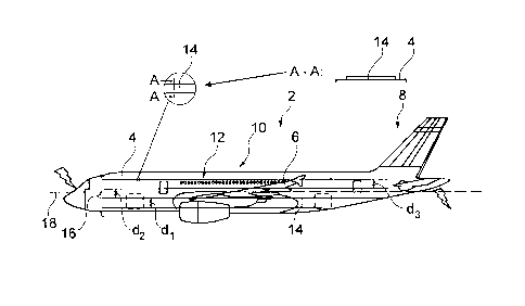
Fig. 1 shows an aircraft 2 having an aircraft fuselage 4, a wing assembly 6
and a tail assembly
8. By way of example, the aircraft 2 is embodied as a passenger aircraft,
which can be subject
to lightning strikes in corresponding weather conditions.
Very schematically, a lightning protection device 12 is arranged on a surface
structure 10,
said device extending by way of example over significant parts of the aircraft
2. The lightning
protection device 12 has a plurality of electrically conductive elements 14,
which are
embodied in the manner of bands. In a detail view and a partial section, the
flat, band-type
structure is apparent.
By way of example, there is a first group 16 of electrically conductive
elements 14, which
extend along a longitudinal axis 18 of the aircraft 2. In this case, the
conductive elements 14
could extend parallel to the longitudinal axis 18 or could extend at least
substantially along
the longitudinal axis 18. This can mean that the significant extent of the
conductive elements
14 is in the longitudinal direction 18. Overall, angles of up to 25 degrees
relative to the
longitudinal axis are possible, for example. However, these angles can be even
larger locally
if required.
There are spacings dl, d2, d3 etc. between the individual conductive elements
14. The
spacings dl to d3 can differ from one another, depending on the demands on
lightning
protection. In regions of the surface structure 10 in which greater lightning
protection is
required, the corresponding spacing dl, d2 or d3 can be reduced, while it can
be increased in
other regions.
9
CA 3043815 2019-05-21
Fig. 2a shows, by way of example, two mutually spaced and mutually parallel
conductive
elements 14, which have a meandering course. Both elements 14 can each be
surrounded by
rectilinear envelope curves 15 touching the edge of the elements 14. By way of
example,
these envelope curves extend parallel to one another and could extend parallel
to the
longitudinal axis 18. As explained above, the envelope curves 15 could also
enclose an angle
of up to 25 with the longitudinal axis 18.
Fig. 2b shows another example of a conductive element 14, which is arranged in
the vicinity
of a window 17. The conductive element 14 could, for instance, have a bend 19,
which runs
around the window 17. Overall, however, the conductive element could extend
along the
longitudinal axis 18.
Fig. 3 shows an upper side of the aircraft 2 by way of example in the upper
half of the plane
of the drawing and shows a lower side of the aircraft 2 by way of example in
the lower half of
the plane of the drawing. Here, in addition to the first group 16 of
electrically conductive
elements 14, a second group 20 of electrically conductive elements 14, which
extend along a
circumferential direction of the aircraft fuselage 4, is furthermore provided.
Consequently, the
elements 14 extend around the aircraft fuselage 4 and in part also regions of
the wing
assembly 6 or of a wing root 25. The elements of this second group 20 have a
spacing el , e2
and e3 with respect to one another. The spacing e 1, e2 or e3 between the
individual elements
14 can likewise be performed in order to adapt the lightning protection to
local requirements.
The second group is situated predominantly in a region of the surface
structure 10 of the
fuselage 4 which also includes the wing root 25.
As can be seen from Fig. 3, the conductive elements 14 of the second group 20
can overlap
with those of the first group 16, resulting in a multiplicity of points of
intersection. At these
points, the elements of the overlapping groups 16 and 20 can be connected
conductively to
one another in order to produce current flow over a larger area. This could
then reduce the
expenditure on repairs after a lightning strike.
CA 3043815 2019-05-21
As an alternative, the points of intersection could be of insulating design in
order to
concentrate the current flow. It is thereby possible to reduce the expenditure
on production
and maintenance.
Furthermore, two third groups 21, which extend on the wing assembly 6, are
shown. By way
of example, the individual electrically conductive elements 14 each extend
over the entire
span of one half of the wing assembly 6 and each touch a wing assembly tip 23.
As shown
here, the conductive elements 14 could extend parallel to individual chord
lines and, at the
same time, could each follow a relative chord length. In a region at the wing
root 25, the
conductive elements 14 of the third group 21 can coincide with those of the
second group 20
or can be supplemented thereby. Consequently, points of intersection with
elements 14 of the
first group 16 and of the second group 20 could also arise, and these can be
of insulating or
electrically conductive design according to criteria mentioned above.
Fig. 4 shows a cross section of the aircraft fuselage 4 in a very schematic
illustration. It should
once again be noted here that the outer surface of the aircraft fuselage 4 is
not stepped or
undulating but is shaped in an aerodynamically favourable and harmonious way,
in particular
smoothly. The illustration in Fig. 4 is merely intended to indicate that the
material thickness
of the aircraft fuselage 4 can vary and that electrically conductive elements
14 can be
mounted at different positions on the aircraft fuselage.
The aircraft fuselage 4 has an outer skin 22, which has different material
thicknesses. In a
lower section 24, the material thickness of the fuselage skin 22 is greater
than, for example, in
an upper section 26. To adapt to the variable material thickness, the selected
spacing dl to
d12 of the individual conductive elements 14 can be smaller than on a lower
side 24. Here, the
spacings between the elements 14 are denoted by dl to d12 for each side of the
fuselage 4,
wherein dl denotes the spacing between an uppermost conductive element 14 and
the element
14 which follows it in the circumferential direction, while d12 stands for the
spacing between
the two lowermost elements 14.
By way of example, it is shown that spacings d8, d9, d10, dl 1 and d12 belong
to the lower
fuselage half 24 and are significantly larger than the spacings dl to d7 in
the upper fuselage
11
CA 3043815 2019-05-21
half 26. Moreover, a plurality of electric bus lines (busbars) 28 is arranged
radially on the
inside on the upper side 26, by way of example on both sides of the aircraft
fuselage 4,
wherein the spacings d3, d4 and d5 are significantly smaller in a region
situated directly
radially on the outside than in all other regions. Damage to the bus lines 28
caused by
lightning strikes can thereby be limited to the greatest extent possible.
For the sake of completeness, it should be noted that "having" does not
exclude any other
elements or steps and "a" or "an" does not exclude a multiplicity. It should
furthermore be
noted that features which have been described with reference to one of the
above embodiment
examples can also be used in combination with other features of other
embodiment examples
described above. Reference signs in the claims should not be regarded as
restrictive.
12
CA 3043815 2019-05-21