Note: Descriptions are shown in the official language in which they were submitted.
111
- 1 -
CASKET ORNAMENT ATTACHMENT MECHANISM
RELATED APPLICATIONS
[0001] N/A
FIELD OF THE INVENTION
[0002] This invention relates generally to caskets, and more particularly
to
mechanisms for attaching ornaments to caskets, urns, and other funerary
articles.
BACKGROUND OF THE INVENTION
[0003] It is known to attach decorative ornaments to caskets to
"personalize" the
casket to the deceased. Examples of mechanisms for attaching ornaments to the
exterior of a casket, for example to the corners of the casket shell, are
shown in, for
example, the assignee's US Patent Nos. 6,591,466, 6,928,706, 7,591,052, and
7,698,792, all hereby incorporated by reference herein as if fully set forth
in their
entireties. Examples of mechanisms for attaching ornaments to the interior of
a
casket, for example to the cap panel mounted in the underneath side of the
head end
casket cap, are shown in, for example, the assignee's US Patent No. 8,220,119,
hereby incorporated by reference herein as if fully set forth in its entirety.
[0004] One embodiment of the ornaments for attachment to the cap panel
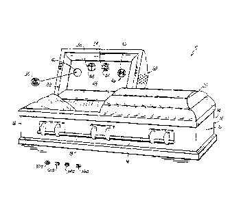
disclosed in the '119 patent utilizes one or more magnets mounted on the rear
side of
the "medallion" style ornament for magnetically attaching the medallion to a
magnetic
CA 3043916 2019-05-22
- 2 -
cap panel. On the other hand, the casket corner ornaments of the '466, '706,
and
'792 patents utilize fasteners with heads, mounted on the rear side of the
ornament,
which are secured in L-shaped keyhole slots in the casket shell corners.
[0005] It was desirable to be able to utilize the medallion ornaments with
magnets
thereon with the casket shell L-shaped keyhole slots so that the medallions
can also
be mounted on the casket shell corners.
[0006] To that end, one solution is shown in the assignee's US Patent No.
8,387,219, hereby incorporated by reference herein as if fully set forth in
its entirety.
The '219 patent discloses a casket comprising a casket shell and a casket lid
closeable on the shell. A mounting plate is mounted to the shell. The plate
includes
at least one keyhole groove therein. A medallion casket ornament has at least
one
magnet mounted on its rear side. A magnetic adapter plate has at least one
fastener
with a head thereon mounted on its rear side. The adapter plate is removably
secured to the shell by inserting the head of the fastener in the keyhole
groove in the
mounting plate and seating the head of the fastener in the keyhole groove. The
casket ornament is removably secured to the shell by positioning the at least
one
magnet of the ornament on the adapter plate. See Prior Art Fig. 1.
[0007] An improvement to the attachment mechanism shown in Prior Art Fig. 1
is
shown in Prior Art Fig. 2. Whereas in Prior Art Fig. 1 the entire adapter
plate is
fabricated of ferrous material, in the improved attachment mechanism shown in
Prior
Art Fig. 2 the adapter plate is injection molded of plastic. Two rearward
facing
CA 3043916 2019-05-22
- 3 -
fasteners, each with a head thereon, are molded into the plastic adapter
plate. Three
forward facing ferrous washers are also molded into the plastic adapter plate.
Each
washer is positioned in one of three recesses, also molded into the plastic
adapter
plate.
[0008] The assignee's US Patent Nos. 8,555,471 and 8,756,774, hereby
incorporated by reference herein as if fully set forth in their entirety,
disclose custom
medallions that can be fabricated on site by a funeral director with family
member-
supplied or funeral director-supplied photos, artwork, or other images.
However, due
to the fact that these custom medallions are hand assembled, the photo,
artwork, or
other image may not be "plumb" relative to the three magnets of the medallion,
thus
resulting in a canted photo, image, or other artwork once the custom medallion
is
attached to the adapter plate shown in Prior Art Fig. 2, which is mounted to
the
casket shell.
[0009] Accordingly, further improvement is desired.
SUMMARY OF THE INVENTION
[0010] In one aspect a casket comprises a casket shell, a casket lid
closeable on
the shell, at least one keyhole groove in the shell, a medallion casket
ornament
having a rear side, the ornament including at least one magnet mounted on the
rear
side, and an adapter plate having at least one rearward facing fastener with a
head
thereon and having a forward facing annular magnetic plate. The adapter plate
is
removably secured to the shell by inserting the head of the fastener in the
keyhole
CA 3043916 2019-05-22
- 4 -
groove and seating the head of the fastener in the keyhole groove. The
ornament is
removably secured to the shell by positioning the at least one magnet of the
ornament on the annular magnetic plate. The ornament is plumbed by rotating
the
ornament relative to the adapter plate until the ornament is plumb.
[0011] The
shell can include two vertically spaced keyhole grooves therein, each
being L-shaped, and the adapter plate can include two vertically spaced
fasteners.
The ornament can include three magnets mounted on the rear side, the three
magnets being equally spaced around a circumference of the ornament. The
adapter plate can be injection molded of plastic. The fasteners can be
metallic, and
the fasteners and the annular magnetic plate can be molded into the adapter
plate.
The adapter plate can be circular, include a forwardly projecting flange
around a
circumference thereof, and include a forwardly projecting circular feature
located
centrally thereof, and the annular magnetic plate can be recessed relative to
the
flange and the circular feature thereby forming an annular track, whereby
rotating the
ornament relative to the adapter plate causes the three magnets to slide on
the
annular magnetic plate while being retained in the track. The adapter plate
and
ornament can be generally circular, with the diameter of the adapter plate
being less
than the diameter of the ornament. The adapter plate and ornament can be
generally disk-shaped. The adapter plate can include an edge scallop that
facilitates
grasping the periphery of the adapter plate to separate the adapter plate from
the
ornament.
CA 3043916 2019-05-22
- 5 -
[0012] In another aspect, a funerary receptacle for containing remains of a
deceased comprises a container adapted to contain the remains, a lid closeable
on
the container, at least one keyhole groove in the container, a medallion
funerary
receptacle ornament having a rear side, the ornament including at least one
magnet
mounted on the rear side, and an adapter plate having at least one rearward
facing
fastener with a head thereon and having a forward facing annular magnetic
plate.
The adapter plate is removably secured to the container by inserting the head
of the
fastener in the keyhole groove and seating the head of the fastener in the
keyhole
groove. The ornament is removably secured to the container by positioning the
at
least one magnet of the ornament on the magnetic annular plate. The ornament
is
plumbed by rotating the ornament relative to the adapter plate until the
ornament is
plumb.
[0013] The container can be either a casket shell or a cremation urn.
[0014] In another aspect, a funerary article comprises a mounting surface
including at least one keyhole groove therein, a medallion funerary article
ornament
having a rear side, the ornament including three circumferentially equally
spaced
magnets mounted on the rear side, and a plastic adapter plate having at least
one
rearward facing metallic fastener with a head thereon and having a forward
facing
annular magnetic plate. The adapter plate is removably secured to the mounting
surface by inserting the head of the fastener in the keyhole groove in the
mounting
surface and seating the head of the fastener in the keyhole groove. The
ornament is
removably secured to the adapter plate by positioning the magnets of the
ornament
CA 3043916 2019-05-22
- 6 -
on the annular magnetic plate. The ornament is plumbed by rotating the
ornament
relative to the adapter plate until the ornament is plumb.
[0015] The accompanying drawings, which are incorporated in and constitute
a
part of this specification, illustrate embodiments of the invention and,
together with
the summary of the invention given above, and the detailed description of the
drawings given below, serve to explain the principles of the present
invention.
BRIEF DESCRIPTION OF THE DRAWINGS
[0016] Fig. 1 is a disassembled perspective view of one prior art adapter
plate for
attaching a medallion ornament to a casket corner.
[0017] Fig. 2 is a disassembled perspective view of another prior art
adapter plate
for attaching a medallion ornament to a casket corner.
[0018] Fig. 3 is a perspective view of a casket with recesses formed in the
cap
panel each of which is adapted to receive a medallion ornament therein for
display.
[0019] Fig. 4 is a perspective view of a magnetic casket cap panel adapted
to
have medallion ornaments having magnets on the backs thereof placed thereon
for
display.
[0020] Fig. 5A is a disassembled perspective view of an adapter plate
embodying
the principles of the present invention for attaching a medallion ornament to
a casket
corner.
CA 3043916 2019-05-22
- 7 -
[0021] Fig. 5B is an assembled perspective view of the adapter plate and
medallion ornament of Fig. 5A.
[0022] Fig. 6A is a disassembled front view of the adapter plate and
medallion of
Fig. 5A.
[0023] Fig. 6B is an assembled front view of the adapter plate and
medallion of
Fig. 6A with the medallion ornament out of plumb.
[0024] Fig. 6C is a view similar to Fig. 6B but with the medallion rotated
relative to
the adapter plate so that the medallion ornament is plumb.
[0025] Fig. 7A is a disassembled side cross-sectional view of the adapter
plate
and medallion ornament of Fig. 5A.
[0026] Fig. 7B is an assembled side cross-sectional view of the adapter
plate and
medallion ornament of Fig. 5A.
DETAILED DESCRIPTION OF THE DRAWINGS
[0027] Referring first to Fig. 3, a casket 10 has a shell 12 adapted to
receive the
remains of a deceased having a pair of side walls 14, 14, a pair of end walls
16, 16,
and a bottom wall 18, and a cap 20 closable on the shell 12. The casket may
have a
pair of caps or a single cap the full length of the casket. Cap 20 has an
ornamental
dish assembly 22 mounted to an underside of the cap 20. The dish assembly 22
includes a cap panel 24. At least one medallion 30 is mounted on either an
interior
CA 3043916 2019-05-22
- 8 -
surface or an exterior surface of either the shell 12 or cap 20. The medallion
30 has
text/or graphics representing a life aspect of the deceased, for example,
Father,
Brother, Husband, Lawyer, Christian, Hunter, Fisherman, etc. and may be
fabricated
of a metallic or non-metallic material.
[0028] The medallion 30 can be mounted in a recess 40 in the cap panel 24,
for
example. As another example, the medallion 30 can be mounted in a recess in an
exterior surface of the cap 20. The recess 40 can have a circumferential shape
that
matches a circumferential shape of the medallion 30. The circumferential
shapes of
the recess 40 and the medallion 30 can be circular, for example, as
illustrated.
[0029] Four medallions 30, 32, 34, 36 can be mounted in respective recesses
40,
42, 44, 46. The recesses 40, 42, 44, 46 can be formed in the cap panel 24 such
that
the medallions 30, 32, 34, 36 mounted therein are arranged in an arcuate
pattern, as
shown in FIG. 3. The medallion(s) can be mounted in the recess with a fastener
such as double sided tape, hook and loop fastener, adhesive, magnets, or
simply by
a press-fit. Outfitting the casket 10 with plural themed medallions 30, 32,
34, 36
permits plural life roles of the deceased to be displayed and celebrated
instead of
only a single life role per current casket personalization.
[0030] Reduced scale medallions 30a, 32a, 34a, 36a can be supplied or
provided
with the casket 10. The reduced scale medallions 30a, 32a, 34a, 36a correspond
to
the full size medallions 30, 32, 34, 36 in that they have substantially the
same shape,
text, and graphics of the full size medallions 30a, 32a, 34a, 36a. However,
the
CA 3043916 2019-05-22
- 9 -
reduced scale medallions 30a, 32a, 34a, 36a are sized to fit in a pocket of an
article
of clothing worn by a surviving loved one of the deceased. For example, the
reduced
size medallions can be about the size and shape of a coin permitting easy
carry in a
pocket, purse, etc.
[0031] In use, the funeral director displays the deceased in a casket 10
having at
least one medallion 30 mounted as described above. Subsequent to the viewing,
the
funeral director presents the substantially identical reduced size medallion
30a to the
survivor of the deceased for carry in a pocket or purse as a keepsake and
reminder
of the life of the deceased. Prior to the funeral director presenting the
medallion 30a
to the survivor, it can be engraved on its rear side with the name and birth
and death
dates of the deceased.
[0032] Referring now to Fig. 4, the dish assembly 22 is constructed in such
a way
as to permit medallions 30 to be placed anywhere on the cap panel 24. In this
embodiment each of the medallions has one or more magnets 31 on a rear side
thereof. The cap panel 24 is fabricated from a sheet of cardboard or chipboard
25
over which is placed a sheet of magnetic material 27, for example a ferrous
material
such as steel. The sheet of magnetic material 27 is then covered with a sheet
of
decorative material 29. Since the entire surface area of the cap panel 24 is
magnetic
material, medallions 30 can be placed anywhere within the surface area of the
cap
panel 24, i.e. they do not have to be placed within a designated recess. This
permits
more freedom in placing and arranging medallions as desired by the funeral
director,
and/or family, friends, and/or loved ones of the deceased.
CA 3043916 2019-05-22
- 10 -
[0033] Referring to Figs. 5A-7B, a medallion casket ornament 30 includes at
least
one magnet 31, and preferably three magnets 31 equally spaced around a
circumference of the ornament 30, mounted on a rear side of the ornament 30. A
plastic injection molded adapter plate 60 has a pair of metallic vertically
spaced
fasteners 62 molded into a rear side of the adapter plate 60. Each fastener 62
includes a head 64 thereon. Adapter plate 60 also has an annular magnetic
plate 66
molded into a front side of the plate 60. The annular magnetic plate 66 can be
fabricated of a ferrous metal, for example a ferrous material such as steel,
or other
magnetic metal or material which is attracted by a magnet, or annular magnetic
plate
66 can itself be a magnet. Accordingly, the term "magnetic plate" shall be
construed
to embrace all such meanings.
[0034] The adapter plate 60 is removably secured to the casket shell by
inserting
the heads 64 of fasteners 62 in the casket shell keyhole grooves and seating
the
heads 64 of the fasteners 62 in the keyhole grooves as is known (Fig. 1). The
ornament 30 is then removably secured to the casket shell by positioning the
magnets 31 on the magnetic annular plate 66. Finally, to plumb the image on
the
ornament 30, the ornament 30 is rotated relative to the adapter plate 60 until
the
image on the ornament 30 is plumb.
[0035] The adapter plate 60 includes a forwardly projecting edge, rim, or
flange 70
around a circumference of the plate 60. The adapter plate 60 also has a
forwardly
projecting circular feature 72 located centrally of the plate 60. The annular
magnetic
plate 66 is recessed relative to the flange 70 and the circular feature 72.
The annular
CA 3043916 2019-05-22
-11 -
magnetic plate 66, flange 70, and circular feature 72 thus form an annular
track 74 in
which the magnets 31 are received. Thus, once ornament 30 is removably secured
to adapter plate 60 by placing magnets 31 into contact with magnetic annular
plate
66, the magnets 31 are positioned within the annular track 74. Rotating the
ornament 30 relative to the adapter plate 60 causes the magnets 31 to slide on
the
annular magnetic plate 66 while being retained in the track 74. In this way
the plumb
of the ornament 30 may be adjusted while conveniently keeping the ornament 30
centered on the adapter plate 60.
[0036] One particularly desirable geometry for the ornament 30 is generally
circular and generally disk-shaped, in which case the adapter plate 62 can
also be
generally circular and generally disk-shaped. The adapter plate 62 will
generally be
of a smaller diameter than the ornament 30 so as not to show.
[0037] It will of course be appreciated that the ornament attachment
mechanism
of this invention can be used in conjunction with cremation urns that are
similarly
equipped with keyhole grooves.
[0038] The adapter plate 60 also includes an edge scallop feature 76 at a
periphery thereof that facilitates grasping the periphery of the adapter plate
60 to
separate the adapter plate 60 from the ornament 30.
[0039] The invention herein can be utilized not only with casket shell
corners and
urns, but with other funerary articles that employ keyhole groove and fastener
with
head attachment of ornaments, as well. For example, the invention can be
utilized
CA 3043916 2019-05-22
- 12 -
with the casket cap dish assemblies of US Patents 7,657,981, 7,584,529,
7,159,287,
and 6,715,190, all of which are hereby incorporated by reference herein as if
fully set
forth in their entirety. The invention can also be utilized with the display
plaque of US
Patent 6,557,222, and with the display pedestal of US Patent 6,691,385, both
of
which are hereby incorporated by reference herein as if fully set forth in
their entirety.
[0040]
The various embodiments of the invention shown and described are merely
for illustrative purposes only, as the drawings and the description are not
intended to
restrict or limit in any way the scope of the claims. Those skilled in the art
will
appreciate various changes, modifications, and improvements which can be made
to
the invention without departing from the spirit or scope thereof. The
invention in its
broader aspects is therefore not limited to the specific details and
representative
apparatus and methods shown and described. The invention resides in each
individual feature described herein, alone, and in all combinations of any and
all of
those features. Departures may therefore be made from such details without
departing from the spirit or scope of the general inventive concept.
Accordingly, the
scope of the invention shall be limited only by the following claims and their
equivalents.
CA 3043916 2019-05-22