Note: Descriptions are shown in the official language in which they were submitted.
t ,
CAA 03043968 2019-05-15
- I -
TENSIONING CABLE SPREADING DEVICE, TENSIONING CABLE
LUBRICATION DEVICE AND TENSIONING CABLE LUBRICATION METHOD
The present invention concerns a device for spreading a multi-stranded
tensioning cable, in particular steel tensioning cables. The invention further
concerns a device for lubricating a multi-stranded tensioning cable, in
particular a
steel tensioning cable. Moreover the invention concerns a method of spreading
a
multi-stranded tensioning cable, in particular a steel tensioning cable, and a
method of lubricating a multi-stranded tensioning cable, in particular a steel
tensioning cable.
Devices and methods of the above-indicated kind are necessary in
industry for preparing tensioning cables, in particular steel tensioning
cables, for
sheathing with plastic sheaths. In order to combat corrosion on the one hand
and
wear as a result of friction on the other hand a certain amount of lubricant,
in
particular grease, has to be provided between the strands of the tensioning
cable
as that is no longer possible subsequently, as soon as the plastic sheath has
been placed around the cable.
Generally known sheathing apparatuses which operate by means of
plastic extrusion are used for applying the plastic sheath.
Spreading the tensioning cable has proven to be a work-intensive and
time-intensive preparation step in the state of the art. Usually that is
effected by
the tensioning cable being spread out into the individual strands at its cable
end,
and by each of the strands being introduced into an individual feedthrough
opening in a spreading ring which has a number of individual feedthrough
openings, that is matched to the tensioning cable. That spreading ring is then
moved along the cable by the application of force or is held stationary and
the
cable is drawn through the spreading ring by the application of force. In the
spread condition it is possible for lubricant like for example grease to be
introduced into the interior of the tensioning cable.
A continuous mode of production however is not possible with the devices
and methods in the state of the art. At the beginning each cable has to be
- 2 -
manually inserted into the spreading ring. Cable groups which consist of two
tensioning cables and which are joined at the transitional locations, for
example
by means of clamping or welding, can generally not be processed in this way as
the spreading ring cannot be drawn over those junction locations or the cable
with the junction location cannot be pulled past the spreading ring.
On the application for which priority is claimed for the present application
the German Patent and Trade Mark Office searched the following state of the
art:
DE 20 2014 004 947 U1, DE 600 16 582 T2, and US 2 010 184 A.
Consequently the object of the invention is to develop a device of the kind
set forth in the opening part of this specification in such a way that the
disadvantages previously encountered in the state of the art are eliminated as
far
as possible. In particular the object of the invention is to provide a device
for
spreading a multi-stranded tensioning cable, with which spreading is
facilitated,
which in particular makes it possible to insert lubricant into the interior of
the
tensioning cable without having to thread in the start of the tensioning cable
and
which in addition in particular permits a continuous mode of production.
In a device for spreading a multi-stranded tensioning cable, in particular
steel tensioning cables, the object of the invention is attained with the
features
disclosed herein. It is proposed that the device has a main body having a
feedthrough opening for the entire tensioning cable, and a number of spreading
elements which are arranged radially movably in the main body and each have a
contour which is of a configuration tapering inwardly in the radial direction
for
engaging and producing a gap between respectively adjacent strands of the
tensioning cable. The invention makes use of the fact that the tensioning
cable in
accordance with this concept does not have to be frayed open at its cable end
into the individual strands, but the entire tensioning cable is introduced
into a
common feedthrough opening so that the spreading elements can act from the
exterior on the exposed strands of the tensioning cable. The invention makes
use of the realisation that large spacings between the strands of the
tensioning
cable are not required. Small gaps are already sufficient for introducing
lubricant
like for example grease. It is precisely those small gaps that can be produced
by
Date Recue/Date Received 2020-08-12
1 , CAA 03043968 2019-05-15
- 3 -
very slight displacement movements in a lateral direction in relation to the
radial
movement of the spreading elements, by the spreading elements encountering
the strands from the exterior, engaging into interstices between the strands
and
displacing the strands towards the side to such an extent that a small gap is
produced between the strands. According to the invention the term strand of
the
tensioning cable is used to denote both a wire and also a braid. According to
the
invention the term number of strands is used to denote a number including 1
and
a whole multiple of 1. Particularly preferably the device has 2, 3, 4 or 6
spreading
elements.
In a preferred embodiment the spreading elements are of a pin-shaped
configuration. Particularly preferably the spreading elements are
substantially
cylindrical spreading mandrels which at their radially inward end, relative to
the
feedthrough opening, have a point tip adapted for spreading.
In an alternative and equally preferred embodiment the spreading
elements each have a spreading roller mounted rotatably in a radially movable
piston. The radial mobility of the piston also relates to the feedthrough
opening.
The advantage of the spreading rollers lies in the reduced sliding friction
when
drawing the tensioning cable through the device for spreading the tensioning
cable.
In a further preferred embodiment the main body is mounted in the device
rotatably about an axis of rotation, at any event through a predetermined
angular
range, wherein the axis of rotation extends substantially parallel and in
particular
coaxial in relation to a feedthrough direction of the tensioning cable through
the
feedthrough opening. By virtue of easy rotatability of the main body it is
possible
to use even tensioning cables which are twisted in themselves and in which the
strands do not extend in a straight line but are twisted for example in a
spiral
shape. The main body then easily involves the rotational movement produced as
a consequence of the twist when the tensioning cable is drawn through the
feedthrough opening. Slight irregularities in the orientation of the strands
in the
case of otherwise substantially untwisted tensioning cables can also be
ensured
by the at least limited rotatability of the main body.
1 , CAA 03043968 2019-05-15
- 4 -
According to a preferred embodiment of the invention the spreading
elements are respectively arranged in the main body radially movably by means
of a thread. Screwing the spreading elements into the thread makes it possible
quite accurately to adjust how great the degree of spreading of the tensioning
cable is to be, as well as easily ensuring adaptation to different tensioning
cable
diameters. If the thread has a sufficiently low thread pitch, for example in
the
form of a self-locking thread, spontaneous displacement of the spreading
elements is also almost out of the question. As an additional safeguard it is
for
example possible to provide locking elements or other fixing mechanisms.
In a further preferred embodiment the spreading elements are
respectively actuated hydraulically or pneumatically. In preferred
configurations
the spreading elements each have a piston surface arranged in a piston
chamber, wherein the piston chamber can be respectively acted upon with a
fluid
pressure. For that purpose the piston chambers are preferably in fluid-
conducting
relationship to an in particular common control pressure line.
In a further preferred embodiment the spreading elements are each
electromagnetically actuated.
In a particularly preferably embodiment the spreading elements are
adapted to be respectively deflected by means of a wedge slider. Particularly
preferably the respective wedge sliders are arranged guided movably in the
feedthrough direction of the steel tensioning cable. The spreading elements
are
preferably moved inwardly or outwardly in the radial direction by rolling or
sliding
along the at least one wedge slider. Particularly preferably for that purpose
the
spreading elements have a rolling body or a slide surface which is in
operative
relationship with the wedge slider. The wedge sliders in turn are driven for
example mechanically, electromagnetically, pneumatically or hydraulically.
In a further aspect as mentioned in the opening part of this specification
the invention also concerns a device for lubricating a multi-stranded
tensioning
cable, in particular steel tensioning cables. The invention attains its object
by
proposing such a device comprising a feedthrough passage for the tensioning
cable, a lubricant passage which opens into the feedthrough passage and which
CA 030439,68 2019-05-15
- 5 -
is in fluid-conducting relationship with at least one pressure generator,
wherein a
device according to one of the above-described preferred embodiments is
associated with the lubricant passage.
In accordance with that aspect the invention enjoys the advantages of the
spreading device according to the invention for automated lubrication. In
particular it is no longer necessary for the cable to be previously spread
open
manually from the beginning of the cable by means of a conventional spreading
ring and for the first time automated continuous production of a lubricated
tensioning cable for feeding to a sheathing apparatus becomes possible.
In regard to the advantages and preferred embodiments of the device for
lubricating the cable attention is directed to the foregoing embodiments and
description.
Preferably the device for spreading the tensioning cable is arranged in the
feedthrough passage.
The at least one pressure generator is preferably adapted to convey
lubricant under an increased pressure through the lubricant passage into the
feedthrough passage. By filling the feedthrough passage in which particularly
preferably the spreading device is also arranged with increased pressure this
provides that the entire feedthrough passage is constantly filled with
lubricant.
In a further preferred embodiment the device has a first lubricant passage
arranged upstream of the spreading device and a second lubricant passage
arranged downstream of the spreading device. While the first lubricant passage
preferably serves to introduce lubricant into the feedthrough passage, which
is
then provided for penetrating into the spread tensioning cable, the second
lubricant passage is provided for introducing lubricant into the feedthrough
passage in order that the tensioning cable which is already lubricated in its
interior is also additionally lubricated on its exterior.
In a further preferred embodiment the device has a lubricant stripper
arranged at the outlet end of the feedthrough passage and dimensioned to strip
excess lubricant off and keep it in the feedthrough passage so that the
tensioning
CAA 03043968 2019-05-15
- 6 -
cable issues from the feedthrough passage from a defined lubricant film with a
mean outside lubricant diameter defined by the lubricant stripper.
The at least one pressure generator is particularly preferably adapted in
dependence on the conveyor speed of the tensioning cable through the
feedthrough passage to deliver a predetermined amount of lubricant through the
lubricant passage. Further preferably the at least one pressure generator is
adapted to deliver lubricant at a delivery rate in a region of about 25
g/metre of
tensioning cable or more, further preferably 50 g/metre of tensioning cable or
more, in particular in a region of 55 g/metre to 100 g/metre of tensioning
cable.
In a further aspect the invention concerns a method of spreading a multi-
stranded tensioning cable, in particular steel tensioning cables. The object
of the
invention is attained by proposing such a method including the steps:
- passing the tensioning cable through a feedthrough opening,
- moving a number of spreading elements radially inwardly within the
feedthrough opening so that the spreading elements
- engage between adjacent strands, and
- produce a gap between the adjacent strands.
The features described hereinbefore in relation to the two device aspects,
in particular in respect of their functional features, are at the same time
preferred
embodiments and configurations of the method according to the invention for
spreading a tensioning cable. In that respect attention is directed to the
foregoing
description.
In a further aspect the invention concerns a method of lubricating a multi-
stranded tensioning cable, in particular steel tensioning cables. The object
of the
invention is attained by the invention proposing such a method including the
steps: passing the tensioning cable through a feedthrough passage, delivering
lubricant on to the tensioning cable within the feedthrough passage, and
spreading the tensioning cable before delivery of the lubricant, wherein
spreading is effected in accordance with one of the above-described and
preferred embodiments. The lubrication method according to the invention also
CA 03043968 2019-05-15
- 7 -
makes use of the embodiments and advantages described hereinbefore with
reference to the devices according to the invention.
In a further aspect the invention concerns the use of a device comprising
a main body having a feedthrough opening for the entire tensioning cable, and
a
number of spreading elements which are arranged radially movably in the main
body and which are of a contour of a configuration tapered inwardly in the
radial
direction for spreading a multi-stranded tensioning cable, in particular steel
tensioning cables, wherein the spreading elements engage between respectively
adjacent strands of the tensioning cable and produce a gap between the
adjacent strands.
The invention is described in greater detail hereinafter with reference to
the accompanying Figures by means of two preferred embodiments. In the
Figures:
Figure la shows a diagrammatic view of a lubricating and spreading
device according to a first preferred embodiment,
Figure lb shows a diagrammatic view of a lubricating and spreading
device according to a second preferred embodiment,
Figure 2 shows a diagrammatic perspective partial view of the lubricating
and spreading device of Figure lb,
Figure 3 shows a further perspective view of a part of the lubricating and
spreading device of Figure 2, and
Figure 4 shows a complete diagrammatic view of the lubricating and
spreading device shown in the previous Figures.
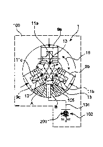
Figure la shows a lubricating device 100 for lubricating a steel tensioning
cable 301 comprising a plurality of strands. The lubricating device 100 has a
spreading device 1 for spreading the multi-stranded steel tensioning cable
301.
The spreading device 1 has a main body 3 in which a number of spreading
elements 5a, b, c are radially movably arranged. In this respect radial
mobility
relates to a feedthrough opening 7 in the main body 3. The spreading elements
5a, b, c are therefore movable substantially towards and away from the centre
of
the feedthrough opening 7. On their side which is radially inward relative to
the
CA 03043968 2019-05-15
- 8 -
feedthrough opening 7 the spreading elements 5a, b, c are of a tapered contour
adapted to engage between adjacent strands of the steel tensioning cable 301
and to displace same laterally in such a way, as indicated by small arrows,
that a
small gap 13 is produced between the adjacent strands of the steel tensioning
cable 301. Lubricant 200 is pressed through that narrow gap which is in a
lubrication plane B downstream of the spreading location (shown in the section
plane A) through a lubricating passage 101, into a feedthrough passage 105
which is preferably coaxial with the feedthrough opening 7 of the spreading
device 1. That is preferably effected by means of a lubricant supply having a
pressure generator 103 which is preferably controlled electronically and which
in
dependence on the conveyor speed of the steel tensioning cable 301 through the
feedthrough passage 105 delivers a predetermined delivery rate of lubricant
200.
The main body 3 is preferably rotatable or pivotable in the direction of the
arrows 15, at least by a given angular amount. The axis of rotation is
preferably
the designated central axis of the feedthrough opening 7 or feedthrough
passage
105.
The second embodiment shown in Figure lb is structurally very similar to
the embodiment of Figure la. Identical or functionally identical components
are
denoted by the same references. Unlike the embodiment of Figure la in which
the spreading elements 5a-b are of a pin-shaped configuration the spreading
elements 9a-c in the second embodiment respectively have spreading rollers
1 1 a-c mounted rotatably in the piston-shaped spreading elements 9a-c. The
displacement operation however is substantially the same. In a spreading plane
A the spreading elements 1 1 a-c are moved radially inwardly whereby they
engage between adjacent strands of the steel tensioning cable 301 and displace
the adjacent strands respectively in the direction of the small arrows so that
respective gaps 13 are formed between the adjacent strands, through which
gaps lubricant 200 can then be introduced through a lubricant passage 101 in
an
adjacent lubrication plane B.
The spreading elements 5a-c and 9a-c are preferably actuated
hydraulically or pneumatically, or electromagnetically. Alternatively the
spreading
. CA 03043968 2019-05-15
=
- 9 -
elements 5a-c and/or 9a-c are radially movable mechanically by means of
screwthread displacement.
Figures 2 and 3 respectively show sectional views of the lubricating and
spreading device. For the sake of simplicity here the spreading elements 9a-c
are respectively formed in accordance with the embodiment of Figure lb. The
specific description is to be interpreted in such a way that, instead of the
configuration shown in Figure 1 b, it is also possible to provide the
spreading
device of Figure la in the arrangement shown in Figures 2 to 4.
Figure 2 shows a partial section through the spreading device 1. The
feedthrough passage 105 and the feedthrough opening 7 in the main body 3 are
oriented coaxially in relation to the longitudinal axis A. The direction of
travel of
the tensioning cable is indicated by the arrow L. Particular attention is
applied in
Figure 2 to actuation of the spreading elements (spreading elements 9a, b).
Arranged at the spreading elements 9a, b are respective rolling bodies 17
which
are in operative relationship with a wedge surface 19. The wedge surface 19 is
provided on a cylindrical hollow body 22 which is movable with a translatory
movement in the direction of the arrow P1, substantially parallel to the axis
A. By
displacement of the hollow body 22 and the associated wedge surface 19 in the
direction of the arrow P1 the rolling bodies 17 are moved substantially
radially
towards the axis A in the direction of the arrow P2. The movement of the
hollow
body 22 is triggered by a lever 21 provided on the spreading device 1 (see
below
in relation to Figure 3).
The spreading device 1 has a tensioning cable inlet side 25 and an
oppositely arranged tensioning cable outlet side 27. Fitted to the housing of
the
spreading device 1 on the inlet side 25 is a flange in which there is an
intake
opening 23 for the feed of lubricant 200 into the feedthrough passage 105. The
entire interior, that is to say the feedthrough passage 105 and the
feedthrough
opening 7, can be filled with lubricant 200 by means of that intake opening
23.
The spreading device further has a manifold 31 which is in fluid-
conducting communication with the feedthrough passage 105 and which can be
CA 03043968 2019-05-15
- 10 -
opened and closed by means of a shut-off element 29. Lubricant can be
selectively let out of the feedthrough passage 105 by means of that manifold.
As can further be seen from Figure 3 the lever 21 which represents the
mechanical drive for the spreading elements (indicated at 9a, b) is movably
guided in a sliding guide 33. The lever 21 is pivotable from a first starting
position
35 into a second starting position 37. The first starting position 35
represents an
open position in which the tensioning cable is passed substantially unimpeded
through the feedthrough passage while the spreading elements in the second
starting position 37 are disposed in a spreading position, penetrate into the
tensioning cable and spread it. The sliding guide 33 is of a spiral
configuration
with respect to the axis A so that the lever position in the second starting
position
37 is rotated through an angle alpha relative to the first starting position
35 and is
displaced by a displacement x in the direction of the axis A. That
displacement
corresponds to the movement of the wedge surface 19 (Figure 2) which in
dependence on the angle of the wedge surface results in a radial movement of
the spreading elements (9a, b).
Figure 4 shows by way of example a diagrammatic view of the complete
lubricating device 100. The lubricating device 100 has an entry 201 for the
feed
of lubricant 200. The entry 201 is connected in fluid-conducting relationship
to
the first lubricant passage 101 (see Figures 1a, b) and a lubricant passage
102.
Preferably at least one pressure generator is interposed as part of the
lubricant
discharge device. In the present embodiment a first pressure generator 103 and
a second pressure generator 104 are provided for the two lubricating passages
101 and 102. With the two pressure generators 103, 104 it is possible to
predetermine the pressure of the first lubricant passage 101 independently of
the
pressure of the second lubricant passage 102.
While the first lubricant passage 101 feeds lubricant into the feedthrough
passage 105 (Figures 2 and 3) upstream of the spreading device 1 the second
lubricant passage 102 is arranged downstream of the spreading device 1 and
feeds lubricant subsequently from the exterior into the feedthrough passage
105.
In particular the proportion of lubricant which was supplied by means of the
CA 03043968 2019-05-15
11 -
second lubricant passage 102 contributes to lubricating the tensioning cable
301
at its periphery. Excess lubricant is removed from the tensioning cable 301 by
means of a stripper 107 arranged at the outlet end at the lubricating device
100
so that on issuing from the lubricating device 100 the tensioning cable 301
has a
lubricant film of defined thickness.