Note: Descriptions are shown in the official language in which they were submitted.
I
Bone cement applicator with retractable mixing rod and method for production
of a bone
cement
Description
The invention relates to a bone cement applicator for storage and mixing of a
bone cement powder
and a monomer liquid as well as for applying a pasty bone cement mixed
together from the bone
cement powder and the monomer liquid. The invention also relates to a method
for production of a
bone cement using said bone cement applicator.
The subject matter of the invention is a bone cement applicator for storage,
mixing, and application
of bone cement. The bone cement applicator is preferably implemented in the
form of a closed
prepack mixing system with an integrated extrusion device. The bone cement
applicator is
preferably well-suited and/or intended for arthroplasty, vertebroplasty, and
kyphoplasty. Methods
for the mixing and application of polymethylmethacrylate bone cement are
proposed for this
purpose as well.
Polymethylmethacrylate (PMMA) bone cements are based on the pioneering work of
Sir Charnley
(Charnley, J.: Anchorage of the femoral head prosthesis of the shaft of the
femur. J. Bone Joint
Surg. 42 (1960) 28-30). Conventional PMMA bone cements consist of a liquid
monomer component
and a powder component. The monomer component generally contains the monomer,
methylmethacrylate, and an activator (N,N-dimethyl-p-toluidine) dissolved
therein. The powder
component, also called bone cement powder or bone cement powder, comprises one
or more
polymers that are produced through polymerisation, preferably suspension
polymerisation, based
on methylmethacrylate and co-monomers, such as styrene, methylacrylate or
similar monomers, a
radiopaquer, and the initiator, dibenzoylperoxide. Mixing the powder component
and the monomer
component, swelling of the polymers of the powder component in the
methylmethacrylate
generates dough that can be shaped plastically and is the actual bone cement
or bone cement
.. dough. During the mixing of powder component and monomer component, the
activator, N,N-
dimethyl-p-toluidine, reacts with dibenzoylperoxide while forming radicals.
The radicals thus formed
trigger the radical polymerisation of the methylmethacrylate. Upon advancing
polymerisation of the
methylmethacrylate, the viscosity of the bone cement dough increases until the
bone cement dough
solidifies.
CA 3044592 2019-05-29
2
PMMA bone cements can be mixed by mixing the bone cement powder and the
monomer liquid in
suitable mixing beakers with the aid of spatulas. This can lead to air bubbles
being enclosed in the
bone cement dough, which can have a negative effect on the mechanical
properties of the cured
bone cement.
A large number of vacuum cementing systems has been described for preventing
air inclusions in
bone cement dough of which the following shall be specified here for exemplary
purposes: US 6
033 105 A, US 5 624 184 A, US 4 671 263 A, US 4 973 168 A, US 5 100 241 A, WO
99/67015 Al,
EP 1 020 167 A2, US 5 586 821 A, EP 1 016 452 A2, DE 36 40 279 Al, WO 94/26403
Al, EP 1
005 901 A2, EP 1 886 647 Al, US 5 344 232 A. Said mixing systems contain, for
mixing of the
cement components, a mixing rod that can be operated manually from outside and
has mixing
vanes as mixers attached to it. External vacuum pumps are required for
generation of the vacuum.
Said vacuum pumps are generally driven by compressed air and generate a vacuum
according to
the Venturi principle. Manually driven extrusion devices are used for
extrusion of the mixed bone
cement from the cartridges. Said extrusion devices can be connected reversibly
to the cartridges
for extrusion of the cement dough. Following the extrusion process, the
extrusion devices are
separated from the cartridges, cleaned, and re-sterilised. The spent
cartridges are discarded.
Cementing systems, in which both the bone cement powder and the monomer liquid
are already
packed in separate compartments of the mixing devices and are mixed with each
other in the
cementing system only right before application of the cement, are a
development of cementing
technology. Said closed full-prepacked mixing devices have been proposed in EP
0 692 229 Al,
DE 10 2009 031 178B3, US 5 997 544 A, US 6 709 149 B1, WO 00/35506 A1, EP 0
796 653 A2,
and US 5 588 745 A.
Patent DE 10 2009 031 178 B3 discloses a storage and mixing device as a full-
prepacked mixing
device, in which the starting components required for the production of the
bone cement are stored
already in the storage and mixing device and can be combined and mixed in the
storage and
mixing device. The storage and mixing device comprises a two-part dispensing
plunger for closing
a cement cartridge. A combination of a gas-permeable sterilisation plunger and
a gas-impermeable
sealing plunger is used in this context. This principle of a closed vacuum
mixing system is
implemented in the closed cementing system, PALACOSO PRO, made and distributed
by Heraeus
Medical GmbH. For the monomer transfer and the mixing in a vacuum, an external
vacuum pump is
CA 3044592 2019-05-29
3
required that is usually driven by compressed air. Likewise, a separate
manually operable extrusion
device is used for extruding the mixed cement dough.
- DE 10 2016 121 607 Al proposes a full-prepacked mixing system with a
cartridge containing a
bone cement powder for production of a bone cement. A dispensing plunger is
provided in the
cartridge and a receptacle containing a monomer liquid container is arranged
downstream from the
cartridge. A dispensing plunger is situated on the rear side of the receptacle
and can be used to
crush the monomer liquid container and to extrude the monomer liquid from the
receptacle into the
cartridge. This system involves no manual mixing of the starting components by
means of a mixer.
In the vacuum mixing systems with mixer referred to thus far, the mixing of
the cement components
must be followed by the mixing rod having to be broken off or pulled out of
the mixing system
before application of the bone cement. Accordingly, the known methods and
devices are
disadvantageous in that the process of breaking off the mixing rod may be
associated with leakage
of the bone cement applicator and in that the processes of breaking off and
pulling out the mixing
rod are always required as additional working steps. Moreover, the broken off
mixing rod litters the
OR theatre as another separate part that needs to be discarded. Bone cement
applicators without
mixer require much effort for the bone cement to be mixed sufficiently.
Moreover, it is also possible
that parts of the bone cement are not mixed sufficiently. These need to be
removed or retained or
there may be an adverse effect on the quality of the bone cement.
It is the object of the invention to develop a bone cement applicator for
storage, mixing, and
application of polymethylmethacrylate bone cement by means of which the
disadvantages of the
prior art can be overcome. The bone cement powder and the monomer liquid are
to be stored in
separate compartments in said bone cement applicator before being mixed. The
monomer transfer
from the monomer liquid container into the bone cement powder shall take place
without the
application of an externally provided vacuum. The mixing is to take place
appropriately in the
closed device by means of a mixing rod with a mixer such that the medical user
is not exposed
directly to the bone cement powder or the monomer liquid. After the cement
components are
mixed, a removal of the mixing rod from the mixing system by pulling out
and/or breaking off the
mixing rod is to be omitted. The bone cement thus produced is to be manually
extrudable from the
bone cement applicator without an external extrusion device having to be
connected to the device.
CA 3044592 2019-05-29
4
It is therefore an object of the invention to develop a completely autonomous
prepack mixing
system that permits the cement components to be mixed and the mixed bone
cement to be
extruded without additional devices, such as external vacuum pumps and
extrusion devices, being
required.
The objects of the invention are met by a bone cement applicator for storage
and mixing of a bone
cement powder and a monomer liquid as well as for applying a pasty bone cement
mixed together
from the bone cement powder and the monomer liquid, the bone cement applicator
comprising
A) a cartridge with a cylindrical internal space for mixing of the bone
cement, whereby the cartridge
comprises, on a front side, a cartridge head with a dispensing opening for
expelling the bone
cement from the internal space;
B) a dispensing plunger for expelling the mixed bone cement from the internal
space through the
dispensing opening, whereby the dispensing plunger is arranged in the internal
space of the
cartridge such as to be mobile along the cylinder axis of the internal space
in the direction of the
cartridge head, whereby the bone cement powder is contained between the
dispensing plunger and
the cartridge head in the internal space of the cartridge;
C) a receptacle, whereby a monomer liquid container is arranged on the inside
of the receptacle,
whereby the monomer liquid container contains the monomer liquid and can be
opened on the
inside of the receptacle, whereby the receptacle is inserted into the
cartridge on a rear side of the
cartridge that is opposite from the front side of the cartridge, and is mobile
in the cartridge; and
D) a mixing rod, whereby the mixing rod with a mixer fastened to it is
arranged in the internal space
of the cartridge, whereby the mixer is fastened to a front side of the mixing
rod that faces the
cartridge head, whereby the mixing rod is connected, on a side opposite from
the mixer, to a front
side of the receptacle that faces the cartridge head, such that the mixing rod
with the mixer can be
moved in the internal space for mixing of the bone cement powder with the
monomer liquid through
a motion of the dispensing plunger against the cartridge, and whereby the
mixing rod is connected
to the receptacle such as to be detachable, and the mixing rod detached from
the receptacle can
be pushed into the receptacle, when the receptacle is being propelled in the
direction of the
cartridge head.
CA 3044592 2019-05-29
5
Preferably, the receptacle is at least axially mobile in the cartridge in the
direction of the cylinder
axis of the internal space. In this context, it is particularly preferable
that at least regions of the
receptacle can be inserted or screwed into the internal space of the
cartridge.
The receptacle is preferred to be an ampoule holder.
The invention can provide a part of the receptacle with the mixing rod, in
particular a closure of the
receptacle that faces the cartridge head, to detach from the remaining
receptacle.
Preferably, the monomer liquid container is an ampoule made of glass or a
plastic material.
Ampoules made of glass or plastics can be opened particularly reliably.
Moreover, the monomer
liquid can be stored in said ampoules as monomer liquid container for
particularly long periods of
time. Alternative monomer liquid containers can be, for example, coated film
bags.
The receptacle is preferably designed as an ampoule holder. It is particularly
preferred in this
context for the ampoule holder to be suitable and provided for holding an
ampoule made of glass or
plastics.
The internal space of the cartridge has a cylindrical geometry with a circular
footprint. The
cylindrical shape is the simplest shape by means of which the internal space
of the cartridge can be
implemented. A cylindrical shape shall be understood geometrically to mean the
shape of a general
cylinder of any footprint, i.e. not just a cylinder having a circular
footprint. But the internal space of
the cartridge needs to have a rotationally symmetrical symmetry, meaning a
cylindrical shape with
a circular footprint, since it would otherwise not be possible to screw the
receptacle in or to
adequately seal the receptacle on its front side with respect to the internal
wall of the internal
space.
The invention can preferably provide the dispensing opening for storage and
mixing to be closed by
a closure that can be opened. This provides a closed prepack mixing system.
In this context, the invention can provide the closure to be connected to the
cartridge head in
detachable manner by a thread or a bayonet closure.
The invention can provide the closure to close the dispensing opening in
liquid-tight manner or in
gas-tight and liquid-tight manner.
CA 3044592 2019-05-29
6
This ensures that no bone cement powder, no monomer liquid and no bone cement
can leak from
the internal space of the cartridge while the bone cement is being mixed.
With the exception of the starting components, the monomer liquid container,
and any seals that
may be present, all parts of the bone cement applicator preferably consist of
plastics according to
the invention, in particular a thermoplastic material. If the monomer liquid
container consists of a
plastic material, it needs to consist of a brittle breakable plastic material.
The seals preferably
consist of silicon or rubber.
The invention can provide the mixing rod to be detachable from the receptacle
by pressing onto the
mixer touching against the cartridge head, and/or by rotating or screwing the
receptacle against the
mixer, which is secured against a rotation in the internal space.
By this means, the mixing rod can be detached from the receptacle by moving
the receptacle
against the mixer, which is affixed in the area of the cartridge head. There
is then no need to have
a separate device for detachment of the mixing rod from the dispensing
plunger. This simplifies the
design of the bone cement applicator.
Moreover, the invention can provide the front side of the receptacle to form
the dispensing plunger
for expelling the bone cement out of the internal space, whereby the
dispensing plunger is
preferred to be cylindrical.
As a result, the mixing rod does not need to be guided through a separate
dispensing plunger such
as to be mobile in the direction of the cylinder axis of the internal space.
This is disadvantageous,
though, in that the area of the internal space bordering the front side of the
dispensing plunger
= cannot be reached by the mixer and there is consequently no mixing taking
place in this area.
However, if the bone cement applicator is being held with the cartridge head
downwards, the bone
cement powder and the leaking monomer liquid collect in the front area of the
internal space
bordering on the cartridge head due to the effect of gravity and can therefore
be reached and mixed
by the mixer. Moreover, the part of the bone cement that is being mixed most
poorly can be
retained in the bone cement applicator, for example in a dead volume of the
cartridge.
As an alternative, the invention can provide the internal space with the
dispensing plunger to be
separated into a front part and a rear part, whereby the front part of the
internal space is bordered
by the cartridge head and the dispensing plunger and the rear part of the
internal space is bordered
CA 3044592 2019-05-29
7
by the dispensing plunger and the receptacle, whereby the mixing rod is guided
through a
feedthrough in the dispensing plunger and is supported such as to be axially
mobile in the
feedthrough, whereby the mixer and the bone cement powder are arranged in the
front part of the
internal space, and whereby the dispensing plunger can be pushed in the
direction of the cartridge
head by means of the receptacle.
By this means, it can be ensured that the entire front part of the internal
space, in which the bone
cement is being mixed, can be reached by the mixer and can thus be mixed. For
this purpose, the
mixer can preferably be pulled up to the dispensing plunger. As a result, all
areas of the front part of
the internal space can be reached by the mixer and a well-mixed bone cement
can be produced
with the bone cement applicator.
Preferably, the dispensing plunger comprises a channel that is covered by a
pore disk or has a
pore disk arranged in it, or the dispensing plunger comprises multiple
channels that are covered by
a pore disk or have a pore disk each arranged in them. The channel or channels
then connect the
front part of the internal space to the rear part of the internal space,
whereby the connection is
permeable to the monomer liquid and gases, but is impermeable to the bone
cement powder due to
the pore filter or other measures.
If the dispensing plunger is provided as a separate part in the internal space
of the cartridge, the
invention can provide the dispensing plunger to be affixed to the cartridge in
a press-fit in the
internal space, whereby the dispensing plunger preferably comprises a
cylindrical or circular
external circumference that matches the internal space.
This provides easy means allowing, on the one hand, the mixing rod to glide
through the dispensing
plunger without the dispensing plunger being moved against the cartridge, but,
on the other hand,
the dispensing plunger can be pushed in the direction of the cartridge head by
the receptacle
without too much resistance in order to extrude the bone cement out of the
cartridge and to degas
the bone cement through the dispensing plunger.
Moreover, the invention can provide the dispensing plunger not to be movable
within the internal
space through a motion of the mixing rod in the feedthrough in the dispensing
plunger.
This ensures that the mixer can reach all areas of the front part of the
internal space of the
cartridge and that, thus, good mixing of the bone cement can be attained.
CA 3044592 2019-05-29
8
According to a preferred development, the present invention can provide the
dispensing plunger to
comprise at least one channel that is impermeable to the bone cement powder
and is permeable to
the monomer liquid and gases.
By this means, the monomer liquid can flow through the dispensing plunger to
the bone cement
powder without the bone cement powder being able to previously get in the
direction of the
monomer liquid container. This ensures that the bone cement is produced only
in the part of the
internal space between the dispensing plunger and the cartridge head.
Moreover, according to the invention, the receptacle can be inserted into the
internal space up to a
first limit stop that is formed by an external thread on the receptacle and
can be screwed, up to a
second limit stop, by the external thread into an internal thread in the
cartridge on the rear side
thereof or into an internal thread in a ring on the rear side of the
cartridge, whereby the mixing rod
cannot be detached from the receptacle during a motion of the receptacle up to
the first limit stop
and the mixing rod can be detached from the receptacle by screwing the
receptacle into the
cartridge.
By this means, the bone cement applicator can be operated easily. What this
also attains is that the
mixing rod is not detached from the receptacle already while the bone cement
is being mixed, but
only during the extrusion of the mixed bone cement, which takes place by
screwing the receptacle
into the cartridge, i.e. into the internal thread on the rear side of the
cartridge or into the internal
thread on the ring.
The invention can just as well provide an opening facility, which can be
operated from outside and
can be used to open the monomer liquid container on the inside of the
receptacle, to be arranged
on the receptacle.
By this means, the monomer liquid container can be opened from outside, but
simultaneously
inside the receptacle. This prevents the user from being exposed to the
monomer liquid and
prevents the monomer liquid that is intended and needed for the production of
a bone cement from
getting lost.
In this context, the invention can provide the monomer liquid container to be
opened by inserting or
screwing the opening facility into the receptacle, whereby the monomer liquid
container is situated
on the inside of the receptacle.
=
CA 3044592 2019-05-29
9
By this means, the entire bone cement applicator can be operated by pushing
and/or screwing-in its
parts (the opening facility into the receptacle and the receptacle into the
cartridge). By this means,
the bone cement applicator is particularly easy to use.
In this context, the invention can in turn provide the monomer liquid
container to be an ampoule
made of glass or a plastic material, whereby the ampoule comprises an ampoule
head, a cylindrical
ampoule body, and an ampoule base situated opposite from the ampoule head,
whereby the
ampoule head has a smaller diameter than the ampoule body and is connected to
the ampoule
body by means of shoulders, whereby the opening facility comprises a sleeve
that pushes onto the
shoulders of the ampoule during the insertion or screwing-in.
The sleeve is preferably implemented in the form of a hollow cylinder, whereby
an opening for gas
exchange can be provided in order to prevent any overpressure in the bone
cement applicator.
A uniform pressure can be exerted onto the ampoule by means of the sleeve and
reproducible
opening of the ampoule can thus be attained.
Since the opening facility comprises a sleeve that pushes onto the shoulders
of the ampoule during
the insertion and/or screwing-in, the ampoule base is pushed onto a projection
on the inside of the
receptacle and the ampoule is thus opened at the ampoule base allowing the
monomer liquid to
flow out.
In this context, the invention can provide the sleeve of the opening facility
to project out of the
receptacle on the side opposite from the cartridge head, whereby the sleeve
preferably projects
sufficiently far out of the receptacle such that fully inserting or screwing
the sleeve into the
receptacle is assured to fracture the ampoule.
By this means, the sleeve can be pushed particularly easily into the
receptacle and the ampoule
can thus be opened.
Moreover, the invention can provide the opening facility to comprise a closure
cap that can be
screwed onto the rear side of the receptacle in the direction of the cartridge
head, whereby the
closure cap, being screwed in the direction of the cartridge head, pushes the
sleeve into the
receptacle and thus opens the ampoule on the inside of the receptacle.
CA 3044592 2019-05-29
10
The closure cap getting screwed on allows the sleeve to be pushed into the
receptacle with great
force and thus allows even a stable ampoule made of glass to be opened.
Moreover, the invention can provide the closure cap to comprise an internal
thread and the
receptacle to comprise a matching rear-side external thread, and the inside of
the closure cap to
form a limit stop for the receptacle.
The distance between the limit stop and the end of the internal thread of the
closure cap that faces
the cartridge head corresponds to the full and/or maximal pitch of the
internal thread of the closure
cap.
This design allows a particularly compact bone cement applicator to be
provided that can be
operated easily and reliably.
Moreover, the present invention proposes to provide at least one gas supply
opening in the wall of
the receptacle that connects the inside of the receptacle to the surroundings
of the bone cement
applicator, whereby the at least one gas supply opening can be closed by
inserting or screwing the
opening facility in, in particular can be closed by inserting or screwing the
sleeve in.
By means of the gas supply openings, the inside of the receptacle and, through
a connection, the
internal space of the cartridge of the bone cement applicator as well can be
sterilised with a
sterilising gas, such as ethylene oxide. Concurrently, the gas supply opening
is closed by the
sleeve before the monomer liquid container is opened such that no monomer
liquid can leak
towards outside through the gas supply openings.
The invention can provide the inside of the receptacle to be connected in
liquid-permeable manner
to the internal space of the cartridge, whereby, preferably, the front side of
the receptacle facing the
cartridge head comprises at least one liquid-permeable passage, and the
dispensing plunger
comprises at least one liquid-permeable channel for this purpose.
Upon appropriate positioning of the bone cement applicator (with the cartridge
head facing
downward), this ensures that the monomer liquid can readily flow out of the
receptacle into the
internal space of the cartridge between the dispensing plunger and the
cartridge head.
Preferably, the inside of the receptacle is connected to the internal space of
the cartridge in liquid-
permeable manner, but impermeable to the bone cement powder, whereby the
dispensing plunger
CA 3044592 2019-05-29
11
particularly preferably comprises at least one liquid-permeable and bone
cement powder-
impermeable channel. For this purpose, it is particularly preferred to have a
pore disk be arranged
on or in the dispensing plunger.
For easier assembly of the bone cement applicator, the invention can provide
the cartridge head to
be a cartridge lid that can be screwed onto the cartridge, whereby the
cartridge lid seals the internal
space of the cartridge at the front side thereof in gas-tight and liquid-tight
manner, and whereby the
dispensing opening is arranged in the cartridge lid.
This allows the bone cement applicator to be assembled particularly easily and
inexpensively.
Accordingly, other parts of the bone cement applicator can be inserted easily
into the otherwise
cylindrical cartridge before the cartridge head closes off the cartridge.
Moreover, the invention can provide the cartridge to comprise, on its rear
side, an internal thread
and/or a ring with an internal thread that allows the receptacle to be screwed
in, whereby an
external thread matching the internal thread of the cartridge or the internal
thread of the ring is
provided on the receptacle.
By this means, the receptacle can be forcefully propelled in the internal
space of the cartridge such
that the mixing rod can be conveniently detached from the receptacle.
Moreover, the invention can provide a mandrel for opening of the monomer
liquid container to be
arranged on the side of the receptacle that points into the inside of the
receptacle.
By this means, the monomer liquid container can be opened at a defined place
inside the
receptacle.
In this context, the invention can provide the mixing rod to extend all the
way into the mandrel and
the mixing rod to push through the mandrel, when the mixing rod detaches from
the receptacle, or
the mandrel to be an extension of the mixing rod and the mandrel to separate
from the receptacle
as well when the mixing rod detaches from the receptacle.
These two measures allow the mixing rod to be pushed reliably into the
receptacle while the bone
cement is being dispensed from the internal space of the cartridge, without
the mixing rod
becoming lodged in the receptacle while this is ongoing, such as, for example,
on fragments of the
opened monomer liquid container.
CA 3044592 2019-05-29
12
Accordingly, the invention can provide the mixing rod in the receptacle to be
appropriately arranged
within a mandrel that points into the inside of the receptacle such that the
mixing rod can be pushed
through the mandrel into the inside of the receptacle.
By this means, the mixing rod is being pushed in targeted manner through the
opening in the
monomer liquid container produced by the mandrel and into the monomer liquid
container. For this
purpose, the mixing rod is preferably manufactured from a harder material than
the mandrel and
the receptacle. For example, the mixing rod can consist of metal and the
mandrel with the
receptacle can consist of a plastic material.
The invention can also provide the mixing rod to comprise, in its connection
to the receptacle, a
circular disk with an external thread, whereby the circular disk is screwed
into a matching internal
thread on the front side of the receptacle that faces the cartridge head,
whereby the external thread
of the circular disk and the internal thread on the front side of the
receptacle are preferred to be left-
hand threads.
By this means, the mixing rod with the circular disk can be separated from the
front side of the
receptacle through a left-hand turn, and the mixing rod with the circular disk
can be pushed into the
inside of the receptacle, when the receptacle is being pushed or screwed into
the internal space of
the cartridge.
The invention can provide the dispensing plunger to be sealed with respect to
the lateral internal
walls of the internal space such that the dispensing plunger is mobile in gas-
tight manner within the
internal space.
By this means, the bone cement cannot be squeezed out of the bone cement
applicator between
the dispensing plunger and the internal wall of the cartridge. Moreover, a
negative pressure can be
generated in the internal space of the cartridge through a motion of the
dispensing plunger.
Preferably, the invention can just as well provide the receptacle to have a
larger diameter on its
rear side opposite from the cartridge head than the internal space of the
cartridge.
This implements a limit stop up to which the receptacle can be moved into the
internal space of the
cartridge. By this means, the dispensing plunger can be prevented from being
pushed against the
CA 3044592 2019-05-29
13
cartridge head with great force and from thus deforming the cartridge head via
the mixer and, in the
process, from inadvertently fracturing the bone cement applicator at these
places.
According to a particularly preferred development, the present invention can
provide a ring with a
thread, preferably with an internal thread, to be arranged on the rear side of
the cartridge, whereby
the receptacle comprises a counter thread that matches the thread of the ring,
in particular a
matching external thread, and whereby the ring is connected to the cartridge
such as to be mobile
by shifting or screwing it against the cartridge in axial direction with
respect to the cylinder axis of
the cylindrical internal space of the cartridge.
By this means, the receptacle can be screwed into the thread of the ring and
can thus be pushed
into the internal space of the cartridge, even when the mixer of the mixing
rod touches against the
cartridge head in the internal space, and the counter thread of the receptacle
forms a limit stop for
the receptacle by pulling or screwing the ring away from the cartridge head
such that the counter
thread of the receptacle engages the thread of the ring and can thus be
screwed into the cartridge.
Accordingly, the purpose of the ring that can be shifted or screwed is to
allow the receptacle to be
.. inserted into the internal space so deeply during the mixing process that
the internal wall of the
cartridge head is being scraped by the mixer. The external thread of the
receptacle must not yet
engage the thread on the rear side of the cartridge and/or of the ring while
the mixing is ongoing,
because manual mixing would otherwise not be possible. However, after the
mixing process, the
counter thread of the receptacle must be made to engage the thread of the ring
on the cartridge or
of a device fastened to it. There seems to be a conflict between this
requirement and the free axial
mobility of the receptacle for the mixing of the content of the internal space
of the cartridge.
Moreover, a relatively strong force is required for pushing the mixing rod
through the hollow
mandrel. This means that either the user first needs to move the receptacle
against the cartridge
head with brute force in order to puncture the mixing rod through the mandrel
in order to make the
receptacle engage the thread on the rear side of the cartridge or there must
be a device present
that establishes a connection between the cartridge and the receptacle after
the mixing process is
completed such that the receptacle is made to engage the thread on the rear
side of the cartridge.
For a "force-free" connection without hitting with a hammer, the ring
possessing the thread is
arranged such that it can be shifted or screwed onto the cartridge in
longitudinal direction.
The ring can be provided as sliding ring or threaded ring.
CA 3044592 2019-05-29
14
Referring to bone cement applicators with a ring, the invention can provide a
limit stop for the ring
on the rear side of the cartridge beyond which the ring cannot be moved in the
direction away from
the cartridge head such that the ring can be shifted or screwed axially in the
direction away from
the cartridge head only for a limited distance.
By this means, the ring cannot be detached from the cartridge and the
receptacle can be screwed
into the cartridge via the ring as connecting means.
The ring is preferably secured against torsion by fins, if it is fastened to
the cartridge such as to be
shiftable, i.e. if it is provided as a sliding ring. During application, the
user pushes the receptacle as
far as possible against the cartridge head after the mixing took place. Then
the user shifts the
shiftable sliding ring or screws the screw-type threaded ring in the direction
of the receptacle. Then,
the user screws the receptacle into the thread of the ring and screws the
receptacle in the direction
of the cartridge head. Firstly, the mixing rod is being pushed through the
hollow mandrel and/or is
being separated from the receptacle. Then, if applicable, the receptacle
pushes onto the separate
dispensing plunger and, after opening the cartridge head, extrudes the cement
dough out of the
dispensing opening in the cartridge head that has been opened for this
purpose. During the forward
motion of the receptacle in the direction of the cartridge head, the mixing
rod dips into the
receptacle and/or into the emptied monomer liquid container. Lastly, the
sliding ring shifts in the
direction of the cartridge head until the dispensing plunger hits against the
rear side of the mixer.
The second variant with a threaded ring (threaded sleeve) works in the same
way. The difference
being that the threaded ring is rotated, rather than pushed, on the external
thread of the cartridge in
the direction of the ampoule holder after the mixing process took place.
Lastly, the threaded ring
rotates along in the direction of the cartridge head until the plunger with
the pore disk hits against
the rear side of the mixer.
The objects underlying the present invention are also met by a method for the
production of a bone
cement by means of a bone cement applicator according to the invention,
comprising the following
steps of
A) opening the monomer liquid container on the inside of the receptacle, and
the monomer liquid
flowing out of the monomer liquid container, whereby the monomer liquid flows
out of the
receptacle into the bone cement powder in the internal space of the cartridge;
CA 3044592 2019-05-29
15
B) alternating pulling and pushing the receptacle out of and into the internal
space of the cartridge,
whereby said motion moves the mixer in the internal space of the cartridge and
thus the bone
cement powder and the monomer liquid are mixed together to form the bone
cement;
C) detaching the mixing rod from the receptacle by a screw motion or
rotational motion of the
receptacle against the cartridge and/or by pressing the receptacle into the
internal space of the
cartridge;
D) opening of the dispensing opening; and
E) extruding the bone cement out of the internal space of the cartridge
through the opened
dispensing opening, whereby the bone cement is extruded out of the internal
space of the cartridge
by the dispensing plunger and the dispensing plunger is driven by pushing or
screwing the
receptacle into the internal space of the cartridge, and whereby the mixing
rod is pushed into the
receptacle.
Referring to bone cements with a lower viscosity, the receptacle can first be
pulled out of the
internal space of the cartridge and, by this means, the mixer can initially be
pulled away from the
cartridge head in the direction of the rear side of the internal space of the
cartridge. Referring to
bone cements with a higher viscosity, the receptacle needs to be pushed into
the internal space of
the cartridge initially and, in the process, the mixer needs to be pushed
initially from the rear side in
the direction of the cartridge head. This prevents a stable gel layer from
being generated at the
junction as a reaction product of the bone cement powder and the monomer
liquid, when the
monomer liquid is supplied, which can no longer be penetrated by more supplied
monomer liquid.
The invention can provide the dispensing plunger to be arranged as a separate
part in the internal
space of the cartridge and the dispensing plunger to comprise at least one
channel that is
impermeable to the bone cement powder and is permeable to the monomer liquid
and gases,
whereby the monomer liquid, in step A), flows through the dispensing plunger
into the front part of
.. the internal space of the cartridge that is bordered by the dispensing
plunger and the cartridge
head, the mixing rod, in step B), is being moved through a feedthrough in the
dispensing plunger,
and the dispensing plunger, in step E), is being pushed in the direction of
the cartridge head by the
receptacle.
This ensures that the bone cement powder can be completely mixed with the
monomer liquid.
CA 3044592 2019-05-29
16
In this context, the invention can provide a gas contained in the bone cement
in step E) to be
extruded from the bone cement through the at least one channel in the
dispensing plunger, when
the receptacle is being pushed into or screwed into the internal space of the
cartridge.
By this means, the bone cement is being degassed during extrusion through the
dispensing
plunger.
Moreover, the invention can prevent the monomer liquid container to be opened
in step A) by
pushing or screwing an opening facility into the receptacle.
This makes the method particularly easy to implement to the user. Moreover, a
defined force for
opening of the monomer liquid container can be provided, and reproducible
opening of the
monomer liquid container can thus be attained.
In this context, the invention can provide the monomer liquid container in
step A) to be pushed onto
a mandrel on the inside of the receptacle and the receptacle to thus be
opened, whereby the
monomer liquid container preferably is an ampoule made of glass or a plastic
material and the
ampoule is being opened by the mandrel at an ampoule base of the ampoule.
.. This also serves for opening the monomer liquid container at a defined
place and to thus render the
process of opening the monomer liquid container reproducible.
In this context, the invention can also provide the mandrel to be pushed into
the receptacle by the
mixing rod or the mixing rod to puncture the mandrel and to be pushed through
the mandrel into the
receptacle in step E).
This ensures that the mixing rod can be pushed without resistance through the
opened monomer
liquid container or through its fragments into the receptacle and into the
opened monomer liquid
container.
Moreover, the invention can provide the receptacle to be moved linearly in
step B) and to be
screwed into the cartridge in steps C) and E), whereby the linear motion in
step A) is limited by a
thread on the receptacle as limit stop, whereby the thread is utilised to
screw the receptacle into the
cartridge in steps C) and E).
CA 3044592 2019-05-29
=
17
This can prevent the mixing rod from being detached from the receptacle
already during the mixing
process. Moreover it thus prevents a large force from being exerted already on
the closure of the
dispensing opening during the mixing process, and prevents bone cement from
exiting from the
cartridge already before the mixing process is completed. Moreover, the bone
cement can thus be
forcefully expelled from the internal space of the cartridge by the screw-type
process.
Preferred developments of the method according to the invention can provide
the inside of the
receptacle to be connected in gas-permeable manner to the surroundings of the
bone cement
applicator before step A), whereby the inside of the receptacle is being
closed before step A) or
during step A), while the monomer liquid container is being opened.
This allows the inside of the receptacle and the internal space of the
cartridge, i.e. the entire bone
cement applicator including its contents, to be sterilised by a sterilising
gas, such as ethylene oxide.
Concurrently, the monomer liquid cannot exit from the receptacle once the
monomer liquid
container has been opened inside the receptacle.
The invention can just as well provide the bone cement applicator to be held
or set up with the
cartridge head facing downwards before step A), whereby the cartridge head
preferably stays
oriented downwards during steps A) and B) such that the monomer liquid flows
into the internal
space of the cartridge driven by gravity.
By this means, no additional pump is required in order to transfer the monomer
liquid into the
internal space of the cartridge to the bone cement powder.
Moreover, the invention can provide any still remaining part of the monomer
liquid to be pushed into
the internal space of the cartridge during the insertion of the receptacle
into the internal space of
the cartridge during step B).
What this attains is that the monomer liquid is transferred as completely as
possible into the bone
cement powder in order to attain the desired mixing ratio of bone cement
powder and monomer
liquid and to thus generate a bone cement with the desired properties.
Moreover, the invention can just as well provide the receptacle to be inserted
fully into the internal
space of the cartridge before step C), such that the mixer touches against the
cartridge head in the
internal space of the cartridge, whereby the mixing rod is being detached from
the receptacle in
CA 3044592 2019-05-29
18
step C) and is being pushed into the receptacle in step E) by the receptacle
being pushed or
screwed further into the cartridge.
By this means, the mixing rod can be detached from the receptacle in simple
and forceful manner.
Lastly, the invention can provide a ring with a thread to be arranged on the
rear side of the cartridge
and can provide the receptacle to comprise a matching counter thread, whereby,
after step B) and
before step C), the ring is being pushed or screwed in axial direction with
respect to the cylindrical
internal space of the cartridge away from the cartridge head, such that the
counter thread of the
receptacle engages the thread of the ring, and, during steps C) and E), the
receptacle is being
screwed into the thread of the ring and, in the process, the receptacle is
being moved in the internal
space of the cartridge in the direction of the cartridge head, such that, in
step C), the mixing rod
that touches against the internal side of the cartridge head is being detached
from the receptacle
and, in step E), the detached mixing rod is being pushed into the receptacle
and the dispensing
plunger is being pushed in the direction of the cartridge head by the front
side of the receptacle.
As a result, the advantages specified above referring to the bone cement
applicator with the ring
are attained.
The invention is based on finding, surprisingly, that providing a mixing rod
that can be detached
from the receptacle and a mixing rod that can be retracted into the receptacle
allows a bone
cement applicator to be provided, in which the mixing rod does not need to be
pulled out of the
bone cement applicator and in which the mixing rod does not need to be broken
off and removed,
when the bone cement is dispensed with the bone cement applicator.
Surprisingly, the receptacle,
in which the monomer liquid container is arranged, can be used for
accommodating the mixing rod.
As a result, the mixing rod does not impede the motion of the dispensing
plunger during extrusion
of the bone cement. Moreover, because of the receptacle being moved in the
rear-side part of the
internal space, it is an option to use the front side of the receptacle as
dispensing plunger or to at
least drive the dispensing plunger directly with the receptacle. As a result,
an axial motion of the
receptacle can be used both for mixing the bone cement in the internal space
of the cartridge and
for expelling the bone cement and/or for driving the dispensing plunger.
Once the monomer liquid container is opened, the mixing rod is being pushed
into the hollow
monomer liquid container inside the receptacle that has been emptied of
monomer liquid, since the
mixing rod and the monomer liquid container are arranged in succession in the
bone cement
CA 3044592 2019-05-29
=
19
applicator. The bone cement applicator according to the invention is a prepack
mixing system and
can be operated without prior assembly steps. No external vacuum source is
required for the
monomer transfer. The dispensation of the bone cement takes place through a
manual screw
motion of the hollow cylinder-shaped receptacle that forms a dispensing
plunger on its front side
that faces the cartridge head or drives the dispensing plunger in the internal
space of the cartridge.
The screw motion develops a sufficient extrusion force to be able to extrude
even a high viscosity
bone cement out of the cartridge and also for detaching the mixing rod from
the receptacle. The
components of the bone cement applicator can essentially be produced by
plastic injection
moulding and preferably consist of inexpensive thermoplastic material. The 0-
rings consist of
elastomers that are common in medical technology, such as silicone or EPDM
(terpolymers of
ethylene, propylene, and a diene).
An exemplary bone cement applicator according to the invention designed for
storage, mixing, and
application, is composed of
a) a hollow cylinder-shaped cartridge, whereby a fastening means for a
cartridge lid (as
cartridge head) is arranged on a front end of the cartridge, and whereby an
internal thread is
arranged on the internal wall of the cartridge on the opposite rear-side end
of the cartridge;
b) a cartridge lid to be connected by the fastening means to the front end
of the cartridge in
gas-tight and liquid-tight manner, whereby the cartridge lid possesses a
dispensing opening;
c) a closure stopper that is arranged in the dispensing opening of the
cartridge lid in gas-tight
and detachable manner;
d) a hollow cylinder-shaped ampoule holder as receptacle that possesses an
external thread at
its jacket surface, at least in a first section, and possesses no thread in a
second section;
e) a closure on the front side of the ampoule holder that closes the hollow
cylinder-shaped
ampoule holder on a longitudinal side, whereby a mixing rod with a mixer is
attached in
detachable manner on the side of the closure that faces the cartridge head,
and whereby
the opposite side of the closure is connected to a mandrel;
CA 3044592 2019-05-29
=
a dispensing plunger that can be shifted axially in the cartridge and is
permeable to gases
and liquids and is impermeable to bone cement powder particles and is arranged
between
the mixer and the closure of the ampoule holder in the cartridge;
g) a monomer liquid container containing monomer liquid whose base side is
arranged at a
5 distance above the mandrel in the ampoule holder;
h) a shiftable sleeve as part of an opening facility that is arranged above
the monomer liquid
container in the hollow cylinder-shaped ampoule holder such as to be axially
shiftable in an
appropriate way, such that the opening facility with the sleeve projects
beyond the edge of
the hollow cylinder-shaped ampoule holder;
10 i) a hollow closure cap of the hollow cylinder-shaped ampoule holder
that is closed on one
side, whereby an internal thread and a limit stop for the hollow cylinder-
shaped ampoule
holder are arranged in the hollow closure cap, whereby the distance between
the lower
external edge of the closure cap and the limit stop is preferred to be smaller
than the
distance between the external end of the sleeve and the edge of the narrow
side of the
15 ampoule holder from which the sleeve projects;
j) optionally, at least one ventilation opening in the jacket surface of
the hollow cylinder-
shaped ampoule holder, whereby the ventilation opening can be closed in gas-
tight manner
by shifting the sleeve axially;
k) bone cement powder that is arranged in a front part of the internal
space of the cartridge
20 that is formed by the internal wall of the cartridge, the cartridge lid,
and the dispensing
plunger;
I) whereby the hollow cylinder-shaped ampoule holder is or can be
screwed to the internal
thread of the cartridge by its external thread; and
m) at least the mixing rod can be shifted into the hollow space of the
ampoule holder or of the
monomer liquid container after the monomer liquid container has been opened.
It is advantageous to have the closure with the mixing rod and the mandrel be
designed as a single
part. This clearly reduces the assembly effort as compared to a two-part or
three-part closure with
CA 3044592 2019-05-29
21
mixing rod and mandrel. The one-part closure with mixing rod and mandrel can
advantageously be
manufactured by plastic injection moulding.
The invention can just as well provide the closure to be affixed in detachable
manner in the hollow
cylinder-shaped ampoule holder through a press-fit. In this context, the
closure can be conical and
can be supported in a conical seat of the hollow cylinder-shaped ampoule
holder. The cone of the
closure tapers in the direction of the cartridge head. Upon a motion of the
hollow cylinder-shaped
ampoule holder in the direction of the cartridge head, the mixing rod with
mixing elements braces
on the internal side of the cartridge lid and pushes the conical closure out
of its seat. The mandrel
with the closure and the mixing rod then enter the inside of the ampoule
holder and the opened
monomer liquid container.
In another implementation variant, an internal part of the closure in the
hollow cylinder-shaped
ampoule holder has an external thread that is screwed into an internal thread
of the hollow cylinder-
shaped ampoule holder, whereby the internal part of the closure preferably
possesses a left-hand
external thread. When the hollow cylinder-shaped ampoule holder is rotated, it
moves in the
direction of the cartridge head. The mixing rod with the mixing elements is
pressed to the inside of
the lid. With increasing contact pressure against the lid, the mixing rod can
no longer rotate along
with the ampoule holder. The internal part of the closure is then rotated out
of the internal thread of
the hollow cylinder-shaped ampoule holder. The internal part of the closure
leaves its seat in the
hollow cylinder-shaped ampoule holder and is pushed, together with the mandrel
and the mixing
rod, into the opened monomer liquid container.
In another implementation variant, the mixing rod is pressed into the closure
and penetrates
through the closure and the mandrel after the monomer liquid container has
been opened. Then,
the mixing rod is being inserted into the ampoule holder.
The invention can just as well provide the hollow cylinder-shaped ampoule
holder to have a
diameter at its cylinder-shaped head side that is equal to or smaller than the
internal diameter of
the hollow cylinder-shaped cartridge, and can provide the hollow cylinder-
shaped ampoule holder
to be axially movable in the cartridge by its head side in gas-tight manner.
Moreover, the invention can provide the sleeve to be designed as a hollow
cylinder, whereby the
cylinder jacket of the sleeve rests on the monomer liquid container, and
whereby the sleeve is
closed by a gas-tight separating wall on the inside of the hollow space or on
the end of the sleeve.
CA 3044592 2019-05-29
22
Moreover, the invention can provide the internal part of the closure to have
an external diameter
that is smaller than the internal diameter of the monomer liquid container. By
this means, the
internal part of the closure with the mandrel and the mixing rod can be
readily pushed into the
inside of the opened monomer liquid container.
An exemplary method according to the invention for the mixing and application
of
polymethylmethacrylate bone cement using a bone cement applicator according to
the invention
can be implemented through the following steps proceeding in the order given:
a) positioning the bone cement applicator vertically with the cartridge
head downwards;
b) screwing the closure cap, which is screwed onto the hollow cylinder-
shaped ampoule holder
as receptacle, in the direction of the cartridge head;
c) shifting the sleeve in the direction of the cartridge head by means of
the closure cap;
d) optionally: closing the at least one gas supply opening in the hollow
cylinder-shaped
ampoule holder by means of the sleeve;
e) shifting the monomer liquid container in the direction of the mandrel by
shifting the sleeve
axially;
0 destroying the base of the monomer liquid container by the
mandrel;
g) monomer liquid flowing out through the closure and the dispensing
plunger, which is
permeable to gases and liquids, into the internal space of the cartridge to
the bone cement
= powder;
h) retracting the hollow cylinder-shaped ampoule holder opposite to the
cartridge head during
a concurrent backward motion of the mixing rod while mixing the bone cement
powder and
the monomer liquid;
i) moving the ampoule holder forward, transferring the remaining
monomer liquid, through the
overpressure over the monomer liquid, through the closure and the dispensing
plunger,
which is permeable to gases and liquids, during a concurrent backward motion
of the mixing
rod while mixing the bone cement powder and the monomer liquid;
CA 3044592 2019-05-29
=
23
j) multiply repeating steps h) and i)
k) producing the bone cement from the mixture of polymethylmethacrylate
bone cement
powder and monomer liquid;
I) removing the closure stopper from the dispensing opening;
m) screwing the hollow cylinder-shaped ampoule holder in the direction of
the cartridge head,
whereby the mixing rod with the mixing elements lands on the internal side of
the lid (of the
cartridge head) and pushes the internal part of the closure out of its conical
seat in the
hollow cylinder-shaped ampoule holder in the direction of the cartridge base;
n) inserting the closure with mandrel and mixing rod into the opened
monomer liquid container;
and
o) extruding the polymethylmethacrylate bone cement in the direction of the
cartridge head
through the screw motion of the ampoule holder.
An exemplary alternative method for the mixing and application of
polymethylmethacrylate bone
cement using the bone cement applicator according to the invention can be
characterised by the
following steps proceeding in the order given:
a) positioning the bone cement applicator vertically with the cartridge
head downwards;
b) screwing the closure cap, which is screwed onto the hollow cylinder-
shaped ampoule holder
as the receptacle, in the direction of the cartridge head;
c) shifting the sleeve in the direction of the cartridge head by means of
the closure cap;
d) closing the at least one gas supply opening in the hollow cylinder-
shaped ampoule holder by
means of the sleeve;
e) shifting the monomer liquid container in the direction of the mandrel by
shifting the sleeve
axially;
f) destroying the base of the monomer liquid container by the mandrel;
CA 3044592 2019-05-29
=
24
9) monomer liquid flowing out through the closure and the dispensing
plunger, which is
permeable to gases and liquids, into the front part of the internal space of
the cartridge to
the bone cement powder;
h) retracting the hollow cylinder-shaped ampoule holder opposite to the
cartridge head during
a concurrent backward motion of the mixing rod while mixing the bone cement
powder and
the monomer liquid;
i) moving the ampoule holder forward, transferring the remaining monomer
liquid, through the
overpressure over the monomer liquid, through the closure and the dispensing
plunger,
which is permeable to gases and liquids, during a concurrent backward motion
of the mixing
rod while mixing the bone cement powder and the monomer liquid;
.1) multiply repeating steps h) and i);
k) producing the bone cement from the mixture of
polymethylmethacrylate bone cement
powder and monomer liquid;
I) removing the closure stopper from the dispensing opening;
m) screwing the hollow cylinder-shaped ampoule holder in the direction of
the cartridge head,
whereby the mixing rod with the mixing elements lands on the internal side of
the lid and
unscrews the external thread of the internal part of the closure from the
internal thread of
the hollow cylinder-shaped ampoule holder in the direction of the cartridge
base;
n) inserting the closure with mandrel and mixing rod into the opened
monomer liquid container;
and
o) extruding the polymethylmethacrylate bone cement in the direction of the
cartridge head
through the screw motion of the ampoule holder.
Another exemplary alternative method for the mixing and application of
polymethylmethacrylate
bone cement using the bone cement applicator according to the invention can be
characterised by
the following steps proceeding in the order given:
a) positioning the bone cement applicator vertically with the cartridge
head downwards;
CA 3044592 2019-05-29
25
b) screwing the closure cap, which is screwed onto the hollow cylinder-
shaped receptacle, in
the direction of the cartridge head;
c) shifting the sleeve in the direction of the cartridge head by means of
the closure cap;
d) closing the at least one gas supply opening in the hollow cylinder-
shaped receptacle by
means of the sleeve;
e) shifting the monomer liquid container in the direction of the mandrel by
shifting the sleeve
axially;
f) destroying the base of the monomer liquid container by the mandrel;
g) monomer liquid flowing out through the closure and the dispensing
plunger, which is
permeable to gases and liquids, into the front part of the internal space of
the cartridge to
the bone cement powder;
h) retracting the hollow cylinder-shaped receptacle opposite to the
cartridge head during a
concurrent backward motion of the mixing rod while mixing the bone cement
powder and
the monomer liquid;
i) moving the receptacle forward, transferring the remaining monomer
liquid, through the
overpressure over the monomer liquid, through the closure and the dispensing
plunger,
which is permeable to gases and liquids, during concurrent backward motion of
the mixing
rod while mixing the bone cement powder and the monomer liquid;
j) multiply repeating steps h) and i);
k) producing the bone cement from the mixture of polymethylmethacrylate
bone cement
powder and monomer liquid;
I) removing the closure stopper from the dispensing opening;
m) screwing the hollow cylinder-shaped receptacle in the direction of
the cartridge head,
whereby the mixing rod with the mixing elements lands on the internal side of
the lid and
punctures the closure and the mandrel;
CA 3044592 2019-05-29
26
n) inserting the mixing rod into the opened monomer liquid container; and
o) extruding the polymethylmethacrylate bone cement in the direction of the
cartridge head
through the screw motion of the receptacle.
The extrusion of the bone cement takes place by driving the dispensing plunger
with the receptacle
and/or with the ampoule holder.
Further exemplary embodiments of the invention shall be illustrated in the
following on the basis of
twelve schematic figures, though without limiting the scope of the invention.
In the figures:
Figure 1: shows a schematic cross-sectional view of a first exemplary bone
cement applicator
according to the invention for the production of a bone cement dough;
Figure 2: shows a schematic perspective external view of the first bone cement
applicator
according to the invention according to Figure 1;
Figure 3: shows a schematic side view of the first bone cement applicator
according to the
invention according to Figures 1 and 2;
Figure 4: shows a schematic cross-sectional view of the first bone cement
applicator according to
the invention according to Figures 1 to 3 having an opened monomer liquid
container for illustration
of the work-flow of a method according to the invention;
Figure 5: shows a schematic cross-sectional view of the first bone cement
applicator according to
the invention according to Figures 1 to 4 having the receptacle inserted into
the cartridge for
illustration of the work-flow of a method according to the invention;
Figure 6: shows a schematic cross-sectional view of the first bone cement
applicator according to
the invention according to Figures 1 to 5 having the receptacle screwed into
the cartridge after
dispensation of the bone cement for illustration of the work-flow of a method
according to the
invention;
Figure 7: shows a schematic perspective external view of an exemplary second
bone cement
applicator according to the invention for the production of a bone cement
dough;
CA 3044592 2019-05-29
27
Figure 8: shows a schematic perspective cross-sectional view of the second
bone cement
applicator according to the invention according to Figures 1 to 7 without the
starting components in
the storage condition;
Figure 9: shows a schematic prospective cross-sectional view of the second
bone cement
applicator according to the invention according to Figures 7 and 8 without the
starting components,
having an opened monomer liquid container for illustration of the work-flow of
a method according
to the invention;
Figure 10: shows a schematic cross-sectional view of the second bone cement
applicator according
to the invention according to Figure 9 with opened monomer liquid container;
Figure 11: shows a schematic cross-sectional view of the second bone cement
applicator according
to the invention according to Figures 7 to 11 having the receptacle inserted
into the cartridge for
illustration of the work-flow of a method according to the invention; and
Figure 12: shows a schematic cross-sectional view of the second bone cement
applicator according
to the invention according to Figures 7 to 11 having the receptacle screwed
into the cartridge after
dispensation of the bone cement for illustration of the work-flow of a method
according to the
invention:
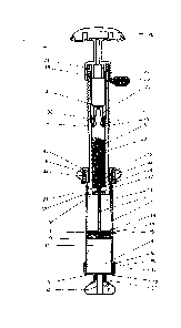
Figures 1 to 6 are depictions of a first bone cement applicator according to
the invention for the
storage of starting components 3, 4 of a bone cement 48 and for the mixing of
the bone cement 48.
In this context, Figures 1 and 4 to 6 show the work-flow of a method according
to the invention that
is implemented using the first bone cement applicator according to the
invention in the form of four
cross-sectional views of the first bone cement applicator according to the
invention.
The first bone cement applicator according to the invention comprises a tube-
shaped cartridge 1
made of plastics that forms a front part (on the bottom in Figures 1 to 6) of
the bone cement
applicator. A rear-side rear part of the bone cement applicator is formed by a
receptacle 2. The
bone cement applicator is intended for the production of a bone cement 48 (see
Figures 5 and 6)
that is produced from a monomer liquid 3 and from a bone cement powder 4. The
monomer liquid 3
and the bone cement powder 4 are the starting components 3, 4 of the bone
cement 48. The
monomer liquid 3 is contained in an ampoule 5 that can be fractured and is
made of glass or a
plastic material as the monomer liquid container for the monomer liquid 3,
whereby the ampoule 5
CA 3044592 2019-05-29
28
is plugged into the receptacle 2. The cartridge 1 forms a cylindrical internal
space 11 on its inside
that contains the bone cement powder 4. Accordingly, the bone cement
applicator is also well-
suited for storage of the monomer liquid 3 and bone cement powder 4.
The cartridge 1 comprises a cartridge lid 6 as cartridge head on its front
side (on the bottom in the
figures). A dispensing opening is provided in the cartridge lid 6. According
to an alternative variant
of the bone cement applicator, multiple gas supply openings (not shown)
through which a gas can
be aspirated from the inside of the bone cement applicator and through which a
sterilising gas such
as ethylene oxide can be filled in for sterilisation of the inside of the bone
cement applicator can be
situated in the side wall of the receptacle 2.
A mixing rod 7 is fastened to the front side of the receptacle 2 and extends
from the front side of the
receptacle 2 up into the front part of the cartridge 1, in which the bone
cement powder 4 is situated.
An internal thread 8 is situated on the rear-side end of the cartridge 1. The
receptacle 2 comprises,
on its outside, an external thread 9 with a diameter that is smaller than that
of the internal thread 8
of the cartridge 1. The receptacle 2 is shaped, in a rear region, in the way
of a threaded tube and
comprises, on its inside, a cylindrical chamber into which the ampoule 5 is
plugged. In a front area,
the receptacle 2 is cylinder-shaped on its outside, whereby four projecting
strips 47 are provided on
the external surface of the receptacle 2 parallel to the cylinder axis of the
receptacle 2. The
ampoule 5 has a cylindrical ampoule body with a diameter that matches the
inside of the receptacle
2. On the inside of the cartridge 1, the cartridge 1 forms the cylindrical
internal space 11. The
cylinder geometry of the internal space 11 and of the chamber of the
receptacle 2 corresponds to
cylinders with a circular footprint.
A mixer 10 is fastened to the front side of the mixing rod 7 in the form of
mixing vanes with a
surrounding scraping ring. The presence of a scraping ring allows the areas
right at the internal wall
of the internal space 11 to be reached.
The receptacle 2 is bordered on its front side by a wall with multiple
passages 36 as closure of the
front side, whereby the wall on the front side of the receptacle 2 closes the
chamber toward the
front at its circular base surface. A dispensing plunger 12 is arranged in the
internal space 11 of the
cartridge 1 such as to be mobile in axial direction of the cylindrical
internal space 11, and is
arranged in the internal space 11 in a press-fit. The mixing rod 7 is guided
through a central
passage in the dispensing plunger 12 such that the mixing rod 7 can be moved
against the
CA 3044592 2019-05-29
29
dispensing plunger 12 without the dispensing plunger 12 moving in the internal
space of the
cartridge 1 in this context. With the receptacle 2 retracted, the mixer 10
touches against the front
side of the dispensing plunger 12. As a result, the mixer 10 can reach the
entire front part of the
internal space 11 that is bordered on the side by the cartridge 1, on the
front by the cartridge lid 6,
and in the rear by the dispensing plunger 12. As a result, complete mixing of
the bone cement
powder 4 with the monomer liquid 3 in this area is ensured.
The dispensing plunger 12 comprises multiple channels 14 passing through the
dispensing plunger
12, which are arranged in a ring shape about the central passage for the
mixing rod 7 in the
dispensing plunger 12 and connect the front side of the dispensing plunger 12
to the rear side of
the dispensing plunger 12 and thereby connect the two sides of the internal
space 11 of the
cartridge 1 to each other. The channels 14 are covered by a ring-shaped pore
filter 16. The pore
filter 16 is impermeable to the bone cement powder 4 from the internal space
11 of the cartridge 1,
and is permeable to the monomer liquid 3 and gases. As a result, the bone
cement powder 4 is
prevented from ingress into the inside of the receptacle 2.
The dispensing plunger 12 comprises a larger external diameter than the
external thread 9 of the
receptacle 2. The external diameter of the cylindrical dispensing plunger 12
fits the internal
diameter of the internal space 11 of the cartridge 1. The dispensing plunger
12 seals the internal
space 11 of the cartridge 1.
An opening facility 18 is provided on the rear side of the receptacle 2 and
can be used to push the
ampoule 5 in the direction of the dispensing plunger 12 in order to open the
ampoule 5 on the
inside of the receptacle 2 such that the monomer liquid 3 in the receptacle 2
flows out. For this
purpose, the opening facility 18 comprises a two-step sleeve 20, whereby the
front side of the
sleeve 20 forms a hollow cylinder, in which an ampoule head of the ampoule 5
is arranged. The
sleeve 20 of the opening facility 18 can thus push onto shoulders 21 of the
ampoule 5 in order to
push same to the front in the direction of the dispensing plunger 12 and to
thus open it. Since the
sleeve 20 presses onto the shoulders 21, the force is guided through the
ampoule body to an
ampoule base 27 of the ampoule 5. The walls of the ampoule body are very
stable such that the
ampoule 5 will not fracture in this area. The ampoule 5 can thus be fractured
at the ampoule base
27.
CA 3044592 2019-05-29
30
In this context, the sleeve 20 touches against the internal wall of the
receptacle 2 and covers it in
the area of the rear side of the inside of the receptacle 2. The rear-side end
of the receptacle 2 is
covered by a closure cap 22 of the opening facility 18. A wall perpendicular
to the axis of the
cylinder geometry of the sleeve 20 is provided in the sleeve 20, whereby an
opening 23 is provided
in the wall. The opening 23 prevents a gas spring from being formed during the
insertion of the
receptacle 2 into the cartridge 1. Moreover, the monomer liquid 3 can flow
more easily out of the
receptacle 2, if air can flow through the opening 23. For application, the
bone cement applicator
needs to be held or set up with the cartridge lid 6 facing downwards, as is
shown in Figures 1 to 6.
The sleeve 20 is fastened to the screw-type closure cap 22. The closure cap 22
comprises an
internal thread 24 that fits the external thread 9 of the receptacle 2.
The closure cap 22, or the opening facility 18 as it may be, is screwed a way,
but not all the way to
a limit stop, onto the rear side of the receptacle 2 and is thus fastened to
same. It is important that
the closure cap 22 can be screwed further onto the receptacle 2 and that the
sleeve 20 can be
inserted more deeply into the receptacle 2 by this means to allow the ampoule
5 to be opened in
the receptacle 2.
On the rear side of the receptacle 2, a circumferential groove is provided in
the thread 9, into which
a securing element 26 in the form of a brace is plugged. The securing element
26 prevents the
closure cap 22 from being screwed onto the receptacle 2 inadvertently and thus
prevents the
opening facility 18 from being operated inadvertently. The securing element 26
can be detached
right before a use of the bone cement applicator by pulling off the securing
element 26. The
opening facility 18 can then be screwed into the receptacle 2.
In order to prevent the closure cap 22 from rotating in the wrong direction
and thus to prevent the
receptacle 2 from being opened on its rear side, a reverse motion lock is
provided (not shown in
Figures 1 to 6). The reverse motion lock prevents the closure cap 22 from
detaching and/or the
opening facility 18 from detaching from the receptacle 2. The reverse motion
lock can be
implemented, for example, as a screw lock in the form of a locking disk or by
a pair of wedge lock
disks or similar measures.
In order to be able to conveniently rotate the opening facility 18 and the
receptacle 2 by hand and in
order to be able to conveniently insert and pull out the receptacle 2 into and
out of the cartridge 1,
the rear-side end thereof is fitted with a handle 28. For sealing the sleeve
20 with respect to the
CA 3044592 2019-05-29
31
internal wall of the receptacle 2, two circumferential seals 30 made of rubber
are arranged in
circumferential grooves on the front-most external circumference of the sleeve
20. The sleeve 20 is
graduated on the outside and thus forms a limit stop in addition to the limit
stop formed by the
closure cap 22, whereby the limit stops prevent the opening facility 18 from
being screwed further
onto and/or into the receptacle 2.
Likewise, the external circumference of the dispensing plunger 12 has two
grooves arranged on it,
in which two circumferential seals 32 made of rubber are situated and which
are situated at a
distance from each other in longitudinal direction. The seals 32 seal the
dispensing plunger 12 with
respect to the internal space 11 of the cartridge 1 and separate the internal
space 11 of the
cartridge 1 into a front part, in which the bone cement powder 4 is arranged,
and a rear part.
A mandrel 34 for fracturing the ampoule 5 is arranged on the front wall of the
receptacle 2 that
points to the cartridge lid 6. For this purpose, the mandrel 34 points into
the inside of the receptacle
2. In order to open the ampoule 5, the ampoule 5 can be pushed, by the sleeve
20, onto the
mandrel 34 until the ampoule base 27 of the ampoule 5 is being pushed into the
ampoule body.
The mandrel 34 has a blunt tip whose purpose is to have the force act on the
ampoule 5 on a
middle area of the ampoule base 27 such that a predetermined breakage site in
the connection
between the ampoule base 27 and the side walls of the ampoule body is
utilised. The force for this
purpose is exerted via the sleeve 20. The sleeve 20 has approximately the same
diameter as the
ampoule body of the ampoule 5. The ampoule head of the ampoule 5 is arranged
on the inside of
the sleeve 20 in this context. What this attains is that the ampoule 5 is not
fractured in the area of
the sleeve 20, since the cylindrical ampoule body is very stable, whereas the
mandrel 34 can be
pushed relatively easily from the front into the ampoule 5.
The mixing rod 7 is fastened to the receptacle 2 inside the mandrel 34. The
mandrel 34 is
connected to the receptacle 2 by means of a predetermined breakage site such
that a pressure
being exerted on the mixing rod 7 causes the mixing rod 7 to sever the mandrel
34 from the
receptacle 2 such that the mixing rod 7 with the mandrel 34 at the tip can be
moved through the
front base surface of the receptacle 2. Alternatively, an internal circular
disk (not shown) of the front
side of the receptacle 2 can be connected to the receptacle 2 by means of a
thread such that the
mandrel 34 can be separated, by means of said circular disk, from the
remaining receptacle 2 by a
rotation of the receptacle 2 against the mixing rod 7, which is affixed to the
cartridge lid 6 for this
purpose, such that the mixing rod 7 again can be moved with respect to the
remaining receptacle 2.
CA 3044592 2019-05-29
32
Multiple passages 36 are arranged about the mandrel 34 and connect the inside
of the receptacle 1
to the internal space 11 of the cartridge 1. The monomer liquid 3 can flow
through the passages 36
into the internal space 11 of the cartridge 1, as is shown in Figure 4.
The front side of the cartridge 1 is closed by the cartridge lid 6. A socket
37 bordering the
dispensing opening in the cartridge lid 6 is formed in the middle of the
cartridge lid 6. A closure 38
for closing the dispensing opening is screwed into the socket 37 and is thus
fastened in detachable
manner. The closure 38 can be operated via wings 39 in the way of a wing
screw. The cartridge lid
6 is screwed onto an external thread 42 on the front side of the cartridge 1
by an internal thread 40.
The cartridge lid 6 is additionally sealed with respect to the cartridge 1 by
means of a
circumferential seal 43.
The front part of the internal space 11 of the cartridge 1 has the mixer 10
arranged in it, by means
of which the content of the front part of the internal space 11 can be mixed
through a manual
motion of the mixer 10. The manual motion of the mixer 10 takes place by
inserting and pulling out
the receptacle 2 into and from the cartridge 1. Namely, this also causes the
mixing rod 7, which is
fastened to the front side of the receptacle 2, to be moved back and forth in
linear manner. In this
context, the mixing rod 7 moves through the feedthrough in the dispensing
plunger 12, and the
mixer 10 fastened to the mixing rod 7 moves in the front part of the internal
space 11 of the
cartridge 1.
The internal thread 8 on the rear side of the cartridge 1 has a larger
diameter than the internal
space 11. A screw ring 44 with an external thread 45 that matches the internal
thread 8 is screwed
into the internal thread 8. The screw ring 44 has an internal thread 46 on its
inside that matches the
external thread 9 of the receptacle 2. Accordingly, the receptacle 2 can be
screwed into the internal
thread 46 of the screw ring 44 (see Figure 6).
In addition, the internal thread 46 of the screw ring 44 serves as a limit
stop for the insertion of the
receptacle 2 into the cartridge 1. Namely, when the receptacle 2 is being
inserted into the cartridge
1 up to the limit stop, the external thread 9 of the receptacle 2 meets the
internal thread 46 of the
screw ring 44, which is fully screwed into the internal thread 8 on the rear
side of the cartridge 1.
Concurrently, the length of the mixing rod 7 is selected appropriately such
that the mixer 10
touches against the cartridge lid 6 at the front side of the internal space
11. By this means, the
CA 3044592 2019-05-29
33
bone cement 48 at the front side of the internal space 11 can also be reached
and mixed by the
mixer 10.
The closure 38 projects a little ways into the internal space 11 of the
cartridge 1. A recess
accommodating the part of the closure 38 that projects into the internal space
11 is provided on the
front side of the mixer 10 that faces the cartridge lid 6. By this means, the
bone cement 48 touching
against the closure 38 and against the cartridge lid 6 can also be mixed, and
having this recess
also provides a free cross-section of flow to the bone cement 48, when the
closure 38 is removed
and the mixer 10 touches against the cartridge lid 6 during the dispensation
of the bone cement 48
(see Figure 6).
The work-flow of a method according to the invention is illustrated in the
following based on Figures
1 to 6. Initially, the bone cement applicator is in the starting state (see
Figures 1 to 3). In this state,
the bone cement applicator has been packaged and sterilised with ethylene
oxide. The ethylene
oxide can enter into the inside of the receptacle 2 through gaps in the
opening facility 18 and
through the opening 23 and can enter into the internal space 11 of the
cartridge 1 through the
passages 36, the pore filter 16, and the channels 14. The gas exchange takes
place in a vacuum
chamber or negative pressure chamber in this context. In this state (see
Figures 1 to 3), the bone
cement applicator is being unpacked.
The securing element 26 is pulled off first. The bone cement applicator is
being held with the
cartridge lid 6 downwards. Subsequently, the opening facility 18 is being
screwed into the
receptacle 2. As before, the bone cement applicator is being held with the
cartridge lid 6
downwards. In this context, the sleeve 20 pushes the shoulders 21 of the
ampoule 5 in downward
direction. Subsequently, the ampoule 5 is being pushed onto the mandrel 34 by
its ampoule base
27, and the ampoule 5 fractures at its ampoule base 27. This state is shown in
Figure 4.
The monomer liquid 3 exits from the opened ampoule 5 in the area of the
passages 36. Since the
bone cement applicator is being held with the cartridge lid 6 downwards, the
monomer liquid 3
driven by gravity immediately flows downwards through the passages 36, the
pore filter 16, and the
channels 14 into the internal space 11 of the cartridge 1 and distributes in
the bone cement powder
4 (see Figure 4). In order to accelerate the monomer transfer, the receptacle
2 can be pushed into
and pulled out of the cartridge 1.
CA 3044592 2019-05-29
=
34
The mixing of the bone cement 48 and/or of the starting components 3, 4 of the
bone cement 48
takes place by inserting and pulling out the receptacle 2 into and out of the
cartridge 1, while the
mixer 10 moves simultaneously in the internal space 11 of the cartridge 1. In
this context, the mixer
reaches all spaces in the internal space 11 between the dispensing plunger 12
and the cartridge
5 lid 6. To guide this motion, strips 47 touching against the internal
thread 46 of the screw ring 44 are
arranged on the outside of the receptacle 2 in the front area with no external
thread 9. The strips 47
prevent the receptacle 2 from wobbling during the mixing process. The gaps
allow air to escape
that would otherwise be enclosed between the screw ring 44, the external wall
of the receptacle 2,
the internal wall of the cartridge 1, and the seal 32. This prevents having to
work against the force
10 of a gas spring in this area while the bone cement 48 and/or the
starting components 3, 4 are being
mixed.
Finally, the bone cement 48 is successfully mixed and the receptacle 2 is
being inserted fully into
the cartridge 1 such that the mixer 10 touches against the cartridge lid 6.
This scenario is shown in
Figure 5.
In order to be able to screw the receptacle 2 into the internal thread 46 of
the screw ring 44, the
screw ring 44 needs to be unscrewed some way out of the internal thread 8 of
the cartridge 1 after
the bone cement 48 has been mixed. As a result, the internal thread 46 of the
screw ring 44 can
engage the external thread 9 of the receptacle 2. The screw ring 44 must not
be detached
completely from the cartridge 1 in this context. A suitable connecting means
(not shown) can be
provided for this purpose. By this means, the receptacle 2 can be screwed into
the screw ring 44
and thus into the cartridge 1. As a result, the receptacle 2 can be pushed
forcefully into the
cartridge 1. The front of the mixer 10 touches against the cartridge lid 6
such that the mixing rod 7
cannot get out of the way. The pressure transmitted by the mixing rod 7
detaches the mandrel 34
from the front wall of the receptacle 2 or the mixing rod 7 punctures the
mandrel 34. Concurrently,
the dispensing plunger 12, which is supported in a press fit, is detached from
the receptacle 2 and
driven in the direction of the cartridge lid 6.
When the receptacle 2 is being screwed further into the cartridge 1, the bone
cement 48 is expelled
out of the internal space 11 of the cartridge 1 through the opened dispensing
opening. For this
purpose, the closure 38 is first unscrewed from the dispensing opening and a
dispensing tube 49 is
screwed into the internal thread of the socket 37. For this purpose, the
dispensing tube 49 has an
external thread that matches the internal thread of the socket 37. The bone
cement 48 is pressed
CA 3044592 2019-05-29
35
between the mixer 10 and the cartridge lid 6, through the dispensing opening
and the socket 37 into
the dispensing tube 49. Subsequently, the bone cement 48 flows out of the
dispensing tube 49 and
is ready for application (see Figure 6).
During the extrusion of the bone cement 48, gas inclusions in the bone cement
48 are pushed
upwards into the receptacle 2 through the pore filter 16 such that a gas-
depleted bone cement 48 is
produced.
As an alternative to the dispensing tube 49, a hose with a trocar (not shown)
can be fastened to the
socket 37 through which the bone cement 48 can be applied under X-ray control
in places that are
difficult to access.
Figures 7 to 12 show depictions of a second alternative bone cement applicator
according to the
invention for storage of starting components 3, 4 of a bone cement 48 and for
mixing of the bone
cement 48. In this context, the figures also show the work-flow of a method
according to the
invention that is implemented using the second bone cement applicator
according to the invention
in the form of five cross-sectional views of the second bone cement applicator
according to the
invention.
The design of the second bone cement applicator according to the invention is
largely similar to that
of the first bone cement applicator according to the invention according to
Figures 1 to 6. The
second bone cement applicator according to the invention comprises a tube-
shaped cartridge 51
made of plastics that forms a front part (on the bottom in Figures 7 to 12) of
the bone cement
applicator. A rear-side rear part of the bone cement applicator is formed by a
receptacle 52. The
bone cement applicator is intended for the production of a bone cement 48 (see
Figures 11 and 12)
that is produced from a monomer liquid 3 and from a bone cement powder 4.
Accordingly, the
starting components 3, 4 are the same as used in the first exemplary
embodiment according to
Figures 1 to 6. Likewise, the monomer liquid 3 is contained in an identical
ampoule 5 that can be
fractured and is made of glass or a plastic material as the monomer liquid
container for the
monomer liquid 3, whereby the ampoule 5 is plugged into the receptacle 52. The
cartridge 51 forms
a cylindrical internal space 61 on its inside that contains the bone cement
powder 4. Accordingly,
the bone cement applicator is also well-suited for storage of the monomer
liquid 3 and bone cement
powder 4.
CA 3044592 2019-05-29
36
The cartridge 51 comprises a cartridge lid 56 as cartridge head on its front
side (on the bottom in
the figures). A dispensing opening is provided in the cartridge lid 56. A
mixing rod 57 is fastened to
the front side of the receptacle 52 and extends from the front side of the
receptacle 52 up into the
front part of the cartridge 51, in which the bone cement powder 4 is situated.
The receptacle 52 comprises an external thread 59 on its outside. The
receptacle 52 is shaped, in a
rear region, in the way of a threaded tube and comprises, on its inside, a
cylindrical chamber into
which the ampoule 5 is plugged. In a front area, the receptacle 52 is cylinder-
shaped on its outside,
whereby four projecting strips 97 are provided on the external surface of the
receptacle 52 parallel
to the cylinder axis of the receptacle 52. The ampoule 5 has a cylindrical
ampoule body with a
diameter that matches the inside of the receptacle 2. On the inside of the
cartridge 51, the cartridge
51 forms the cylindrical internal space 61. The cylinder geometry of the
internal space 61 and of the
chamber of the receptacle 52 corresponds to cylinders with a circular
footprint.
A mixer 60 is fastened to the front side of the mixing rod 57 in the form of
mixing vanes with a
surrounding scraping ring. The presence of a scraping ring allows the areas
right at the internal wall
of the internal space 61 to be reached.
The receptacle 52 is bordered on its front side by a wall with multiple
passages 86 as closure of the
front side, whereby the wall on the front side of the receptacle 52 closes the
chamber toward the
front at its circular base surface. A dispensing plunger 62 is arranged in the
internal space 61 of the
cartridge 51 such as to be mobile in axial direction of the cylindrical
internal space 61, and is
arranged in the internal space 61 in a press-fit. The mixing rod 57 is guided
through a central
passage in the dispensing plunger 62 such that the mixing rod 57 can be moved
against the
dispensing plunger 62 without the dispensing plunger 62 moving in the internal
space of the
cartridge 51 in this context. With the receptacle 52 retracted, the mixer 60
touches against the front
side of the dispensing plunger 62. As a result, the mixer 60 can reach the
entire front part of the
internal space 61 that is bordered on the side by the cartridge 51, on the
front by the cartridge lid
56, and in the rear by the dispensing plunger 62. As a result, complete mixing
of the bone cement
powder 4 with the monomer liquid 3 in this area is ensured.
The dispensing plunger 62 comprises multiple channels 64 passing through the
dispensing plunger
62, which are arranged in a ring-shape about the central passage for the
mixing rod 57 in the
dispensing plunger 62 and connect the front side of the dispensing plunger 62
to the rear side of
CA 3044592 2019-05-29
37
the dispensing plunger 62 and thereby connect the two sides of the internal
space 61 of the
cartridge 51 to each other. The channels 64 are covered by a ring-shaped pore
filter 66. The pore
filter 66 is impermeable to the bone cement powder 4 from the internal space
61 of the cartridge 51,
and is permeable to the monomer liquid 3 and gases. As a result, the bone
cement powder 4 is
prevented from ingress into the inside of the receptacle 52.
The dispensing plunger 62 comprises a larger external diameter than the
external thread 59 of the
receptacle 52. The external diameter of the cylindrical dispensing plunger 62
fits the internal
diameter of the internal space 61 of the cartridge 51. The dispensing plunger
62 seals the internal
space 61 of the cartridge 51.
An opening facility 68 is provided on the rear side of the receptacle 52 and
can be used to push the
ampoule 5 in the direction of the dispensing plunger 62 in order to open the
ampoule 5 on the
inside of the receptacle 52 such that the monomer liquid 3 in the receptacle
52 flows out. For this
purpose, the opening facility 68 comprises a two-step sleeve 70, whereby the
front side of the
sleeve 70 forms a hollow cylinder, in which an ampoule head of the ampoule 5
is arranged. The
sleeve 70 of the opening facility 68 can thus push onto shoulders 21 of the
ampoule 5 in order to
push same to the front in the direction of the dispensing plunger 62 and to
thus open it. Since the
sleeve 70 presses onto the shoulders 21, the force is guided through the
ampoule body to an
ampoule base 27 of the ampoule 5. The walls of the ampoule body are very
stable such that the
ampoule 5 will not fracture in this area. The ampoule 5 can thus be fractured
at the ampoule base
27.
In this context, the sleeve 70 touches against the internal wall of the
receptacle 52 and covers it in
the area of the rear side of the inside of the receptacle 52. The rear-side
end of the receptacle 52 is
covered by a closure cap 72 of the opening facility 68. A wall perpendicular
to the axis of the
cylinder geometry of the sleeve 70 is provided in the sleeve 70, whereby an
opening 73 is provided
in the wall. The opening 73 prevents a gas spring from being formed during the
insertion of the
receptacle 52 into the cartridge 51. Moreover, the monomer liquid 3 can flow
more easily out of the
receptacle 52, if air can flow through the opening 73. For application, the
bone cement applicator
needs to be held or set up with the cartridge lid 56 facing downwards, as is
shown in Figures 7 to
12. The sleeve 70 is fastened to the screw-type closure cap 72. The closure
cap 72 comprises an
internal thread 74 that fits the external thread 59 of the receptacle 52.
CA 3044592 2019-05-29
38
The closure cap 72, or the opening facility 68 as it may be, is screwed a way,
but not all the way to
a limit stop, onto the rear side of the receptacle 52 and is thus fastened to
same. It is important that
the closure cap 72 can be screwed further onto the receptacle 52 and that the
sleeve 70 can be
inserted more deeply into the receptacle 52 by this means to allow the ampoule
5 to be opened in
the receptacle 52.
On the rear side of the receptacle 52, a circumferential groove is provided in
the thread 59, into
which a securing element 76 in the form of a brace is plugged. The securing
element 76 prevents
the closure cap 72 from being screwed onto the receptacle 52 inadvertently and
thus prevents the
opening facility 68 from being operated inadvertently. The securing element 76
can be detached
right before a use of the bone cement applicator by pulling off the securing
element 76. The
opening facility 68 can then be screwed into the receptacle 52.
In order to prevent the closure cap 72 from rotating in the wrong direction
and thus to prevent the
receptacle 52 from being opened on its rear side, a reverse motion lock is
provided (not shown in
Figures 7 to 12). The reverse motion lock prevents the closure cap 72 from
detaching and/or the
opening facility 68 from detaching from the receptacle 52. The reverse motion
lock can be
implemented, for example, as a screw lock in the form of a locking disk or by
a pair of wedge lock
disks or similar measures.
In order to be able to conveniently rotate the opening facility 68 and the
receptacle 52 by hand and
in order to be able to conveniently insert and pull out the receptacle 52 into
and out of the cartridge
51, the rear-side end thereof is fitted with a handle 78. For sealing the
sleeve 70 with respect to the
internal wall of the receptacle 52, two circumferential seals 80 made of
rubber are arranged in
circumferential grooves on the front-most external circumference of the sleeve
70. The sleeve 70 is
graduated on the outside and thus forms a limit stop in addition to the limit
stop formed by the
closure cap 72, whereby the limit stops prevent the opening facility 68 from
being screwed further
onto and/or into the receptacle 52.
Likewise, the external circumference of the dispensing plunger 62 has two
grooves arranged on it,
in which two circumferential seals 82 made of rubber are situated and which
are situated at a
distance from each other in longitudinal direction. The seals 82 seal the
dispensing plunger 62 with
respect to the internal space 61 of the cartridge 51 and separate the internal
space 61 of the
cartridge 51 into a front part, in which the bone cement powder 4 is arranged,
and a rear part.
CA 3044592 2019-05-29
39
A mandrel 84 for fracturing the ampoule 5 is arranged on the front wall of the
receptacle 52 that
points to the cartridge lid 56. For this purpose, the mandrel 84 points into
the inside of the
receptacle 2. In order to open the ampoule 5, the ampoule 5 can be pushed, by
the sleeve 70, onto
the mandrel 84 until the ampoule base 27 of the ampoule 5 is being pushed into
the ampoule body.
The mandrel 84 has a blunt tip whose purpose is to have the force act on the
ampoule 5 on a
middle area of the ampoule base 27 such that a predetermined breakage site in
the connection
between the ampoule base 27 and the side walls of the ampoule body is
utilised. The force for this
purpose is exerted via the sleeve 70. The sleeve 70 has approximately the same
diameter as the
ampoule body of the ampoule 5. The ampoule head of the ampoule 5 is arranged
on the inside of
.. the sleeve 70 in this context. What this attains is that the ampoule 5 is
not fractured in the area of
the sleeve 70, since the cylindrical ampoule body is very stable, whereas the
mandrel 84 can be
pushed relatively easily from the front into the ampoule 5.
The mixing rod 57 is fastened to the receptacle 52 inside the mandrel 84. The
mandrel 84 is
connected to the receptacle 52 by means of a predetermined breakage site such
that a pressure
.. being exerted on the mixing rod 57 causes the mixing rod 57 to sever the
mandrel 84 from the
receptacle 52 such that the mixing rod 57 with the mandrel 84 at the tip can
be moved through the
front base surface of the receptacle 52. Alternatively, an internal circular
disk (not shown) of the
front side of the receptacle 52 can be connected to the receptacle 52 by means
of a thread such
that the mandrel 84 can be separated, by means of said circular disk, from the
remaining
receptacle 52 by a rotation of the receptacle 52 against the mixing rod 57,
which is affixed to the
cartridge lid 56 for this purpose, such that the mixing rod 57 again can be
moved with respect to the
remaining receptacle 52.
Multiple passages 86 are arranged about the mandrel 84 and connect the inside
of the receptacle
51 to the internal space 61 of the cartridge 51. The monomer liquid 3 can flow
through the
passages 86 into the internal space 61 of the cartridge 51, as is shown in
Figure 10.
The front side of the cartridge 51 is closed by the cartridge lid 56. A socket
87 bordering the
dispensing opening in the cartridge lid 56 is formed in the middle of the
cartridge lid 56. A closure
88 for closing the dispensing opening is screwed into the socket 87 and is
thus fastened in
detachable manner. The closure 88 can be operated via wings 89 in the way of a
wing screw. The
cartridge lid 56 is screwed onto an external thread 92 on the front side of
the cartridge 51 by an
CA 3044592 2019-05-29
40
internal thread 90. The cartridge lid 56 is additionally sealed with respect
to the cartridge 51 by
means of a circumferential seal 93.
The front part of the internal space 61 of the cartridge 51 has the mixer 60
arranged in it, by means
of which the content of the front part of the internal space 61 can be mixed
through a manual
motion of the mixer 60. The manual motion of the mixer 60 takes place by
inserting and pulling out
the receptacle 52 into and from the cartridge 51. Namely, this also causes the
mixing rod 57, which
is fastened to the front side of the receptacle 52, to be moved back and forth
in linear manner. In
this context, the mixing rod 57 moves through the feedthrough in the
dispensing plunger 62, and
the mixer 60 fastened to the mixing rod 57 moves in the front part of the
internal space 61 of the
cartridge 51.
A two-part sliding ring 94 is fastened to the rear side of the cartridge 51. A
limit stop 95 on the rear
side of the cartridge 51 prevents the sliding ring 94 from being separable
from the cartridge 51. The
two parts of the sliding ring 94 are being connected firmly to each other in
order to be able to
assemble the sliding ring 94 onto the limit stop 95. The external wall of the
cartridge 51 has
grooves 58, which engage the projections of the sliding ring 94, provided in
the area of the sliding
ring 94, such that the sliding ring 94 is linearly mobile only along the
grooves 58. The sliding ring 94
has an internal thread 96 on its inside that matches the external thread 59 of
the receptacle 52.
Accordingly, the receptacle 52 can be screwed into the internal thread 96 of
the sliding ring 94 (see
Figure 12).
In addition, the internal thread 96 of the sliding ring 94 serves as a limit
stop for the insertion of the
receptacle 52 into the cartridge 51. Namely, when the receptacle 52 is being
inserted into the
cartridge 51 up to the limit stop, the external thread 59 of the receptacle 52
meets the internal
thread 96 of the sliding ring 94, which is being pushed fully in the direction
of the cartridge lid 56.
Concurrently, the length of the mixing rod 57 is selected appropriately such
that the mixer 60
touches against the cartridge lid 56 at the front side of the internal space
61. By this means, the
bone cement 48 at the front side of the internal space 61 can also be reached
and mixed by the
mixer 60.
The closure 88 projects a little ways into the internal space 61 of the
cartridge 51. A recess
accommodating the part of the closure 88 that projects into the internal space
61 is provided on the
front side of the mixer 60 that faces the cartridge lid 56. By this means, the
bone cement 48
CA 3044592 2019-05-29
41
touching against the closure 88 and against the cartridge lid 56 can also be
mixed, and having this
recess also provides a free cross-section of flow to the bone cement 48, when
the closure 88 is
removed and the mixer 60 touches against the cartridge lid 56 during the
dispensation of the bone
cement 48 (see Figure 12).
The work-flow of a method according to the invention is illustrated in the
following based on Figures
7 to 12. Initially, the bone cement applicator is in the starting state (see
Figures 7 and 8). In this
state, the bone cement applicator has been packaged and sterilised with
ethylene oxide. The
ethylene oxide can enter into the inside of the receptacle 52 through gaps in
the opening facility 68
and through the opening 73 and can enter into the internal space 61 of the
cartridge 51 through the
passages 86, the pore filter 66, and the channels 64. The gas exchange takes
place in a vacuum
chamber or negative pressure chamber in this context. In this state (see
Figures 7 and 8), the bone
cement applicator is being unpacked.
The securing element 76 is pulled off first. The bone cement applicator is
being held with the
cartridge lid 56 downwards. Subsequently, the opening facility 68 is being
screwed into the
receptacle 52. As before, the bone cement applicator is being held with the
cartridge lid 56
downwards. In this context, the sleeve 70 pushes the shoulders 21 of the
ampoule 5 in downward
direction. Subsequently, the ampoule 5 is being pushed onto the mandrel 84 by
its ampoule base
27, and the ampoule 5 fractures at its ampoule base 27. Said scenario is shown
in Figures 9 and
10.
The monomer liquid 3 exits from the opened ampoule 5 in the area of the
passages 86. Since the
bone cement applicator is being held with the cartridge lid 56 downwards, the
monomer liquid 3
driven by gravity immediately flows downwards through the passages 86, the
pore filter 66, and the
channels 64 into the internal space 61 of the cartridge 51 and distributes in
the bone cement
powder 4 (see Figure 10). In order to accelerate the monomer transfer, the
receptacle 52 can be
pushed into and pulled out of the cartridge 51.
The mixing of the bone cement 48 and/or of the starting components 3, 4 of the
bone cement 48
takes place by inserting and pulling out the receptacle 52 into and out of the
cartridge 51, while the
mixer 60 moves simultaneously in the internal space 61 of the cartridge 51. In
this context, the
mixer 60 reaches all spaces in the internal space 61 between the dispensing
plunger 62 and the
cartridge lid 56. To guide this motion, strips 97 touching against the
internal thread 96 of the sliding
CA 3044592 2019-05-29
42
ring 94 are arranged on the outside of the receptacle 52 in the front area
with no external thread 59.
The strips 97 prevent the receptacle 52 from wobbling during the mixing
process. The gaps allow
air to escape that would otherwise be enclosed between the sliding ring 94,
the external wall of the
receptacle 52, the internal wall of the cartridge 51, and the seal 82. This
prevents having to work
against the force of a gas spring in this area while the bone cement 48 and/or
the starting
components 3, 4 are being mixed.
Finally, the bone cement 48 is successfully mixed and the receptacle 52 is
being inserted fully into
the cartridge 51 such that the mixer 60 touches against the cartridge lid 56.
This scenario is shown
in Figure 11.
In order to be able to screw the receptacle 52 into the internal thread 96 of
the sliding ring 94, the
sliding ring 94 is being pulled out of the cartridge 1 up to the limit stop 95
after the bone cement 48
has been mixed. As a result, the internal thread 96 of the sliding ring 94 can
engage the external
thread 59 of the receptacle 52. The sliding ring 94 cannot be detached
completely from the
cartridge 51 because of the limit stop 95. By this means, the receptacle 52
can be screwed into the
sliding ring 94 and thus into the cartridge 51. As a result, the receptacle 52
can be pushed forcefully
into the cartridge 51. The front of the mixer 60 touches against the cartridge
lid 56 such that the
mixing rod 57 cannot get out of the way. The pressure transmitted by the
mixing rod 57 detaches
the mandrel 84 from the front wall of the receptacle 52 or the mixing rod 57
punctures the mandrel
84. Concurrently, the dispensing plunger 62, which is supported in a press
fit, is detached from the
receptacle 52 and driven in the direction of the cartridge lid 56.
When the receptacle 52 is being screwed further into the cartridge 51, the
bone cement 48 is
expelled out of the internal space 61 of the cartridge 51 through the opened
dispensing opening.
For this purpose, the closure 88 is first unscrewed from the dispensing
opening and a dispensing
tube 49 is screwed into the internal thread of the socket 87. For this
purpose, the dispensing tube
49 has an external thread that matches the internal thread of the socket 87.
The bone cement 48 is
pressed between the mixer 60 and the cartridge 56, through the dispensing
opening and the socket
87 into the dispensing tube 49. Subsequently, the bone cement 48 flows out of
the dispensing tube
49 and is ready for application (see Figure 12).
CA 3044592 2019-05-29
=
43
During the extrusion of the bone cement 48, gas inclusions in the bone cement
48 are pushed
upwards into the receptacle 52 through the pore filter 66 such that a gas-
depleted bone cement 48
is produced.
As an alternative to the dispensing tube 49, a hose with a trocar (not shown)
can be fastened to the
socket 87 through which the bone cement 48 can be applied under X-ray control
in places that are
difficult to access.
The features of the invention disclosed in the preceding description and in
the claims, figures, and
exemplary embodiments, can be essential for the implementation of the various
embodiments of
the invention both alone and in any combination.
CA 3044592 2019-05-29
44
List of reference numbers
1, 51 Cartridge
2, 52 Receptacle / ampoule holder
3 Monomer liquid
4 Bone cement powder
5 Ampoule
6, 56 Cartridge lid / cartridge head
7, 57 Mixing rod
8 Internal thread
9, 59 External thread
10, 60 Mixer / mixing vane
11,61 Internal space
12, 62 Dispensing plunger
14, 64 Channel
16,66 Pore filter
18, 68 Opening facility
20, 70 Sleeve
21 Shoulder
22, 72 Closure cap
23, 73 Opening
24, 74 Internal thread
26, 76 Securing element
27 Ampoule base
28, 78 Handle
30, 80 Seal
32, 82 Seal
34, 84 Mandrel
36, 86 Passage
37, 87 Socket
38, 88 Closure
39, 89 Wing
40, 90 Internal thread
42, 92 External thread
CA 3044592 2019-05-29
45
43, 93 Seal
44 Screw ring
45 External thread
46, 96 Internal thread
47 Strip
48 Bone cement
49 Dispensing tube
58 Groove
94 Sliding ring
95 Limit stop
CA 3044592 2019-05-29