Note: Descriptions are shown in the official language in which they were submitted.
CA 03044834 2019-05-23
WO 2018/098239 PCT/US2017/062961
1
SINGLE INSERTION MULTIPLE SAMPLE BIOPSY APPARATUS
Cross-Reference To Related Applications
[0001] This application claims priority to U.S. provisional patent application
serial no.
62/425,974 filed November 23, 2016, which is incorporated herein by reference.
Technical Field
[0002] The present invention relates to biopsy devices, and, more
particularly, to a
single insertion multiple sample biopsy apparatus.
Background Art
[0003] A biopsy may be performed on a patient to help in determining whether
the
tissue in a region of interest includes cancerous cells. One biopsy technique
used to
evaluate breast tissue, for example, involves inserting a biopsy probe into
the breast tissue
region of interest to capture one or more tissue samples from the region. Such
a biopsy
technique often utilizes a vacuum to pull the tissue to be sampled into a
sample notch of
the biopsy probe, after which the tissue is severed and collected. Efforts
continue in the
art to improve the ability of the biopsy device to sever a tissue sample, and
to transport the
severed tissue sample to a sample collection container.
[0004] What is needed in the art is a biopsy device that has the ability to
promote
effective severing of a tissue sample and effective transport of the tissue
sample to a
sample collection container.
Summary of Invention
[0005] The present invention provides a biopsy device that has the ability to
promote
effective severing of a tissue sample and effective transport of the tissue
sample to a
sample collection container.
[0006] The invention in one form is directed to a biopsy apparatus that
includes a driver
assembly and a biopsy probe assembly. The driver assembly has an
electromechanical
power source and a vacuum source. The biopsy probe assembly is releasably
attached to
CA 03044834 2019-05-23
WO 2018/098239 PCT/US2017/062961
2
the driver assembly. The biopsy probe assembly has a vacuum cannula and a
stylet
cannula coaxially arranged along a longitudinal axis, with the vacuum cannula
being
positioned inside the stylet cannula. The vacuum cannula is coupled in fluid
communication with the vacuum source. The vacuum cannula has an elongate
portion and
a flared portion that extends distally from the elongate portion. The stylet
cannula is
coupled in driving communication with the electromechanical power source. The
stylet
cannula is movable relative to the vacuum cannula between a first extended
position and a
first retracted position. The stylet cannula has a proximal portion and a
distal portion.
The distal portion has a sample notch and a protrusion member that extends
proximally in
a lumen of the stylet cannula along a portion of a longitudinal extent of the
sample notch,
wherein when the stylet cannula is in the first retracted position, the
protrusion member is
received within the flared portion of the vacuum cannula.
[0007] The biopsy apparatus may further include a controller circuit that has
a virtual
energy reservoir, and the controller circuit executes program instructions to
control current
to motors when engaging dense tissue.
[0008] The invention in another form is directed to a biopsy apparatus that
includes a
driver assembly and a biopsy probe assembly. The driver assembly has an
electromechanical power source, a vacuum source, and a controller circuit. The
controller
circuit is electrically and communicatively coupled to the electromechanical
power source
and to the vacuum source. The biopsy probe assembly is releasably attached to
the driver
assembly. The biopsy probe assembly has a vacuum cannula, a stylet cannula,
and a cutter
cannula coaxially arranged along a longitudinal axis. The vacuum cannula is
positioned
inside the stylet cannula, and the stylet cannula is positioned inside the
cutter cannula.
The vacuum cannula is coupled in fluid communication with the vacuum source.
The
CA 03044834 2019-05-23
WO 2018/098239 PCT/US2017/062961
3
vacuum cannula has an elongate portion and a flared portion that extends
distally from the
elongate portion. The stylet cannula is coupled in driving communication with
the
electromechanical power source. The stylet cannula is movable relative to the
vacuum
cannula between a first extended position and a first retracted position. The
stylet cannula
has a proximal portion and a distal portion. The distal portion has a sample
notch and a
protrusion member that extends proximally in a lumen of the stylet cannula
along a
portion of a longitudinal extent of the sample notch. When the stylet cannula
is in the
retracted position, the protrusion member of the stylet cannula is received
within the flared
portion of the vacuum cannula. The cutter cannula is coupled in driving
communication
with the electromechanical power source. The cutter cannula is movable
relative to the
stylet cannula between a second extended position to cover the sample notch
and a second
retracted position to expose the sample notch when the stylet cannula is in
the first
extended position.
Brief Description of Drawings
[0009] The above-mentioned and other features and advantages of this
invention, and
the manner of attaining them, will become more apparent and the invention will
be better
understood by reference to the following description of an embodiment of the
invention
taken in conjunction with the accompanying drawings, wherein:
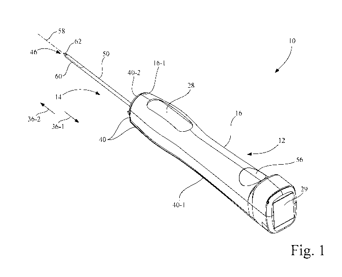
[0010] Fig. 1 is a perspective view of a biopsy apparatus configured in
accordance with
an embodiment of the present invention, with a biopsy probe assembly attached
to a driver
assembly;
[0011] Fig. 2 is a perspective view of the biopsy apparatus of Fig. 1, with
the biopsy
probe assembly detached from the driver assembly and with the driver assembly
inverted
to expose the drive features of the driver assembly;
[0012] Fig. 3 is a block representation of the driver assembly of Fig. 1;
CA 03044834 2019-05-23
WO 2018/098239 PCT/US2017/062961
4
[0013] Fig. 4 is an exploded view of the biopsy probe assembly of Fig. 1;
[0014] Fig. 5A is a section view of the biopsy probe assembly of Fig. 1, taken
along line
5A-5A of Fig. 2;
[0015] Fig. 5B is an enlarged portion of the vacuum cannula depicted in Fig.
5A;
[0016] Fig. 5C is an enlarged portion of the stylet cannula depicted in Fig.
5A;
[0017] Fig. 6A shows the relative positions of the vacuum cannula, the stylet
cannula,
and the cutter cannula before, during, and immediately after a piercing shot;
[0018] Fig. 6B shows the relative positions of the vacuum cannula, the stylet
cannula,
and the cutter cannula, and with the cutter cannula retracted to expose the
sample notch of
the stylet cannula;
[0019] Fig. 6C shows the relative positions of the vacuum cannula, the stylet
cannula,
and the cutter cannula, depicting a shaking of the sample notch by
alternatingly moving
the stylet cannula in the proximal direction and in the distal direction for a
short distance;
[0020] Fig. 6D shows the relative positions of the vacuum cannula, the stylet
cannula,
and the cutter cannula, wherein the cutter cannula is rotated and translated
in the distal
direction to sever a tissue sample from the tissue received in the sample
notch;
[0021] Fig. 6E shows the relative positions of the vacuum cannula, the stylet
cannula,
and the cutter cannula, wherein the stylet cannula is moved within the cutter
cannula in the
proximal direction to mechanically aid in moving the tissue sample into the
flared portion
of the vacuum cannula;
[0022] Fig. 6F shows the relative positions of the vacuum cannula, the stylet
cannula,
and the cutter cannula, wherein the stylet cannula is moved within the cutter
cannula in the
distal direction to disengage the protrusion member from the flared portion of
the vacuum
cannula;
CA 03044834 2019-05-23
WO 2018/098239 PCT/US2017/062961
[0023] Fig. 6G shows the relative positions of the vacuum cannula, the stylet
cannula,
and the cutter cannula, wherein the stylet cannula is again moved within the
cutter cannula
in the proximal direction, such that the protrusion member re-engages the
flared portion of
the vacuum cannula;
[0024] Fig. 6H shows the relative positions of the vacuum cannula, the stylet
cannula,
and the cutter cannula, wherein the stylet cannula is again moved within the
cutter cannula
in the distal direction to disengage the protrusion member from the flared
portion of
vacuum cannula and return to the extended position;
[0025] Fig. 7 is a vacuum/time graph depicting a baseline vacuum pressure at
several
different positions during a tissue sample cutting and transport sequence as
depicted in
Figs. 6A-6H;
[0026] Fig. 8A is a graph of actual motor winding current (I) of a motor of
the driver
assembly of Fig. 1, to be viewed in conjunction with the graph of Fig. 8B; and
[0027] Fig. 8B is a graph of the energy status of a virtual energy reservoir
established in
a memory circuit of the driver assembly of Fig. 1, to be viewed in conjunction
with the
graph of Fig. 8A.
[0028] Corresponding reference characters indicate corresponding parts
throughout the
several views. The exemplifications set out herein illustrate at least one
embodiment of
the invention, and such exemplifications are not to be construed as limiting
the scope of
the invention in any manner.
Description of Embodiments
[0029] Referring now to the drawings, and more particularly to Figs. 1 and 2,
there is
shown a biopsy apparatus 10 which generally includes a non-invasive, e.g., non-
disposable, driver assembly 12 and an invasive, e.g., disposable, biopsy probe
assembly
14. As used herein, the term "non-disposable" is used to refer to a device
that is intended
CA 03044834 2019-05-23
WO 2018/098239 PCT/US2017/062961
6
for use on multiple patients during the lifetime of the device, and the term
"disposable" is
used to refer to a device that is intended to be disposed of after use on a
single patient.
Driver assembly 12 includes a driver housing 16 that is configured and
ergonomically
designed to be grasped by a user.
[0030] Referring to Figs. 2 and 3, driver assembly 12 includes within driver
housing 16
a controller circuit 18, an electromechanical power source 20, a vacuum source
22, a
vacuum sensor 24, and a battery 26 (or alternatively an AC adapter). A user
interface 28
(see Fig. 1), such as a keypad, is located to be mounted to driver housing 16,
and
externally accessible by the user with respect to driver housing 16. Battery
26 may be, for
example, a rechargeable battery, which may be charged by an inductive charging
device
coupled to inductive coil 29, or alternatively, by an electrical connection to
an electrical
power supply. Battery 26 is electrically coupled to controller circuit 18,
electromechanical
power source 20, vacuum source 22, and user interface 28.
[0031] Referring to Fig. 3, user interface 28 may include control buttons and
visual/aural
indicators, with the control buttons providing user control over various
functions of biopsy
apparatus 10, and with the visual/aural indicators providing visual/aural
feedback of the
status of one or more conditions and/or positions of components of biopsy
apparatus 10.
The control buttons may include a sample button 28-1 and a prime/pierce button
28-2.
The visual indicators may include a display screen 28-3 and/or one or more
light emitting
diodes (LED) 28-4. The aural indicator may include a buzzer 28-5. The control
buttons
may include tactile feedback to the user when activated.
[0032] Controller circuit 18 is electrically and communicatively coupled to
electromechanical power source 20, vacuum source 22, vacuum sensor 24, and
user
interface 28, such as by one or more wires or circuit traces. Controller
circuit 18 may be
CA 03044834 2019-05-23
WO 2018/098239
PCT/US2017/062961
7
assembled on an electrical circuit board, and includes, for example, a
processor circuit 18-
1 and a memory circuit 18-2.
[0033] Processor circuit 18-1 has one or more programmable microprocessors and
associated circuitry, such as an input/output interface, clock, buffers,
memory, etc.
Memory circuit 18-2 is communicatively coupled to processor circuit 18-1,
e.g., via a bus
circuit, and is a non-transitory electronic memory that may include volatile
memory
circuits, such as random access memory (RAM), and non-volatile memory
circuits, such
as read only memory (ROM), electronically erasable programmable ROM (EEPROM),
NOR flash memory, NAND flash memory, etc. Controller circuit 18 may be formed
as
one or more Application Specific Integrated Circuits (ASIC).
[0034] Controller circuit 18 is configured via software and/or firmware
residing in
memory circuit 18-2 to execute program instructions to perform functions
associated with
the retrieval of biopsy tissue samples, such as that of controlling and/or
monitoring one or
more components of electromechanical power source 20, vacuum source 22, and
vacuum
sensor 24.
[0035] Electromechanical power source 20 may include, for example, a cutter
module
30, a transport module 32, and a piercing module 34, each being respectively
electrically
coupled to battery 26. Each of cutter module 30, transport module 32, and
piercing
module 34 is electrically and controllably coupled to controller circuit 18 by
one or more
electrical conductors, e.g., wires or circuit traces.
[0036] Cutter module 30 may include an electrical motor 30-1 having a shaft to
which a
drive gear 30-2 is attached. Transport module 32 may include an electrical
motor 32-1
having a shaft to which a drive gear 32-2 is attached. Piercing module 34 may
include an
electrical motor 34-1, a drive spindle 34-2, and a piercing shot drive 34-3.
Each electrical
CA 03044834 2019-05-23
WO 2018/098239 PCT/US2017/062961
8
motor 30-1, 32-1, 34-1 may be, for example, a direct current (DC) motor or
stepper motor.
As an alternative to the arrangement described above, each of cutter module
30, transport
module 32, and piercing module 34 may include one or more of a gear, gear
train,
belt/pulley arrangement, etc., interposed between the respective motor and
drive gear or
drive spindle.
[0037] Piercing module 34 is configured such that an activation of electrical
motor 34-1
and a drive spindle 34-2 causes a piercing shot drive 34-3 to move in a
proximal direction
36-1 to compress a firing spring, e.g., one or more coil springs, and to latch
piercing shot
drive 34-3 in a ready position. Upon actuation of prime/pierce button 28-2 of
user
interface 28, piercing shot drive 34-3 is propelled, i.e., fired, in a distal
direction 36-2 (see
Fig. 2).
[0038] Vacuum source 22 is electrically and controllably coupled to battery 26
by one or
more electrical conductors, e.g., wires or circuit traces. Vacuum source 22
may include,
for example, an electric motor 22-1 that drives a vacuum pump 22-2. Vacuum
source 22
has a vacuum source port 22-3 coupled to vacuum pump 22-2 for establishing
vacuum in
biopsy probe assembly 14. Electric motor 22-1 may be, for example, a rotary,
linear or
vibratory DC motor. Vacuum pump 22-2 may be, for example, a peristaltic pump
or a
diaphragm pump, or one or more of each connected in series or parallel.
[0039] Vacuum sensor 24 is electrically coupled to controller circuit 18 by
one or more
electrical conductors, e.g., wires or circuit traces. Vacuum sensor 24 may be
a pressure
differential sensor that provides vacuum (negative pressure) feedback signals
to controller
circuit 18. In some implementations, vacuum sensor 24 may be incorporated into
vacuum
source 22.
CA 03044834 2019-05-23
WO 2018/098239 PCT/US2017/062961
9
[0040] Referring to Figs. 1 and 2, biopsy probe assembly 14 is configured for
releasable
attachment to driver assembly 12. As used herein, the term "releasable
attachment" means
a configuration that facilitates an intended temporary connection followed by
selective
detachment involving a manipulation of disposable biopsy probe assembly 14
relative to
driver assembly 12, without the need for tools.
[0041] Referring to the exploded view of Fig. 4, biopsy probe assembly 14
includes a
probe housing 40, a probe sub-housing 42, a vacuum cannula 44, a stylet
cannula 46, a
stylet gear-spindle set 48 for linear stylet translation, a cutter cannula 50,
a cutter gear-
spindle set 52 for rotary and linear cutter translation, a sample manifold 54,
and a sample
cup 56.
[0042] Referring to Figs. 2, 4, and 5A, probe housing 40 is formed as an L-
shaped
structure having an elongate portion 40-1 and a front plate 40-2. When biopsy
probe
assembly 14 is attached to driver assembly 12, front plate 40-2 is positioned
distally
adjacent to an entirety of front surface 16-1 of driver housing 16, i.e., so
as to shield the
entirety of front surface 16-1 of the non-disposable driver assembly from
contact with a
patient.
[0043] Vacuum cannula 44, stylet cannula 46, and cutter cannula 50 are
coaxially
arranged along a longitudinal axis 58 in a nested tube arrangement, with
vacuum cannula
44 being the innermost tube, cutter cannula 50 being the outermost tube, and
stylet
cannula 46 being the intermediate tube that is interposed between vacuum
cannula 44 and
cutter cannula 50. In other words, vacuum cannula 44 is positioned inside
stylet cannula
46, and stylet cannula 46 is positioned inside cutter cannula 50.
CA 03044834 2019-05-23
WO 2018/098239 PCT/US2017/062961
[0044] Vacuum cannula 44 is mounted to be stationary relative to probe sub-
housing 42.
Vacuum cannula 44 is coupled in fluid communication with vacuum source 22 via
sample
manifold 54.
[0045] Referring to Figs. 4, 5A, and 5B, vacuum cannula 44 includes an
elongate
portion 44-1 and a flared portion 44-2 that extends distally from elongate
portion 44-1.
Elongate portion 44-1 has a first outside diameter Dl. Flared portion 44-2
flares from
elongate portion 44-1 in two stages, namely, a first flared stage 45-1 and a
second flared
stage 45-2. First flared stage 45-1 diverges from elongate portion 44-1 at a
first acute
angle Al, and second flared stage 45-2 diverges from first flared stage 45-1
at a second
acute angle A2 relative to elongate portion 44-1, with acute angle A2 being
larger than
acute angle Al. A distal outside diameter D2 of second flared stage 45-2 is
selected to be
accommodated within, and in sliding contact with, lumen 46-4 of stylet cannula
46. Each
of first flared stage 45-1 and second flared stage 45-2 of flared portion 44-2
has a distally
and gradually increasing diameter, which is larger than the diameter D1 of
elongate
portion 44-1.
[0046] Referring again to Fig. 4, stylet cannula 46 includes a proximal
portion 46-1 and
a distal portion 46-2. Distal portion 46-2 includes a sample notch 60.
Attached to distal
portion 46-2 is a piercing tip 62, which in turn forms part of stylet cannula
46. Stylet gear-
spindle set 48 threadably engages a transport spindle 42-3 is fixedly attached
(e.g., glued,
welded or staked) to proximal portion 46-1 of stylet cannula 46. Stylet gear-
spindle set 48
is a unitary gear having a driven gear 48-1 fixedly attached to a threaded
spindle 48-2, and
may be formed as a single molded component. Stylet cannula 46 is retracted or
extended
along longitudinal axis 58 by activation of transport module 32 of biopsy
probe assembly
CA 03044834 2019-05-23
WO 2018/098239 PCT/US2017/062961
11
14, with drive gear 32-2 of transport module 32 of driver assembly 12 being
engaged with
driven gear 48-1 of stylet gear-spindle set 48.
[0047] Referring also to Fig. 5C, 6A, and 6B, sample notch 60 is formed as an
elongate
opening in a side wall 46-3 of stylet cannula 46 to facilitate a reception of
tissue 66 into a
lumen 46-4 of stylet cannula 46. Sample notch 60 has a longitudinal extent 60-
1 that
extends along longitudinal axis longitudinal axis 58. Sample notch 60 does not
extend in
side wall 46-3 below a centerline of the diameter of stylet cannula 46, and
may include
cutting edges around the perimeter of the opening formed by sample notch 60,
wherein the
cutting edges of the elongate (linear) portions of sample notch 60 each have a
cutting edge
46-5 that diverges from a cutting edge along the side wall 46-3 to the
centerline at a
diameter of stylet cannula 46.
[0048] Piercing tip 62 has a tip portion 62-1, a mounting portion 62-2, and a
protrusion
member 62-3. Piercing tip 62 is inserted into lumen 46-4 of stylet cannula 46
at distal
portion 46-2, with mounting portion 62-2 being attached to distal portion 46-2
of stylet
cannula 46, such as an adhesive or weld. As such, tip portion 62-1 extends
distally from
distal portion 46-2 of stylet cannula 46, and protrusion member 62-3 extends
proximally
(i.e., in proximal direction 36-1) in lumen 46-4 along a portion of the
longitudinal extent
60-1 of sample notch 60. Accordingly, as depicted in Figs. 6E and 6G, when
stylet
cannula 46 is fully retraced in the proximal direction 36-1, protrusion member
62-3 is
received into flared portion 44-2 of vacuum cannula 44. At least the proximal
tip portion
of protrusion member 62-3 has a proximally decreasing diameter.
[0049] Referring again to Fig. 4, cutter cannula 50 includes a proximal
portion 50-1 and
a distal portion 50-2. Distal portion 50-2 includes an annular cutting edge
64. Cutter
gear-spindle set 52 is fixedly attached (e.g., glued, welded or staked) to
proximal portion
CA 03044834 2019-05-23
WO 2018/098239 PCT/US2017/062961
12
50-1 of cutter cannula 50. Cutter gear-spindle set 52 is a unitary gear having
a driven gear
52-1 fixedly attached to a threaded spindle 52-2, and may be formed as a
single molded
component. Cutter cannula 50 is retracted or extended along longitudinal axis
58 by
activation of cutter module 30 of biopsy probe assembly 14, with drive gear 30-
2 of cutter
module 30 of driver assembly 12 being engaged with driven gear 52-1 of cutter
gear-
spindle set 52. Thus, cutter cannula 50 has a rotational cutting motion and is
translated
axially along longitudinal axis 58. The pitch of the threads of threaded
spindle 52-2
determines the number of revolutions per axial distance (in millimeters (mm))
that cutter
cannula 50 moves axially.
[0050] Referring to Figs. 4 and 5A, sample manifold 54 is configured as an L-
shaped
structure having a vacuum chamber portion 54-1 and a collection chamber
portion 54-2.
Vacuum chamber portion 54-1 includes a vacuum input port 54-3 that is arranged
to
sealably engage vacuum source port 22-3 of vacuum source 22 of driver assembly
12
when biopsy probe assembly 14 is attached to driver assembly 12. Vacuum
chamber
portion 54-1 is connected in fluid communication with collection chamber
portion 54-2.
Proximal end of elongate portion 44-1 of vacuum cannula 44 passes through
vacuum
chamber portion 54-1 and is in direct fluid communication with collection
chamber
portion 54-2. Collection chamber portion 54-2 has a cavity sized and arranged
to
removably receive sample cup 56, such that sample cup 56 is in direct fluid
communication with elongate portion 44-1 of vacuum cannula 44, and sample cup
56 also
is in direct fluid communication with vacuum input port 54-3 of vacuum chamber
portion
54-1. Blotting papers are placed in vacuum chamber portion 54-1 in a region
between
vacuum input port 54-3 and collection chamber portion 54-2.
CA 03044834 2019-05-23
WO 2018/098239 PCT/US2017/062961
13
[0051] Accordingly, a tissue sample severed by cutter cannula 50 at sample
notch 60 of
stylet cannula 46 may be transported by vacuum applied by vacuum source 22 at
sample
cup 56, through vacuum cannula 44, and into sample cup 56.
[0052] Referring again to Fig. 2, 4 and 5A, probe sub-housing 42 is a sub-
housing that is
slidably coupled to probe housing 40, e.g., using a rail/slot arrangement.
Probe sub-
housing 42 includes a proximal threaded portion 42-1 and a distal threaded
portion 42-2.
[0053] Proximal threaded portion 42-1 in probe sub-housing 42 has a threaded
hole that
threadably receives threaded spindle 48-2 of stylet gear-spindle set 48, such
that rotation
of driven gear 48-1 of stylet gear-spindle set 48 results in a linear
translation of stylet
cannula 46 along longitudinal axis 58, with a direction of rotation
correlating to a direction
of translation of stylet cannula 46 in one of proximal direction 36-1 and
distal direction
36-2. Driven gear 48-1 of stylet gear-spindle set 48 engages drive gear 32-2
of transport
module 32 when biopsy probe assembly 14 is attached to driver assembly 12 (see
Fig. 1).
[0054] Likewise, distal threaded portion 42-2 of probe sub-housing 42 has a
threaded
hole that threadably receives threaded spindle 52-2 of cutter gear-spindle set
52, such that
rotation of driven gear 52-1 of cutter gear-spindle set 52 results in a
combined rotation and
linear translation of cutter cannula 50 along longitudinal axis 58, with a
direction of
rotation correlating to a direction of translation of cutter cannula 50.
Driven gear 52-1 of
cutter gear-spindle set 52 engages drive gear 30-2 of cutter module 30 when
biopsy probe
assembly 14 is attached to driver assembly 12 (see Fig. 1).
[0055] Also, when biopsy probe assembly 14 is attached to driver assembly 12,
referring
also to Figs. 2 and 3, probe sub-housing 42 is connected to piercing shot
drive 34-3 of
piercing module 34. As such, upon a first actuation of prime/pierce button 28-
2, probe
sub-housing 42 and piercing shot drive 34-3 are translated in unison in
proximal direction
CA 03044834 2019-05-23
WO 2018/098239 PCT/US2017/062961
14
36-1 to position piercing shot drive 34-3 and probe sub-housing 42 carrying
stylet cannula
46 and cutter cannula 50 in the ready, i.e., cocked position, and upon a
second actuation of
prime/pierce button 28-2 to effect a piercing shot, probe sub-housing 42 and
piercing shot
drive 34-3 are rapidly propelled in unison in distal direction 36-2 to
position stylet cannula
46 and cutter cannula 50 at the distal most position of the combined elements,
e.g., within
the patient.
[0056] Figs. 6A-6H collectively represent a tissue sample severing and
transport
sequence. Figs. 6E and 6G show stylet cannula 46 in its retracted position 68-
1. Figs. 6A,
6B, and 6H show stylet cannula 46 in its extended position 68-2, sometimes
also referred
to as a zero position. Figs. 6C, 6D, and 6F show stylet cannula 46 in various
positions
intermediate to retracted position 68-1 and extended position 68-2. Figs. 6B
and 6C show
cutter cannula 50 in its retracted position 70-1, which exposes sample notch
60 of stylet
cannula 46 when stylet cannula 46 is in or near its extended position 68-2.
Figs. 6A and
6D-6H show cutter cannula 50 in its extended position 70-2, sometimes also
referred to as
a zero position, wherein cutter cannula 50 covers the sample notch 60 of
stylet cannula 46.
[0057] To effect the described movements of stylet cannula 46, controller
circuit 18
executes program instructions and sends respective control signals to
transport module 32
of driver assembly 12, which in turn transfers the motion to stylet gear-
spindle set 48 of
biopsy probe assembly 14. Likewise, to effect the described movements of
cutter cannula
50, controller circuit 18 executes program instructions and sends respective
control signals
to cutter module 30 of driver assembly 12, which in turn transfers the motion
to cutter
gear-spindle set 52 of biopsy probe assembly 14. Controller circuit 18 may
determine an
axial position of each of stylet cannula 46 and cutter cannula 50, relative to
the respective
CA 03044834 2019-05-23
WO 2018/098239 PCT/US2017/062961
zero position, by counting the respective number of motor drive pulses, or
alternatively,
the respective number of motor shaft revolutions.
[0058] Fig. 6A shows the relative positions of vacuum cannula 44, stylet
cannula 46,
and cutter cannula 50 before, during, and immediately after the piercing shot
effected by
piercing module 34. As shown, distal portion 50-2 of cutter cannula 50 is
extended over
sample notch 60.
[0059] In the sequence step illustrated in Fig. 6B, vacuum source 22 is
actuated to
deliver a vacuum via vacuum cannula 44 to lumen 46-4 of stylet cannula 46 at
sample
notch 60, and cutter cannula 50 is retracted by actuation of cutter module 30
to expose
sample notch 60, thereby permitting tissue 66 to be drawn into lumen 46-4 of
stylet
cannula 46 through sample notch 60. In the present embodiment, in order to
expose
sample notch 60, cutter cannula 50 rotates counterclockwise to effect a linear
translation
of cutter cannula 50 in proximal direction 36-1 for a distance of
approximately 23
millimeters (mm) to define the open length of sample notch 60. As used herein,
the
relative term "approximately" means the base value in the indicated units (if
any) plus or
minus five percent, unless stated otherwise. The actual aperture size at
sample notch 60,
corresponding to a desired sample size, may be user-selected at user interface
28, wherein
a distance that cutter cannula 50 is retracted toward retracted position 70-1
from extended
position 70-2 is controlled by controller circuit 18 to correspond to the
sample size
selected by the user.
[0060] Figs. 6C and 6D illustrate a cutting sequence.
[0061] In the sequence step illustrated in Fig. 6C, in order to increase the
size of tissue
sample to be collected, stylet cannula 46 may be moved alternatingly in
proximal direction
36-1 and distal direction 36-2 a short distance e.g., 2 to 5 mm, so as to
shake sample notch
CA 03044834 2019-05-23
WO 2018/098239 PCT/US2017/062961
16
60, thereby increasing the amount of tissue 66 that passes through sample
notch 60 and
into lumen 46-4 of stylet cannula 46. The last move of the shake is defined to
keep sample
notch 60 in a 1 mm retracted position (see Fig. 6C) compared to the zero
position of stylet
cannula 46 as depicted in Fig. 6A. This is to ensure that cutter cannula 50
closes sample
notch 60 during the cutting sequence (see Fig. 6D) and will cut 1 mm further,
to thus
ensure that connective tissue or strings are completely cut during the cutting
sequence step
illustrated in Fig 6D.
[0062] In the cutting sequence step illustrated in Fig. 6D, cutter cannula 50
is rotated
and translated in distal direction 36-2 to sever a tissue sample 66-1 from
tissue 66. In the
present embodiment, cutter cannula 50 rotates clockwise to effect a linear
translation of
cutter cannula in distal direction 36-2 for a distance of approximately 23 mm
in order to
cut the tissue and return to the zero position.
[0063] Figs. 6E-6H illustrate a tissue sample transport sequence.
[0064] In the sequence step illustrated in Fig. 6E, vacuum is applied by
vacuum cannula
44, and stylet cannula 46 is moved within cutter cannula 50 in proximal
direction 36-1 to
mechanically aid in moving tissue sample 66-1 into flared portion 44-2 of
vacuum cannula
44. More particularly, as stylet cannula 46 is moved within cutter cannula 50
in proximal
direction 36-1, protrusion member 62-3 of piercing tip 62 engages tissue
sample 66-1 to
assist tissue sample 66-1 into vacuum cannula 44. Protrusion member 62-3 then
engages
flared portion 44-2 of vacuum cannula 44 to close off an air inflow into
flared portion 44-2
of vacuum cannula 44.
[0065] In the sequence step illustrated in Fig. 6F, with vacuum being applied
by vacuum
cannula 44, stylet cannula 46 is moved within cutter cannula 50 in distal
direction 36-2 to
disengage protrusion member 62-3 from the flared portion 44-2 of vacuum
cannula 44 to
CA 03044834 2019-05-23
WO 2018/098239 PCT/US2017/062961
17
cause an abrupt change in air flow into vacuum cannula 44, thereby helping the
vacuum
transport of tissue sample 66-1 through vacuum cannula 44.
[0066] The sequence steps illustrated in Figs. 6G and 6H are essentially a
repeat of
sequence steps 6E and 6F.
[0067] In the sequence step illustrated in Fig. 6G, with vacuum applied to
vacuum
cannula 44 by vacuum source 22, stylet cannula 46 is again moved within cutter
cannula
50 in proximal direction 36-1, such that protrusion member 62-3 of piercing
tip 62 re-
engages flared portion 44-2 of vacuum cannula 44 to again close off an air
inflow into
flared portion 44-2 of vacuum cannula 44.
[0068] In the sequence step illustrated in Fig. 6H, with vacuum being applied
to vacuum
cannula 44 by vacuum source 22, stylet cannula 46 is moved within cutter
cannula 50 in
distal direction 36-2 to again disengage protrusion member 62-3 from flared
portion 44-2
of vacuum cannula 44 to cause an abrupt change in air flow into vacuum cannula
44,
thereby helping the vacuum transport of tissue sample 66-1 (if not already
delivered by
sequence steps of Figs. 6E and 6F) through vacuum cannula 44. At the end of
the
sequence of Fig. 6H, stylet cannula 46 is re-positioned at the tissue
receiving position i.e.,
extended position 68-2, also referred to as the zero position, and is ready to
receive tissue
for a next tissue sample, in which the sequence steps of Figs. 6A-6H would be
repeated.
[0069] It is noted that the sample transport sequence illustrated in Figs. 6E
and 6F may
be repeated as many times as necessary to complete the vacuum transport of
tissue sample
66-1 through vacuum cannula 44. Also, the backward motion of protrusion member
62-3
of piercing tip 62 of stylet cannula 46 in proximal direction 36-1 may be
implemented as
incremental steps, alternating between a backward motion and then a forward
motion (the
CA 03044834 2019-05-23
WO 2018/098239
PCT/US2017/062961
18
forward distance being less than the backward distance) until the final
position (retracted
position 68-1) is reached, as depicted in Figs. 6E and 6G.
[0070] Fig. 7 is a vacuum graph depicting a baseline vacuum pressure at
different
positions during the tissue sample cutting and transport sequence depicted in
Figs. 6A-6H.
[0071] Referring to the vacuum graph of Fig. 7, it is noted that vacuum is
applied
throughout the entire sequence depicted in Figs. 6A-6H. At time TO, vacuum
source 22 is
activated, and vacuum (negative pressure) builds in vacuum cannula 44. At time
Ti,
maximum vacuum is achieved, which corresponds to the end of the cutting
sequence step
depicted in Fig. 6D. At time T2, the tissue stuffing sequence of Figs. 6E-6F
begins, and
vacuum pressure abruptly drops due to a moment in which vent holes 80 in
stylet cannula
46 are not restricted. Vacuum begins to build prior to time T3 as protrusion
member 62-3
of piercing tip 62 approaches flared portion 44-2 of vacuum cannula 44, and
maximizes,
representing the end of the first stuffing sequence depicted in Fig. 6E. At
time T3,
vacuum pressure abruptly drops due to protrusion member 62-3 of piercing tip
62 being
moved away from flared portion 44-2 as depicted in Fig. 6F. In some instances,
tissue
sample 66-1 may have been delivered to sample cup 56. At time T4, the second
stuffing
sequence depicted in Figs. 6G and 6H begins. Time T5 corresponds to the end of
the
second stuffing sequence depicted in Fig. 6G. At time T6, vacuum pressure
drops due to
protrusion member 62-3 of piercing tip 62 again being moved away from flared
portion
44-2 as depicted in Fig. 6H, and back to the tissue receiving (zero) position.
[0072] By comparing an actual vacuum pressure to the baseline vacuum graph
depicted
in Fig. 7 at different stages of the tissue cutting and transport sequence
depicted in Figs.
6A-6H, cutting or tissue transport anomalies can be identified and corrective
action can be
attempted.
CA 03044834 2019-05-23
WO 2018/098239 PCT/US2017/062961
19
[0073] In accordance with an aspect of the invention, vacuum sensor 24
provides
vacuum pressure feedback signals to controller circuit 18, and controller
circuit 18
executes program instructions to determine whether the actual vacuum pressure
provided
by vacuum sensor 24 deviates by more than a predetermined amount from the
baseline
pressure of the vacuum graph of Fig. 7 at a corresponding point in the tissue
cutting and
transport sequence. The predetermined amount may be, for example, the baseline
vacuum
pressure plus or minus 10 percent. If the deviation is outside the acceptable
range of
deviation, then corrective action may be taken depending upon when in the
tissue cutting
and transport sequence the anomaly occurred.
[0074] For example, if the vacuum pressure falls below the baseline by more
than the
allowable deviation during the time period between times Ti and T2, this may
be an
indication of an incomplete cut, and thus controller circuit 18 may repeat the
cutting
sequence depicted in Figs. 6C and 6D without user intervention, rather than
immediately
going into an error state. Similarly, if the vacuum pressure rises above the
baseline by
more than the allowable deviation between the times T3 to T5, this may be an
indication
of an incomplete tissue transport through vacuum cannula 44, and thus
controller circuit
18 may increase the number of iterations of sequence steps 6E and 6F without
user
intervention.
[0075] Referring again to Fig. 5A, vacuum is maintained in biopsy probe
assembly 14
by a series of seals. A seal 72, e.g., a sleeve-type seal or 0-ring
arrangement, is located to
provide a seal between cutter cannula 50 and stylet cannula 46. A seal 74,
e.g., an 0-ring,
is located to provide a seal between stylet cannula 46 and vacuum cannula 44.
A seal 76,
e.g., a sleeve-type seal or 0-ring arrangement, is located to provide a seal
between vacuum
cannula 44 and vacuum chamber portion 54-1 of sample manifold 54. Also, a seal
78 may
CA 03044834 2019-05-23
WO 2018/098239 PCT/US2017/062961
be located in collection chamber portion 54-2 of sample manifold 54 and sample
cup 56.
Finally, a seal is placed at vacuum input port 54-3 at the vacuum interface
between biopsy
probe assembly 14 and driver assembly 12
[0076] During operation, vacuum pump 22-2 of vacuum source 22 will build up
vacuum
(negative pressure) in the vacuum reservoir formed by sample manifold 54 and
sample cup
56. More particularly, the volume of sample cup 56 and sample manifold 54 will
define
the strength of a "vacuum boost", and also defines the cycle time for vacuum
pump 22-2
of vacuum source 22. In the present embodiment, for example, the volume is
approximately 10 milliliters.
[0077] Regarding the "vacuum boost", stylet cannula 46 has one or more vent
openings
80, e.g., annularly arranged, at a predetermined distance proximal from tip
portion 62-1,
and these vent openings 80 (see Fig. 4) will be exposed to the atmosphere when
the stylet
cannula 46 is retracted to retracted position 68-1 (see Figs. 6E and 6G),
wherein vent
openings 80 slide under seal 72 between cutter cannula 50 and stylet cannula
46. Once
these vent openings 80 are exposed to the atmosphere, the system is 'open' and
the build-
up vacuum pressure will be equalized with the surrounding pressure so as to
create the
vacuum boost effect, in addition to the continuous flow delivered by vacuum
pump 22-2
of vacuum source 22.
[0078] Referring again to Fig. 3, when activating the cutter motor 30-1 for
cutting tissue
by moving cutter cannula 50 or activating transport motor 32-1 for
transporting tissue by
moving stylet cannula 46, each motor pulls current from battery 26. This
current will
linearly increase with load on the respective motor. Thus, the amount of
current
consumed can be translated into load. When working with dense tissue, the load
may
CA 03044834 2019-05-23
WO 2018/098239
PCT/US2017/062961
21
increase, and this is detected by monitoring the current using a current
monitoring
program executed by controller circuit 18.
[0079] Each of cutter motor 30-1 and transport motor 32-1 has a maximum
continuous
current rating (load) at which the motor can run indefinitely, and when the
respective
motor exceeds this continuous current (load), the motor can only run for a
limited time
before the motor is damaged (e.g., the windings burn in the motor), wherein
the higher the
load the shorter the time. The current monitoring program executed by
controller circuit
18 monitors the current for each motor, and when the current exceeds the
maximum
continuous level for a respective motor, then it is determined that the motor
has entered
dense tissue, and driver assembly will go into a dense tissue mode.
[0080] When dense tissue is encountered, controller circuit 18 controls the
current
supplied to the respective motor to provide motor protection and to permit the
motor
current to exceed the maximum continuous current rating for short periods of
time, based
on the status (virtual energy level) of a virtual energy reservoir that is
established in
memory circuit 18-2 of controller circuit 18.
[0081] The idea is to exert as much strength of the motor as possible without
damaging
the motor windings, when such challenging dense tissue is encountered. Once
the motor,
e.g., cutter motor 30-1 and/or transport motor 32-1, starts running in any of
the phases, the
motor speed (revolutions per minute (rpm)) is set as 100% based on the voltage
being set
in controller circuit 18, e.g., to e.g. 6 volts, and then an increase in load
(torque) will
increase the current consumption and potentially slow down the motor until it
stalls.
Controller circuit 18 has the option of increasing the voltage from 6 volts
to, e.g., 9 volts
and by that increase the speed (rpm) and stall torque, and thus overcome more
dense
tissue. In the present example, it is assumed that each motor has three
separate windings,
CA 03044834 2019-05-23
WO 2018/098239 PCT/US2017/062961
22
or phases. It was recognized, however, that some very dense tissue could
potentially stall
the motor from rotating, and meanwhile only one of the motor phases or
windings is in
conduction, which will lead a dramatic temperature increase in this single
phase and lead
to burn-out of the motor. The virtual energy reservoir is used for monitoring
the heat
when running between continues torque level and stall torque level, where
there is a risk to
burn the motor windings.
[0082] In accordance with an aspect of the invention, it is possible to exceed
the
continuous current level, e.g., when encountering dense tissue, and still
protect the motor
without sacrificing motor performance.
[0083] It is assumed that each of the motor is initialized at rest, and the
ambient
temperature is the normal room temperature. By keep tracking of the instant
current
consumption over the operation time, a corresponding increment of motor
winding
temperature can be predicted. Thus, for dense tissue detection/motor
protection, a virtual
energy reservoir is established in memory circuit 18-2 for each motor cutter
motor 30-1
and transport motor 32-1. The virtual energy reservoir can be filled up or
drained at
runtime based on integrating the difference of the actual motor winding
current and the
nominal motor winding current (maximum continuous current) over time. The
motor
winding temperature starts to increase when the actual motor winding current
is higher
than the nominal motor winding current (maximum continuous current), and vice
versa.
[0084] Controller circuit 18 thus executes program instructions to predict
when the
winding temperature is above its thermal limit, and if so determined,
controller circuit 18
will send control signals to the respective cutter module 30 or transport
module 32 to
lower the motor torque before the respective motor gets too hot. The algorithm
executed
as program instructions by controller circuit 18 is as follows:
CA 03044834 2019-05-23
WO 2018/098239 PCT/US2017/062961
23
f (12 - 1n2)t wherein: "I" represents the actual motor winding current;
"In" represents the nominal current of the motor windings; and
"t" represent time.
[0085] Fig. 8A is a graph of actual motor winding current (I), and Fig. 8B is
a graph of
the energy status of the virtual energy reservoir established in memory
circuit 18-2. In the
graph of Fig. 8B, STH represents the upper threshold and STL represents the
lower
threshold of the virtual energy reservoir.
[0086] Referring to Figs. 8A and 8B in combination, when the motor starts
running from
tO, there is a huge current spike for the motor to accelerate, at the same
time, the virtual
energy reservoir starts to be filled though it has not exceeded the upper
threshold. The
virtual energy reservoir is empty at ti, and the virtual energy reservoir
continues being
zero until the current abruptly increases again at t2. When the energy
accumulation in the
virtual energy reservoir is over the upper threshold STH for the first time at
t3, then
controller circuit 18 takes immediate action to reduce the current supplied to
the respective
motor to a safe level (predefined). The virtual energy reservoir level begins
to drop from
then on, even though the virtual energy reservoir level has been experienced
with a very
short overshooting. When the energy accumulation of the virtual energy
reservoir level
drops below the lower threshold STL at t4, then controller circuit 18 takes
immediate
action to increase, i.e., boost, the current again. The same process may be
repeated three
times before controller circuit 18 designates the condition as an error
condition, meaning
that the tissue is significantly dense, i.e., too dense to be cut. The three
repeated times
before error is predefined in the software executed by controller circuit 18.
The number of
repetitions may be varied, if desired, based at least in part on the length of
the cycle time
(e.g., the time of t5 ¨ t3).
CA 03044834 2019-05-23
WO 2018/098239 PCT/US2017/062961
24
[0087] In the present embodiment, the dense tissue mode is entered
automatically when
driver assembly 12 is powered on, and runs all the time after driver assembly
12 has been
powered.
[0088] The following items also relate to the invention:
[0089] In one form, the invention relates to a biopsy apparatus that includes
a driver
assembly and a biopsy probe. The driver assembly has an electromechanical
power source
and a vacuum source. The biopsy probe assembly is releasably attached to the
driver
assembly. The biopsy probe assembly has a vacuum cannula and a stylet cannula
coaxially arranged along a longitudinal axis. The vacuum cannula is positioned
inside the
stylet cannula. The vacuum cannula is coupled in fluid communication with the
vacuum
source. The vacuum cannula has an elongate portion and a flared portion that
extends
distally from the elongate portion. The stylet cannula is coupled in driving
communication with the electromechanical power source. The stylet cannula is
movable
relative to the vacuum cannula between a first extended position and a first
retracted
position. The stylet cannula has a proximal portion and a distal portion. The
distal portion
has a sample notch and a protrusion member that extends proximally in a lumen
of the
stylet cannula along a portion of a longitudinal extent of the sample notch.
When the
stylet cannula is in the first retracted position, the protrusion member is
received within
the flared portion of the vacuum cannula.
[0090] The flared portion of the vacuum cannula may have a first flared stage
that
diverges from the elongate portion at a first acute angle relative to the
elongate portion,
and a second flared stage that diverges from the first flared stage at a
second acute angle
relative to the elongate portion. Optionally, the second acute angle is larger
than the first
acute angle.
CA 03044834 2019-05-23
WO 2018/098239 PCT/US2017/062961
[0091] The biopsy probe assembly may further include a cutter cannula coaxial
with the
stylet cannula and the vacuum cannula, wherein the stylet cannula is
positioned within the
cutter cannula. The cutter cannula is movable relative to the stylet cannula
between a
second extended position to cover the sample notch and a second retracted
position to
expose the sample notch when the stylet cannula is in the first extended
position.
[0092] In any of the embodiments, the driver assembly optionally includes a
driver
housing that has a front surface. The biopsy probe assembly has a probe
housing with an
elongate portion, and in any of the embodiments, may include a front plate.
When the
biopsy probe assembly is attached to the driver assembly, the front plate is
positioned
distally adjacent to an entirety of the front surface of the driver housing so
as to shield the
entirety of the front surface of the driver assembly from contact with a
patient.
[0093] In any of the embodiments, the driver assembly may include a controller
circuit
and an electromechanical power source. The controller circuit is electrically
and
communicatively coupled to the electromechanical power source. The
electromechanical
power source has a cutter module and a transport module. The cutter module has
a first
motor and the transport module has a second motor. When the biopsy probe
assembly is
attached to the driver assembly, the cutter module is drivably coupled to the
cutter cannula
and the transport module is drivably coupled to the stylet cannula. Each of
the first motor
and the second motor has a maximum continuous current rating at which the
respective
motor can run indefinitely. The controller circuit is configured to execute
program
instructions to control the current for each of the first motor and the second
motor. The
controller circuit is configured to determine that the motor has entered dense
tissue, when
the current exceeds the maximum continuous level for a respective motor.
CA 03044834 2019-05-23
WO 2018/098239 PCT/US2017/062961
26
[0094] In any of the embodiments having a controller circuit, the controller
circuit may
include a processor circuit and memory circuit, and may have a virtual energy
reservoir
established in the memory circuit for each of the first motor and the second
motor. The
processor is configured to execute program instructions to control the current
supplied to a
respective motor to provide motor protection and to permit the respective
motor current to
exceed the maximum continuous current rating for short periods of time, based
on the
status of the virtual energy reservoir.
[0095] In any of the embodiments having at least one virtual energy reservoir,
each
virtual energy reservoir can be filled up or drained. The controller circuit
may be
configured to integrate a difference between an actual motor winding current
for a
respective motor and the maximum continuous current rating over time. The
controller
circuit may be configured to take action to reduce the current supplied to the
respective
motor, when an energy accumulation level in the virtual energy reservoir is
over an upper
threshold. The controller circuit may be configured to take action to increase
the current
supplied to the respective motor, when the energy accumulation level of the
virtual energy
reservoir level drops below a lower threshold. The apparatus may be controlled
such that
when an energy accumulation level in the virtual energy reservoir is over an
upper
threshold, the controller circuit then takes action to reduce the current
supplied to the
respective motor. The apparatus may be controlled such that when the energy
accumulation level of the virtual energy reservoir level drops below a lower
threshold, the
controller circuit then takes action to increase the current supplied to the
respective motor.
[0096] In any of the embodiments having a controller circuit, the controller
circuit may
be configured to execute program instructions to repeatedly move the
protrusion member
of the stylet cannula into and away from the flared portion of the vacuum
cannula to aid in
CA 03044834 2019-05-23
WO 2018/098239 PCT/US2017/062961
27
delivering a tissue sample into the flared portion of the vacuum cannula. The
apparatus
may be controlled such that vacuum may be continuously applied to the vacuum
cannula
during the time that the protrusion member of the stylet cannula is repeatedly
moved into
and away from the flared portion of the vacuum cannula.
[0097] In another form, the invention relates to a biopsy apparatus having a
driver
assembly that has an electromechanical power source, a vacuum source, and a
controller
circuit electrically and communicatively coupled to the electromechanical
power source
and to the vacuum source. A biopsy probe assembly is releasably attached to
the driver
assembly. The biopsy probe assembly has a vacuum cannula, a stylet cannula,
and a cutter
cannula coaxially arranged along a longitudinal axis. The vacuum cannula is
positioned
inside the stylet cannula. The stylet cannula is positioned inside the cutter
cannula. The
vacuum cannula is coupled in fluid communication with the vacuum source. The
vacuum
cannula has an elongate portion and a flared portion that extends distally
from the elongate
portion. The stylet cannula is coupled in driving communication with the
electromechanical power source. The stylet cannula is movable relative to the
vacuum
cannula between a first extended position and a first retracted position. The
stylet cannula
has a proximal portion and a distal portion. The distal portion has a sample
notch and a
protrusion member that extends proximally in a lumen of the stylet cannula
along a
portion of a longitudinal extent of the sample notch. When the stylet cannula
is in the
retracted position, the protrusion member is received within the flared
portion of the
vacuum cannula. The cutter cannula is coupled in driving communication with
the
electromechanical power source. The cutter cannula is movable relative to the
stylet
cannula between a second extended position to cover the sample notch and a
second
CA 03044834 2019-05-23
WO 2018/098239 PCT/US2017/062961
28
retracted position to expose the sample notch when the stylet cannula is in
the first
extended position.
[0098] The controller circuit may be configured to execute program
instructions to
control the apparatus such that the protrusion member of the stylet cannula is
repeatedly
moved into and away from the flared portion of the vacuum cannula to aid in
delivering a
tissue sample into the flared portion of the vacuum cannula. The apparatus may
be
controlled such that vacuum is continuously applied to the vacuum cannula
during the
time that the protrusion member of the stylet cannula is repeatedly moved into
and away
from the flared portion of the vacuum cannula.
[0099] The electromechanical power source may include a cutter module and a
transport
module. The cutter module has a first motor and the transport module has a
second motor.
When the biopsy probe assembly is attached to the driver assembly, the cutter
module is
drivably coupled to the cutter cannula and the transport module is drivably
coupled to the
stylet cannula.
[00100] Each of the first motor and the second motor has a maximum continuous
current rating at which the respective motor can run indefinitely. The
controller circuit is
configured to execute program instructions to control the current for each of
the first
motor and the second motor. The controller circuit may be configured to
determine that
the motor has entered dense tissue, when the current exceeds the maximum
continuous
level for a respective motor.
[00101] The controller circuit may include a processor circuit and memory
circuit. The
controller circuit may have a virtual energy reservoir established in the
memory circuit for
each of the first motor and the second motor. The processor may be configured
to execute
program instructions to control the current supplied to a respective motor to
provide motor
CA 03044834 2019-05-23
WO 2018/098239 PCT/US2017/062961
29
protection and to permit the respective motor current to exceed the maximum
continuous
current rating for short periods of time, based on the status of the virtual
energy reservoir.
[00102] In any of the embodiments having at least one virtual energy
reservoir, each
virtual energy reservoir can be filled up or drained. The controller circuit
is configured to
integrate a difference between an actual motor winding current for a
respective motor and
the maximum continuous current rating over time. The controller circuit may be
configured to reduce the current supplied to the respective motor, when an
energy
accumulation level in the virtual energy reservoir is over an upper threshold.
The
controller circuit may be configured to increase the current supplied to the
respective
motor, when the energy accumulation level of the virtual energy reservoir
level drops
below a lower threshold. The apparatus may be controlled such that when an
energy
accumulation level in the virtual energy reservoir is over an upper threshold,
the controller
circuit then takes action to reduce the current supplied to the respective
motor. The
apparatus may be controlled such that when the energy accumulation level of
the virtual
energy reservoir level drops below a lower threshold, the controller circuit
then takes
action to increase the current supplied to the respective motor.
[00103] The flared portion of the vacuum cannula may have a first flared stage
that
diverges from the elongate portion at a first acute angle relative to the
elongate portion,
and a second flared stage that diverges from the first flared stage at a
second acute angle
relative to the elongate portion. Optionally, the second acute angle is larger
than the first
acute angle.
[00104] While this invention has been described with respect to at least one
embodiment, the present invention can be further modified within the spirit
and scope of
this disclosure. This application is therefore intended to cover any
variations, uses, or
CA 03044834 2019-05-23
WO 2018/098239
PCT/US2017/062961
adaptations of the invention using its general principles. Further, this
application is
intended to cover such departures from the present disclosure as come within
known or
customary practice in the art to which this invention pertains and which fall
within the
limits of the appended claims.