Note: Descriptions are shown in the official language in which they were submitted.
AIRCRAFT LAVATORY DOOR LATCH
CROSS REFERENCE TO RELATED APPLICATIONS
FIELD OF THE INVENTION
[0002] The present
invention relates generally to an aircraft lavatory door latch.
BACKGROUND OF THE INVENTION
[0003] Commercial aircraft, such as the Airbus A320 or Boeing 737, are
typically
constructed from components, the size, weight and construction of which are
dictated by
many considerations, including fuselage dimensions, aesthetic and safety. Many
of these
requirements are imposed by law or regulation. Aircraft components, such as
overhead
stowage compartments, seats, lavatories, galleys, lighting systems, etc. are
all required to
function within strictly confined spaces.
[0004] Manufacturers of aircraft are constantly refining interior aircraft
designs to achieve more
comfort and utility for passengers and crew within carrier-imposed restraints
on cost,
weight, maintenance down-time, and safety. Commercial passenger aircraft
generally
include lavatories for use by passengers and crew that include a door on one
of the walls
thereof. Opening and closing and latching a bi-fold or blade door can often be
tricky.
Sometimes it is difficult for a passenger to tell whether the door is latched
properly or not.
The present invention helps make the latching opening of a bi-fold door more
intuitive and
obvious. This, together with other advantages of the door module, are
discussed below.
SUMMARY OF THE PREFERRED EMBODIMENTS
[0005] In accordance with a first aspect of the present invention there is
provided a door latch
assembly configured to be used in an aircraft lavatory door. The door latch
assembly
includes a housing that includes a housing interior, a switch member
operatively associated
with the housing that is rotatable between a first position and a second
position, and a
1
Date Recue/Date Received 2020-08-11
CA 03045919 2019-05-31
WO 2018/136957
PCT/US2018/014897
locking bolt that is movable linearly between an unlocked position and a
locked position.
Rotation of the switch member from the first position to the second position
moves the
locking bolt from the unlocked position to the locked position. In a preferred
embodiment.
the door latch assembly includes at least a first indicator member that is
rotatable with the
switch member between the first position and the second position. The first
indicator
member includes a locked portion and an unlocked portion. The housing includes
an
exterior indicator window. When the switch member is in the locked position
the locked
portion of the first indicator member is visible through the exterior
indicator window, and
when the switch member is in the unlocked position the unlocked portion of the
first
indicator member is visible through the exterior indicator window.
[0006] In a preferred embodiment, the housing also includes an interior
indicator window
and when the switch member is in the locked position the locked portion of the
indicator
member is visible through the interior indicator window. When the switch
member is in the
unlocked position the unlocked portion of the indicator member is visible
through the
interior indicator window. In a preferred embodiment, the door latch assembly
also
includes a rotating member that is rotatable with the switch member between
the first
position and the second position. The rotating member includes an unlocked
indicator
window and a locked indicator window. The unlocked indicator window is at
least partially
aligned with the interior indicator window and the exterior indicator window
when the
switch member is in the first position, and the locked indicator window is at
least partially
aligned with the interior indicator window and the exterior indicator window
when the
switch member is in the second position.
[0007] In a preferred embodiment, the door latch assembly includes a gear
train operatively
connected to the switch member and the gear train includes at least a first
gear (preferably
round) meshed with a rack gear. Preferably, the door latch assembly includes
an overcenter
2
assist spring having an end that is connected to and rotates with the first
gear. The assist
spring is configured to compress and then expand as the switch member rotates
from the
first position to the second position.
[0008] In a preferred embodiment, the door latch assembly includes an override
assembly that
includes a main body portion and a finger lid hingedly connected to the main
body portion.
The finger lid is pivotable between a stowed position and a deployed position.
Rotation of
the finger lid from a first position to a second position moves the locking
bolt from the
unlocked position to the locked position. Preferably, the finger lid is
secured in the stowed
position by a magnet. In a preferred embodiment, rotation of the finger lid
from the first
position to the second position rotates the switch member from the first
position to the
second position. Preferably, rotation of the switch member from the first
position to the
second position rotates the finger lid from the first position to the second
position.
[0009] In a preferred embodiment, the door latch assembly includes a
connecting rod that extends
from the switch member to the rotating member. The connecting rod extends
through the
second indicator member. Preferably, the locking bolt is movable vertically
between the
unlocked position and the locked position.
[0010] Described herein is a preferred embodiment of a door latch and lock. In
a preferred
embodiment, the door latch or switch system is used in an aircraft lavatory.
However, this
is not a limitation on the present invention, and the description herein of
the door latch
being used in an aircraft is only exemplary. In particular, in a preferred
embodiment, the
door latch is used with the lavatory door taught in U.S. Patent No. 9,428,259,
issued on
August 30, 2016. However, this is not a limitation on the present invention.
The door latch
can be used with a bi-fold or a blade door.
3
Date Recue/Date Received 2020-08-11
CA 03045919 2019-05-31
WO 2018/136957
PCT/US2018/014897
BRIEF DESCRIPTION OF THE DRAWINGS
[0011] The invention may be more readily understood by referring to the
accompanying
drawings in which:
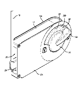
[0012] FIG. 1 is a perspective view of a door latch assembly in accordance
with a preferred
embodiment of the present invention;
[0013] FIG. 2A is a front elevational view of the door latch assembly of
FIG. 1 showing the
indicator portion between the first and second (locked and unlocked)
positions;
[0014] FIG. 2B is a rear elevational view of the door latch assembly of
FIG. 1 showing the
indicator portion between the first and second (locked and unlocked)
positions;
[0015] FIG. 3 is an exploded perspective view of the door latch assembly of
FIG. 1;
[0016] FIG. 4A is an elevational view of the interior of the housing of the
door latch
assembly of FIG. 1 showing the locking bolt in the unlocked position;
[0017] FIG. 4B is an elevational view of the interior of the housing of the
door latch
assembly of FIG. 1 showing the locking bolt in the locked position;
[0018] FIG. 5 is a perspective view of the door latch assembly of FIG. 1
showing the
override finger lid between the stowed and deployed positions;
[0019] FIG. 5A is a front elevational view of the door latch assembly of
FIG. 1 showing the
override finger lid in the deployed position and in the first (locked)
position;
[0020] FIG. 5B is a front elevational view of the door latch assembly of
FIG. 1 showing the
override finger lid in the deployed position and in the second (unlocked)
position;
[0021] FIG. 6 is a perspective view of the door latch assembly of FIG. 1
installed in a bi-
fold door with the front housing cover removed;
[0022] FIG. 7 is a perspective view of a bi-fold door with the door latch
assembly of FIG. I
installed therein;
4
CA 03045919 2019-05-31
WO 2018/136957
PCT/US2018/014897
[0023] FIG. 8A is an elevational view of the interior of the housing of
another door latch
assembly and showing the locking bolt in the unlocked position; and
[0024] FIG. 8B is an elevational view of the interior of the housing of the
door latch
assembly of FIG. 8A showing the locking bolt in the locked position.
[0025] Like numerals refer to like parts throughout the several views of
the drawings.
DETAILED DESCRIPTION OF THE PREFERRED EMBODIMENTS
[0026] The following description and drawings are illustrative and are not
to be construed as
limiting. Numerous specific details are described to provide a thorough
understanding of
the disclosure. However, in certain instances, well-known or conventional
details are not
described in order to avoid obscuring the description. References to one or an
embodiment
in the present disclosure can be, but not necessarily are references to the
same
embodiment; and, such references mean at least one of the embodiments.
[0027] Reference in this specification to "one embodiment" or "an
embodiment" means that
a particular feature, structure, or characteristic described in connection
with the
embodiment is included in at least one embodiment of the-disclosure. The
appearances of
the phrase "in one embodiment" in various places in the specification are not
necessarily
all referring to the same embodiment, nor are separate or alternative
embodiments
mutually exclusive of other embodiments. Moreover, various features are
described which
may be exhibited by some embodiments and not by others. Similarly, various
requirements
are described which may be requirements for some embodiments but not other
embodiments.
[0028] The terms used in this specification generally have their ordinary
meanings in the art,
within the context of the disclosure, and in the specific context where each
term is used.
Certain terms that are used to describe the disclosure are discussed below, or
elsewhere in
CA 03045919 2019-05-31
WO 2018/136957
PCT/US2018/014897
the specification, to provide additional guidance to the practitioner
regarding the
description of the disclosure. For convenience, certain terms may be
highlighted, for
example using italics and/or quotation marks: The use of highlighting has no
influence on
the scope and meaning of a term: the scope and meaning of a term is the same,
in the same
context, whether or not it is highlighted.
[0029] It will be appreciated that the same thing can be said in more than
one way.
Consequently, alternative language and synonyms may be used for any one or
more of the
terms discussed herein. No special significance is to be placed upon whether
or not a term
is elaborated or discussed herein. Synonyms for certain terms are provided. A
recital of one
or more synonyms does not exclude the use of other synonyms. The use of
examples
anywhere in this specification including examples of any terms discussed
herein is
illustrative only, and is not intended to further limit the scope and meaning
of the
disclosure or of any exemplified term. Likewise, the disclosure is not limited
to various
embodiments given in this specification.
[003 0] Without intent to further limit the scope of the disclosure,
examples of instruments,
apparatus, methods and their related results according to the embodiments of
the present
disclosure are given below. Note that titles or subtitles may be used in the
examples for
convenience of a reader, which in no way should limit the scope of the
disclosure. Unless
otherwise defined, all technical and scientific terms used herein have the
same meaning as
commonly understood by one of ordinary skill in the art to which this
disclosure pertains.
In the case of conflict, the present document, including definitions, will
control.
[003 1] It will be appreciated that terms such as "front," "back," "top,"
"bottom," "side,"
"short," "long," "up," "down," "aft," "forward," "inboard," "outboard" and
"below" used
herein are merely for ease of description and refer to the orientation of the
components as
6
CA 03045919 2019-05-31
WO 2018/136957
PCT/US2018/014897
shown in the figures. It should be understood that any orientation of the
components
described herein is within the scope of the present invention.
[0032] Referring now to the drawings, wherein the showings are for purposes
of illustrating
the present invention and not for purposes of limiting the same, FIGS. 1-7
show a door
latch assembly 10. In particular, the invention can be used on a lavatory door
for
commercial passenger aircraft. However, this is not a limitation on the
present invention
and the door latch assembly can be used elsewhere.
[0033] Generally, the door latch assembly includes a housing 12 having a
front housing
portion 12a and a rear housing portion 12b and a housing interior 12c, a
switch member 14
and a locking bolt 16. The switch member 14 is secured to or otherwise
associated with the
housing 12 and is rotatable between a first or unlocked position and a second
or locked
position. In a preferred embodiment, the switch member 14 includes a handle
portion 14a.
The locking bolt 16 is movable linearly between an unlocked position and a
locked
position. In a preferred embodiment, rotation of the switch member 14 from the
first
position to the second position moves the locking bolt 16 from the unlocked
position to the
locked position.
[0034] As is best shown in FIG. 3, the switch member 14 is operatively
connected to a gear
train 18 that includes a series of gears 20 that cooperate with a rack gear 22
that converts
the rotational motion of the switch member 14 to linear motion. In the
exemplary
embodiment shown in the figures the gear train includes first gear 20a, second
gear 20b,
third gear 20c and fourth gear 20d. The fourth gear 20d meshes with the rack
gear 22. In a
preferred embodiment, the rack gear 22 is connected to an arm member 24 that
extends
through a slot 26 that communicates the housing interior 12c with the exterior
of the
housing 12. The arm member 24 receives or is otherwise connected to the
locking bolt 16.
7
CA 03045919 2019-05-31
WO 2018/136957
PCT/US2018/014897
[0035] Within housing 12 there are a number of components that rotate with
switch member
14 and a number of components that do not, including first and second seat
members 28
and 30. The first seat member 28 is situated or positioned closer to the front
housing
portion 12a and the second seat member 30 is situated or positioned closer to
the rear
housing portion 12b. As shown in FIG. 3, essentially all of the components
between the
first seat member 28 and front housing portion 12a are seated on, secured to
or otherwise
connected to the first seat member 28. Likewise, essentially all of the
components between
the second seat member 30 and the rear housing portion 12b are seated on,
secured to or
otherwise connected to the second seat member 30.
0036] In a preferred embodiment, positioned between the first seat member
28 and the front
housing portion 12a is a rotating member 32, a first indicator member 34 and a
low friction
strip 36. In a preferred embodiment, positioned between the second seat member
30 and
the rear housing portion 12b is the gear train 18, a second indicator member
38 and a low
friction strip 36.
[0037] As shown in FIG. 3, the gears 20 of the gear train 18 are seated on
and rotate relative
to the second seat member 30. For example, the second seat member 30 can
include bosses
40 on which the gears are seated. Preferably, the second seat member 30 also
includes an
indicator slot 42 defined therein. In a preferred embodiment, the first gear
20a (central
gear) is operatively connected to the switch member 14 so that it rotates when
the switch
member 14 is rotated. As shown in FIG. 3, the first gear 20a includes two
arcuate flanges
that are received in the switch member 14.
0038] In a preferred embodiment, the assembly 10 includes a connecting rod
44 that
extends from the switch member 14 through an opening in the second indicator
member
38, through the indicator slot 42 in the second seat member 30, through an
indicator slot 42
in the first seat member 28 and to the rotating member 32. Generally, the
connecting rod
8
CA 03045919 2019-05-31
WO 2018/136957
PCT/US2018/014897
44 causes rotation of the first and second indicator members, the rotating
member and the
override assembly 50 (described below). The connecting rod 44 can be
permanently or
temporarily affixed to the switch member 14 and/or the rotating member 32. In
a preferred
embodiment, the switch member 14 and rotating member 32 both include openings
46
defined therein that receive the opposite ends of the connecting rod 44. The
rotating
member 32 also preferably includes a locked indicator window 32a and an
unlocked
indicator window 32b defined therein.
[0039] The rotating member 32 is preferably seated on a rotatable with
respect to or on the
first seat member 28. The first indicator member 34 preferably is connected or
secured to
the rotating member 32 such that it rotates with the rotating member 32.
Preferably, the
assembly 10 also includes an override assembly 50 that at least partially
extends through a
central opening 34c in the first indicator member and connects to the rotating
member 32.
The override assembly 50 also extends through a central opening 12c defined in
the front
housing portion 12a.
[0040] Preferably, the first indicator member 34 is rotatable with the
switch member 14
between the first position and the second position. As shown in FIG. 3, the
first indicator
member 34 includes a locked portion 34a and an unlocked portion 34b. In a
preferred
embodiment, the front housing portion 12a includes an exterior indicator
window 48
defined therein. In use, when the switch member 14 is in the locked position,
the locked
portion 34a of the first indicator member 34 is visible through the exterior
indicator
window 48 and when the switch member 14 is in the unlocked position the
unlocked
portion 34b of the first indicator member 34 is visible through the exterior
indicator
window 48.
[0041] In a preferred embodiment, the second indicator member 38 is also
rotatable with the
switch member 14 between the first position and the second position. As shown
in FIG. 3,
9
CA 03045919 2019-05-31
WO 2018/136957
PCT/US2018/014897
the second indicator member 38 includes a locked portion 38a and an unlocked
portion
38b. In a preferred embodiment, the rear housing portion 12b includes an
interior indicator
window 52 defined therein. In use, when the switch member 14 is in the locked
position,
the locked portion 38a of the second indicator member 38 is visible through
the interior
indicator window 52 and when the switch member 14 is in the unlocked position
the
unlocked portion 38b of the second indicator member 38 is visible through the
interior
indicator window 52. The locked and unlocked portions can be different colors
to indicate
to people whether the door is locked or unlocked (e.g., whether the lavatory
is in use).
Preferably, the locked portions are red and the unlocked portions are green.
In the
drawings, the unlocked portions are shown in cross-hatching lines and the
locked portions
are shown in stippling. See, for example, FIG. 2A, which shows the first
indicator member
34 with half of the locked portion 34a and half of the unlocked portion 34b
showing and
FIG. 2B, which shows the second indicator member 38 with half of the locked
portion 38a
and half of the unlocked portion 38b showing with the switch member 14 between
the first
and second positions.
[0042] In a
preferred embodiment, the locked and unlocked portions on each of the
indicator
members are translucent. This allows light from the interior of the lavatory
to show
through to provide better indication to patrons outside of the lavatory. It
will be
appreciated by those of ordinary skill in the art that the indicator slots 42
in the first and
second seat members 28 and 30 are aligned or at least partially aligned with
the exterior
and interior indicator windows 48 and 52. Furthermore, when the switch member
14 is in
the first position the unlocked indicator window 32b of the rotating member 32
is aligned
or at least partially aligned with the unlocked portion 34b of the first
indicator member 34,
the unlocked portion 38b of the second indicator member 38, the exterior
indicator window
48 and the interior indicator window 52 to define an unlocked path through
which light can
CA 03045919 2019-05-31
WO 2018/136957
PCT/US2018/014897
pass to indicate that the door is unlocked. When the switch member 14 is in
the second
position the locked indicator window 32a of the rotating member 32 is aligned
or at least
partially aligned with the locked portion 34a of the first indicator member
34, the locked
portion 38a of the second indicator member 38, the exterior indicator window
48 and the
interior indicator window 52 to define a locked path through which light can
pass to
indicate that the door is locked.
[0043] In a preferred embodiment, the assembly 10 includes an overcenter
assist spring 54
that helps move the switch member 14 and locking bolt 16 between the first
(unlocked
position) and the second (locked position) and vice versa. The assist spring
54 can be, for
example, a compression coil spring. The first end of the assist spring 54 is
connected to a
non-moving piece, such as the housing 12 and the opposite second end is
operatively
connected to one of the gears 20 in the gear train. In a preferred embodiment,
the first end
of the assist spring 54 is connected to a sleeve bearing 56 that is received
on a protrusion
58 on the front housing half 12a and the second end is connected to the fourth
gear 20d
(the gear that meshes with the rack or linear gear).
[0044] FIG. 4A shows the assist spring 54 in the first (unlocked position)
and FIG. 4B
shows the assist spring 54 in the second (locked position). In these positions
the assist
spring 54 is preferably not in tension or compression. As shown in FIGS. 4A-
4B, the assist
spring moves from one side of center of the fourth gear 20d to the other as
the switch
member 14 moves between the first and second positions. Ti use, as the switch
member 14
is rotated, the assist spring 54 is compressed as the second end rotates
through the top
center of the rotation of the fourth gear 20d. Once the second end passes the
top center of
rotation of the fourth gear 20d it will decompress or expand and help move the
gear 20d,
and, as a result, the switch member 14 and ultimately the locking bolt 16, to
the first
11
CA 03045919 2019-05-31
WO 2018/136957
PCT/US2018/014897
(unlocked) or second (locked) position (depending on which way the switch
member is
being rotated).
[0045] As shown in FIGS. 5-5B, in a preferred embodiment, the present
invention includes
an override assembly 50 that can used by the crew to unlock the door in
emergencies, e.g.,
when someone is passed out in the lavatory. The override assembly 50 includes
a main
body portion 60 that is connected to the rotating member 32, and a finger lid
62 that is
hingedly connected to the main body portion 60. The end of the finger lid 62
opposite the
hinge 64 is secured to the main body portion to that a crew member or other
person has to
use their finger or a tool to pry the finger lid 62 away from the main body
portion 60 and
move it from the stowed position (see FIG. 2A) to the deployed position (see
FIGS. 5A-
5B). Because the override assembly 50 is operatively connected to the rotating
member 32,
after the finger lid 62 has been moved to the deployed position, the override
assembly can
be rotated from the second position (locked position) to the first position
(unlocked
position) to unlock the door. Rotating the deployed finger lid 62 from the
exterior of the
lavatory causes the same actions as rotating the switch member 14 from the
interior of the
lavatory. The non-hinge end of the finger lid 62 can be secured to the main
body portion 60
by any method. For example, it can be a friction fit, a snap fit, velcro,
adhesive, etc. In a
preferred embodiment, magnets 66 (one on the finger lid 62 and the other on
the main
body portion 60) are used.
I0046] FIG. 6 shows the door latch assembly 10 (with the front housing
portion 12a and a
number of other components removed) installed in a bi-fold door 100. As shown,
the
latching bolt 16 extends upwardly through a tunnel defined in the hinge member
between
the panels of the door. FIG. 7 shows the door latch assembly 10 installed in
the bi-fold
door 100 and secured in the wall of a lavatory 102.
12
CA 03045919 2019-05-31
WO 2018/136957
PCT/US2018/014897
[0047] FIGS. 8A-
8B show another embodiment of a door latch assembly 66 that can be used
with a blade door. The assembly 66 is virtually identical to assembly 10
described above.
However, the arm member and the vertically extending latching bolt are
omitted. These
components are replaced by a horizontally extending latching bolt 16 that is
unitary with
the rack or linear gear 22. Also, the rack gear 22 is positioned below (or
above) the fourth
gear 20d so that it moves horizontally instead of vertically. The latching
bolt 16 extends
through slot 26 and outside of the housing 12. Therefore, movement of the
switch member
14 from the first (unlocked position) to the second (locked position) moves
the latching
bolt 16 from inside the housing 12 (the unlocked position) to the outside of
the housing 12
(the locked position) so that it can mate with an opening in the door jamb to
lock the door.
[0048] Unless the context clearly requires otherwise, throughout the
description and the
claims, the words "comprise," "comprising," and the like are to be construed
in an
inclusive sense, as opposed to an exclusive or exhaustive sense; that is to
say, in the sense
of "including, but not limited to." As used herein, the terms "connected,"
"coupled," or any
variant thereof, means any connection or coupling, either direct or indirect,
between two or
more elements; the coupling of connection between the elements can be
physical, logical,
or a combination thereof Additionally, the words "herein," "above," "below,"
and words of
similar import, when used in this application, shall refer to this application
as a whole and
not to any particular portions of this application. Where the context permits,
words in the
above Detailed Description of the Preferred Embodiments using the singular or
plural
number may also include the plural or singular number respectively. The word
"or" in
reference to a list of two or more items, covers all of the following
interpretations of the
word: any of the items in the list, all of the items in the list, and any
combination of the
items in the list.
13
[0049] The above-detailed description of embodiments of the disclosure is not
intended to be
exhaustive or to limit the teachings to the precise form disclosed above.
While specific
embodiments of and examples for the disclosure are described above for
illustrative
purposes, various equivalent modifications are possible within the scope of
the disclosure,
as those skilled in the relevant art will recognize. Further, any specific
numbers noted
herein are only examples: alternative implementations may employ differing
values,
measurements or ranges.
[0050] The teachings of the disclosure provided herein can be applied to other
systems, not
necessarily the system described above. The elements and acts of the various
embodiments
described above can be combined to provide further embodiments. Any
measurements
described or used herein are merely exemplary and not a limitation on the
present invention.
Other measurements can be used. Further, any specific materials noted herein
are only
examples: alternative implementations may employ differing materials.
[0051] Aspects of the disclosure can be modified, if necessary, to employ the
systems, functions,
and concepts of the various references described above to provide yet further
embodiments
of the disclosure.
[0052] These and other changes can be made to the disclosure in light of the
above Detailed
Description of the Preferred Embodiments. While the above description
describes certain
embodiments of the disclosure, and describes the best mode contemplated, no
matter how
detailed the above appears in text, the teachings can be practiced in many
ways. Details of
the system may vary considerably in its implementation details, while still
being
encompassed by the subject matter disclosed herein. As noted above, particular
terminology
used when describing certain features or aspects of the disclosure should not
14
Date Recue/Date Received 2020-08-11
CA 03045919 2019-05-31
WO 2018/136957
PCT/US2018/014897
be taken to imply that the terminology is being redefined herein to be
restricted to any
specific characteristics, features or aspects of the disclosure with which
that terminology is
associated. In general, the terms used in the following claims should not be
construed to
limit the disclosures to the specific embodiments disclosed in the
specification unless the
above Detailed Description of the Preferred Embodiments section explicitly
defines such
terms. Accordingly, the actual scope of the disclosure encompasses not only
the disclosed
embodiments, but also all equivalent ways of practicing or implementing the
disclosure
under the claims.
[0053] Accordingly, although exemplary embodiments of the invention have
been shown
and described, it is to be understood that all the terms used herein are
descriptive rather
than limiting, and that many changes, modifications, and substitutions may be
made by one
having ordinary skill in the art without departing from the spirit and scope
of the invention.