Note: Descriptions are shown in the official language in which they were submitted.
CA 03046972 2019-06-12
WO 2018/111945
PCT/US2017/065921
1
METHODS AND DEVICES FOR EVALUATING
THE CONTENTS OF MATERIALS
FIELD OF THE INVENTION
[0001] This application claims the benefit of U.S. Provisional Application
No. 62/434,399,
filed December 14, 2016, entitled Methods and Devices for Evaluating the
Contents of
Materials, which is hereby incorporated by reference.
[0002] This invention pertains to novel methods of evaluating the contents
of materials,
including, for example, volatile substances such as petroleum-related
hydrocarbons in
geological materials, as well as devices that can be used in the practice of
the methods and
other applications.
BACKGROUND OF THE INVENTION
[0003] Human evaluation of the content of materials has probably been
practiced for
longer than any written records. However, the ability to use information
associated with a
material to understand the properties of associated materials, such as
surrounding geologic
formations, has been largely developed in the last 100 years, beginning with
the
Schlumberger brothers' discovery that electric resistivity could be used to
evaluate the
structure and likely content of geologic structures, and thus provide a
mechanism for
finding subsurface materials, such as fossil fuel deposits. While a
significant advance,
resistivity has proven to be of limited utility, especially in modern times in
which easy to
find petroleum and natural gas deposits are increasingly more difficult to
detect with such
technology.
[0004] Prior technology involving the analysis of rock materials, such as
to determine
the presence of hydrocarbons in a geologic formation, have focused on the
analysis of
material in fluid inclusions. Fluid inclusions are often characterized as
"bubbles" of fluid
trapped within a host material, such as rock. These compartments within rock
or other
material are usually very small, from 1 to 20 microns across. Fluid inclusions
are
characterized by being completely sealed and isolated from the environment,
typically over
very long period of time (on a geologic scale ¨ e.g., over millions of years).
The contents of
fluid inclusions are believed to be the remnants of the exact fluid associated
with the rock
material at formation. As such, the content of inclusions can provide
information about the
fluid composition, temperature and pressure at which a material was formed and
what it
may contain.
[0005] In one type of typical fluid inclusion analyses, a rock sample,
usually from a
sedimentary rock, is crushed under strong vacuum and the trapped fluids that
are released
CA 03046972 2019-06-12
WO 2018/111945
PCT/US2017/065921
2
from the crushing are analyzed, such as with a mass spectrometer. Prior to my
inventions
described herein, the conditions under which mass spectrometers operate have
dictated how
the devices and methods for fluid inclusion analysis have been performed.
Fluid inclusion
materials have shown some usefulness in the discovery of hydrocarbon materials
and today
is a commonly practiced method performed on materials obtained from oil well
drilling.
However, fluid inclusion analysis also is of limited utility due to a number
of issues, such as
the content of the inclusion often not matching the present-day fluids in the
geologic
formation.
[0006] Specific patents describing my prior inventions, the inventions of
my co-
inventors, and other inventors include US Patent 4,960,567, which relates to a
method for
obtaining gasses from fluid inclusions for analysis through mass spectrometry
and US
Patent 5,241,859, which describes a method in which material from a collection
of fluid
inclusions are analyzed to identify collections that are rich in hydrocarbons,
which can then
be further analyzed, such as through mass spectrometry analysis. US Patent
5,328,849
describes methods for mapping subsurface formations by analyzing fluid
inclusions in
several samples through specialized devices I also invented.
[0007] U.S. Patent 6,661,000 describes an invention made by me and my co-
inventors
wherein we invented a method for analyzing surface and pore liquids, as
opposed to fluid
inclusions, by a method in which cuttings or other samples are subjected
directly to mass
spectrometry analysis under high vacuum. However, one of the shortcomings with
that
method is the loss of gasses associated with the sample due to the need to
apply such
relatively high vacuum levels in order to make the devices we invented
operate.
[0008] The invention provides methods and devices that not only address the
limitations
of these prior inventions but also greatly expand on them in terms of the
applicability of
methods to various materials and associated materials, extending well beyond
simple
analysis of potential hydrocarbon-associated rock samples. These and other
advantages of
the invention, as well as additional inventive features, will be apparent from
the description
of the invention provided herein.
SUMMARY OF THE INVENTION
[0009] In a first aspect, the invention provides new methods for
determining the ability
to subject a geologic material to fracking and similar processes in which the
hardness and/or
ductility of a material is determined by compression of one or more samples of
the material,
especially on multiple sides of the sample in a contemporaneous manner. The
sample is
typically associated with a drill operation and often is a cutting. The
methods typically
comprise analysis of many samples, such as 5, 10, 15, 20, 30, 40, 50, or more
samples (e.g.,
100, 250, 500, 750, 1,000, 1,250, 1,500, or more samples), usually from
different locations
CA 03046972 2019-06-12
WO 2018/111945
PCT/US2017/065921
3
with respect to most of the other analyzed samples (such as being separated by
at least 0.75
vertical and/or horizontal feet). The invention further provides devices and
systems for
performing such methods of the first aspect.
[0010] These methods, devices, and systems can be combined with additional
methods,
devices, and systems of the invention that provide for the analysis of
volatile substances
contained in such samples, such as cuttings, which can indicate the presence
of substances
in the material associated with the sample, such as petroleum-associated
hydrocarbons (oil
and/or gas). Alternatively, such additional methods, devices, and systems can
also stand
independently of the methods, devices, and systems for analyzing ductility
and/or hardness
of materials of the first aspect of the invention, as a second, independent
aspect of the
invention. The method of the second aspect typically comprises exposing the
samples to
one or more forces that allow or promote the release of the volatile
substances, capturing the
volatile substances, and then analyzing the volatile substances, so as to
identify the nature of
the composition of the material. Such methods often comprise application of a
gentle force,
such as a gentle vacuum step (e.g., at about 10-about 100 millibars), which
allows for
capture of volatile fluids in the sample without significant loss of such
materials in the
analytical method.
BRIEF DESCRIPTION OF THE DRAWINGS
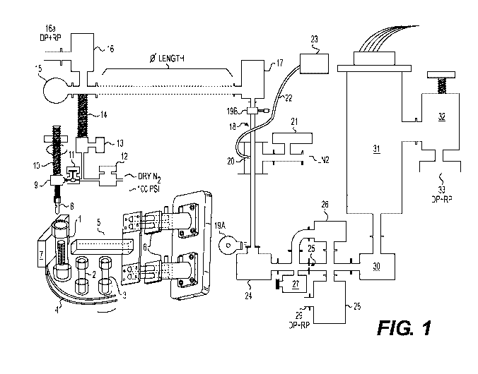
[0011] Figure 1 is a representation of an illustrative device/system of the
invention for
analyzing both the compressibility of samples and the volatile substance
content of such
samples through a non-selective trap of condensable gasses, a separate trap of
non-condensable
gasses, and mass spectrometry analysis of such compounds.
[0012] Figure 2 is an example of a data set obtained by performing methods
of the
invention in connection with petroleum well-associated cuttings.
[0013] Figure 3 provides another example of a data set obtained by
performing methods of
the invention in connection with petroleum well-associated cuttings.
[0014] Figure 3B provides a simplified, stylized view of select data shown
in Figure 3.
[0015] Figures 4A is an illustrative plot of oil, water, and oil saturated
water in connection
with a vertically oriented petroleum well.
[0016] Figure 4B is a simplified representation of key data provided in
Figure 4A.
[0017] Figure 5 provides yet another example of data obtained by performing
methods of
the invention on cuttings.
[0018] Figure 5B provides a simplified representation of select data
presented in Figure 5.
[0019] Figure 6 is a representation of a type of petroleum-associated
geologic formation
that can be identified and characterized by use of methods of the invention.
CA 03046972 2019-06-12
WO 2018/111945
PCT/US2017/065921
4
[0020] Figure 7 provides a plot of acetic acid measurements in a geologic
formation
against resistivity log data to identify petroleum associated regions in
sandstone
formations/sands.
[0021] Figure 8A and 8B provide a plot of multiple hydrocarbons at
different depths to
analyze the nature of petroleum deposits in a geologic formation.
[0022] Figure 8C provides a stylized representation of data associated with
a particular
type of geologic deposit that can be characterized by methods of the
invention.
[0023] Figure 9 is an illustrative representation of mapping a region of
sites using the
method of the invention to characterize a larger area comprising multiple
drilling sites.
[0024] Figure 10 is another plot of data obtained using methods of the
invention including
hydrocarbon data, oil saturated water, and other data elements used to
identify and characterize
deposits within a geologic formation at different depths.
[0025] Figure 10A is a simplified representation of key data patterns in
Figure 10.
[0026] Figure 11 provides a representation of two data sets for different
formations/sites
that can be differentially analyzed by methods of the invention.
[0027] Figure 12 provides an illustration of a well site device for
frackability/compression
analysis of cuttings allowing for real time/near real time steering of a
lateral well.
DETAILED DESCRIPTION OF THE INVENTION
[0028] The invention described herein provides various types of devices and
methods for
analyzing the contents of hard mineral-based materials, such as rock samples
taken from
geologic formations. One key use of these methods and devices is the analysis
of the drill
cuttings from petroleum wells for the contents of certain compounds in such
cuttings or that
can be obtained from such cuttings, which in turn provide information about
the geologic
material associated with the cuttings. However, the methods and devices of the
invention are
not limited to such applications and settings and can be applied to other
settings, as will be
discussed further herein.
[0029] In a primary aspect, the invention described herein provides a
method for
analyzing volatile substances in a material comprising the steps of (a)
providing an
analyzable sample of a material containing an analyzable amount of one or more
volatile
substances, (b) permitting the release of fluid (e.g., gas) containing the
volatile substances
from the material, (c) optionally subjecting the sample to one or more forces
to aid in the
release of the fluid, (e) optionally trapping the fluid by contact with a
media, in an
analyzable amount (an aliquot), (d) optionally isolating the fluid from the
material, (el)
applying energy or one or more forces to the aliquot so as to cause volatile
compounds in
the aliquot, if present, to form other chemical substances (energy-treated
gas(ses)) in a
CA 03046972 2019-06-12
WO 2018/111945
PCT/US2017/065921
predictable manner and/or (e2) releasing volatile substances from the aliquot
as trap-
released fluids in a predictable sequence, and (f) analyzing the chemistry of
one or more
trap-released fluids and/or energy-treated fluids.
[0030] The inventive methods described herein can be practiced with any
suitable
material containing any suitable number and/or suitable number of any suitable
type of
volatile substances. Suitability in this respect means that the volatile
substances are
amenable to analysis by the methods and/or devices of the invention, which can
be
determined by the principles described here or through application of routine
experimentation. A volatile substance in the context of the invention is a
material that will
take the form of a gas under the conditions in which the method is performed.
Conditions
relevant to whether a material is in the form of a gas at a particular time
include the pressure
the material is under at the time. In one aspect of the invention, at least
one volatile
substance is released from the material at atmospheric pressure. In another
aspect, at least
one volatile material analyzed by the method is released from the material
under a vacuum
(a pressure lower than atmospheric pressure ¨ i.e., a pressure of less than
about 760 Torr or
1.013x10⁵ Pa) or significantly more of the material is released under a vacuum
than at
atmospheric pressure (such as at least about 2 times, at least about 3 times,
at least about 5
times, at least about 10 times, at least about 20 times, at least about 30
times, at least about
50 times, or at least about 100 times atmospheric pressure).
[0031] In a particular aspect, the method includes analyzing at least one
volatile
substance that is released from the material under low vacuum conditions. Low
vacuum
conditions mean pressure conditions ranging from about 760 to about 25 Torr or
1x10⁵ to
3x10³ Pa (in this document each disclosure of a quantity modified by modifiers
such as
"about" is to be construed as simultaneously providing the corresponding exact
disclosure
and each disclosure of a range is to be construed as disclosing each unit of
the same order of
magnitude as the end points of the range, e.g., a disclosure of the range of 1-
5 also is to be
construed as disclosing the numbers 1, 2, 3, 4, and 5 individually). In
another exemplary
aspect, the method includes the step of analyzing at least one volatile
substance that is
released at under but close to 1000 millibars, such as about 40 millibars to
about 950
millibars, e.g., about 50 millibars to about 900 millibars, about 100
millibars to about 800
millibars, such as about 150 millibars to about 750 millibars, or any
combination of such
low and high-end points.
[0032] In another context, the method also or alternatively includes
analyzing at least
one volatile substance that is released from the material under medium vacuum
conditions.
Medium vacuum conditions mean pressures of about 25 Torr to about 1x10' Torr
(3x10³ to
1x10"' Pa). In another aspect, the method includes analyzing at least one
volatile substance
CA 03046972 2019-06-12
WO 2018/111945
PCT/US2017/065921
6
that is released from the material under a pressure of about 50 millibars
(e.g., applying one
more pressures of about 20-80 millibars, such as about 30-70 millibars) and
still another
aspect the method comprises performing an analysis on an aliquot obtained by
extraction at
one or more pressures in the range of about 30 millibars to about 10
millibars, such as about
25 millibars to about 12 millibars, e.g., about 20 millibars to about 15
millibars, or any other
combination of such low and high end points.
[0033] In another aspect, the invention also includes analyzing at least
one volatile
substance that is released from the material under high vacuum conditions.
High vacuum
conditions mean about 1x10' to about 1x10⁹ Torr (1x10"' to 1x10' Pa). In
another
respect, the invention includes analyzing at least one volatile substance
released under
vacuum pressures of less than about 5 millibars, such as less than about 2
millibars, such as
less than 1 millibar. For example, in another aspect, the invention comprises
analyzing at
least one volatile substance released under vacuum pressures of about lx10"2
millibars or
less, such as about 1x10' to about 1x10⁻⁹ millibars.
[0034] In still other aspects of the invention, the method does not
comprise application
of high vacuum (such as those described above), which in one respect
distinguishes such
aspects of this invention from prior art methods which include or are
dependent upon the
application of high vacuum to perform analysis of materials. In still other
aspects, the
practice of the method of the invention lacks application of either any high
vacuum or any
medium vacuum in the release of volatile compounds. This distinguishes these
aspects,
among other things, from prior art methods, such as many forms of fluid
inclusion analysis,
which typically require application of high vacuum and/or medium vacuum.
[0035] The material also can be any material which can be suitably
subjected to the
methods of the invention. In one typical context the material is a geologic
material, such as
rock material, a mud, or a soil, or a drilling byproduct, especially drilling
mud or a drill cutting.
In the context of this invention terms such as "cuttings" and "drill cuttings'
means rock
fragments that are brought to the surface in a drilling operation (such terms
are generally
understood in the art). Typically, drill cuttings are rocks that are
maintained separated from
drill muds in a shaker table operation or similar separation process. Drill
cuttings can have any
suitable size. The size of cuttings produced at a well will depend on several
factors including
the geologic material being drilled through and the drill bit used, with more
modern drill bits
often forming smaller cuttings. Particle sizes of cuttings can be, for
example, as small as about
microns (e.g., about 10 microns or larger, about 20 microns or larger, about
25 microns or
larger, about 50 microns or larger, etc.), but typically the cuttings will
have particle sizes of at
least about 100 microns, such as at least about 150 microns, or at least about
200 microns (e.g.,
about 250 microns or greater), and may be significantly larger, such as up to
about 7.5 mm
(e.g., about 6.5 mm or less, about 6 mm or less, or about 5 mm or less).
Commonly, cuttings
CA 03046972 2019-06-12
WO 2018/111945
PCT/US2017/065921
7
that typically have a particle size of between about 0.5 mm to about 1 mm and
about 5 mm to
about 6 mm are used in methods of the invention. However, in a particularly
unexpected
aspect of the invention (as exemplified elsewhere herein) the method has been
performed using
very small cuttings that were produced in a coring process, which are
significantly smaller in
size than typical cuttings obtained in oil production or exploration. Thus,
for example, the
method can be performed with cuttings of about 100 microns to about 5 mm,
about 50 microns
to about 10 mm, about 25 microns to about 7 mm, about 25 microns to about 12.5
mm, about
50 microns to about 6.5 mm, about 0.2 mm to about 6 mm, about 0.25 mm to about
5 mm, or
about 0.5 mm to about 5 mm. These are exemplary ranges, and these endpoints of
any one of
these ranges can be interchanged with end points of any other range to create
other suitable
ranges in which to focus other exemplary methods of the invention.
[0036] "Drilling mud", "muds", or "drilling fluid" in the context of this
invention refers to
a material that is distinguished from cuttings. Drilling mud is material that
is at least initially
introduced to a well site and used by the operator of a drilling operation to
perform one or
more functions including providing hydrostatic pressure to prevent formation
fluids from
entering into the well bore, maintaining the temperature and/or "cleanliness"
of the drill bit (or
at least preventing overheating and/or obstruction), maintaining the
structural integrity of the
bore hole, and/or aiding in the carrying out of drill cuttings. Drilling muds
commonly will
contain materials such as bentonite, barite, or hematite and can be water-
based or oil-based.
Muds often are dense materials and thixotropic, meaning that they become more
fluid with
application of agitation. The nature of drilling muds and the differences
between drilling muds
and cuttings will be understood by those skilled in the art.
[0037] In a specific context, the material is rock or mud material that is
associated with
either exploratory drilling or production drilling for petroleum, natural gas,
or related materials,
however materials obtained from other activities such as exploratory and
production drilling
for economic mineral deposits and geothermal energy also or alternatively
could be used in
practicing the methods of the invention. The material also or alternatively
can be from other
sources than from natural geologic formations or other non-petroleum-related
geologic
samples, or even biological samples such as teeth, bones, and the like (e.g.,
food or biomass
from any type of living organism whether viable or non-viable). In this
respect, the methods of
the invention may have application in various forensic and/or intelligence
applications, for
determining the impact of processes on materials, the historical source or
modulation of
materials, and/or, for example, the origin of materials or other information
about the nature of
such materials. For example, in another context the material is construction
material, such as
material used in building of commercial buildings, bridges, roads,
construction sites,
antiquities, and the like. The methods also can be applied to other man-made
materials such as
CA 03046972 2019-06-12
WO 2018/111945
PCT/US2017/065921
8
ceramics and other types of materials used in the manufacture or construction
of other devices
and structures, such as semiconductors.
[0038] In one aspect of the invention, the samples selected for analysis in
the performance
of the method comprise, are substantially comprised of (i.e., more than about
20% of the
samples are), are primarily comprised of (i.e., more than 51% of the samples
are), consist
essentially of (are comprised of to a level that the amount of non-conforming
material does not
impact the nature of the total sample or sample set), or consist entirely of,
material that
substantially lack relevant fluid inclusions ("RFIs"). "Relevant fluid
inclusions" or "RFIs" in
the context of this invention refers to fluid inclusions that (1) contain one
or more materials
that are indicative of the presence of a substance in the material (at least
in the inclusions), such
as petroleum or petroleum-related substances (e.g., organic acids,
hydrocarbons, and the like,
such as acetic acid) and (2) the presence of such materials reflect the
present condition of the
material (in terms of the presence of the target substance). Samples may lack
relevant fluid
inclusions for a number of reasons, such as relevant fluid inclusions may have
never formed in
the material (e.g., shallow, unconsolidated, young sandstone oil reservoirs in
the Gulf of
Mexico) or the relevant fluid inclusions may have been destroyed by natural
and/or human
processes (e.g., meteorite impact or drilling with polycrystalline diamond
compact ("PDC")
drill bits). As indicated elsewhere, often fluid inclusions will contain
ancient fluids that often
do not reflect the present fluid content of the material. In certain cases,
relatively "young"
fluid inclusions can form in a material or older fluid inclusions may be
filled by relatively
"young" material that is present in a material. Such fluid inclusions can be
classified as RFIs.
Non-relevant fluid inclusions ("NFIs") may still provide relevant information
to understanding
the material, but they are less probative with respect to the fluid content of
the material than
RFIs. Substantially lacking RFIs means that less than 0.000005% of the volume
of the sample
is made up of target substance (e.g., petroleum) or target substance-related
fluid inclusions
(e.g., only about 0.05 ppm or less of the sample volume is made up of oil or
an oil-relevant
substance). In some cases the invention is practiced wherein the amount of
RFIs is even less,
such as 0.025 ppm or less, about 0.02 ppm or less, or even about 0.01 ppm or
less of the
volume of the sample is made up of target substance-containing or target
substance-relevant
fluids (in even further aspects the amount of RFIs in the sample is even less
such as about 20
parts per trillion of the volume of the sample or less, about 10 parts per
trillion of the volume of
the sample or less, about 5 parts per trillion of the volume of the sample or
less, or even about
1 parts per trillion of the volume of the sample or less. In still other
aspects, the sample or
some of the sample(s) analyzed contain no detectable amount of RFI. In some
cases, the
sample may contain more volume of fluid inclusions, however the fluid
inclusions will be
known to not be relevant in the sense that there is information that informs
the artisan that
material in the fluid inclusion is not indicative of the fluid content of the
material (e.g., the
CA 03046972 2019-06-12
WO 2018/111945
PCT/US2017/065921
9
inclusion is indicative of the presence of oil, but it is known from drilling
that the content of
the material reflects little to no oil being present in the material). In
certain aspects, the
material and/or the sample is or comprises a material that lacks materials
that will form a
sufficient amount, size, or type of inclusion to be relevant, such as many
shales or
unconsolidated/young sands, which commonly lack material that is hard enough
to sufficiently
form inclusions that can provide detectable levels of RFIs even if the target
substance is
present in the material. It is important to understand that the term "target"
in this and other
contexts of describing aspects of the invention can mean, but does not always
mean, a specific
substance that is expected to be present or that is sought by the analytical
methods of the
invention. Thus, for example, the "target" can be one or more unknown
materials that are in a
material, such as one or more substances that are included in drill cuttings
or other geologic
material but that have no known composition prior to the analysis.
[0039] In another aspect of the invention, the samples analyzed and/or the
material
comprise a low number of RFIs. For example, in a particular facet of the
invention the sample
is a collection of cuttings in which less than about 20%, less than about 15%,
or about 10% or
less, such as about 5% or less of the cuttings comprise RFIs.
[0040] In other aspects, materials or samples with fluid inclusions can be
included
intentionally and will be included commonly in the sample and/or material,
and, in such cases,
the method optionally can additionally comprise, as discussed below,
performance of other
methods on materials containing fluid inclusions taken from site and/or
included in the
samples.
[0041] The material and/or samples typically will include fissures,
fractures, pockets,
cracks, etc., which contain target materials of interest, such as volatile
hydrocarbons. Such
fissures, fractures, etc. (referred collectively herein as "target substance
pores" or "TSPs"), will
often desirably contain target substance or target substance-relevant material
(e.g., such as
organic acids and/or hydrocarbons that are indicative of the presence of
petroleum) that also in
some cases are (1) present in relevant amounts in the material (either in
fluid form or are
absorbed or adsorbed in the material), rather than material that are artifacts
of prior existing
conditions, as is the case with many NFIs, (2) are exposed to the surrounding
environment in
some amount (such as by being contained in a pore in the material that is
exposed to the
surrounding environment) (in other words are not completely sealed off from
the environment
as is the case with fluid inclusions), or (3) can be characterized in
satisfying both (1) and (2).
A "pore fluid" in the context of this invention means a substance that is
ordinarily liquid or gas
in association with the material, contains one or more volatiles, and is found
in a TSP and
satisfies conditions (1), (2), or (3) of the preceding sentence. In some
aspects, the invention is
characterized by analyzing one or more samples containing an analyzable amount
of pore
CA 03046972 2019-06-12
WO 2018/111945
PCT/US2017/065921
fluid(s) and/or by analyzing one or more samples containing an analyzable
amount of a pore
fluid-related substance.
[0042] In a set of particular aspects, the material consists of, comprises,
or is substantially
comprised of a geologic material that has not experienced significant enough
burial diagenesis
to have formed fluid inclusions. "Substantially comprised of' in the context
of this invention
means that a substantially majority, such as at least 65%, more often at least
75%, such as at
least 80%, at least 85%, at least 90%, or even at least 95% of the referenced
material or
composition is comprised of the component at issue. In particular aspects, the
material consists
of, is comprised of, or is substantially comprised of "young sands." In the
context of this
invention a "young sand" means recent, Pliocene, and Miocene-age sediments
(e.g., 0-5
million years of age). For such sands that are buried about 10,000 feet below
surface level or
less in a tectonically quiet area (an area with relatively few earthquakes),
RFIs will typically
not be present or will be substantially lacking, as described elsewhere
herein.
[0043] In yet another aspect, the sample and material comprise a "tight
carbonate"
material. A "tight carbonate" in the context of the inventive methods means a
material that
comprises a substantial carbonate portion (e.g., at least about 90% of the
material is comprised
of one or more carbonates), which exhibit low permeability (e.g., about 15
millidarcies or less,
about 10 millidarcies or less, or about 5 millidarcies or less). In one
aspect, the material is a
material that is not suitable for traditional Sw analysis, because electricity
cannot sufficiently
flow through the material to give proper signals required for traditional
resistivity-based SW
analysis. The methods of the invention also or alternatively can be applied to
similar types of
materials from other settings that have similar types of resistivity,
permeability, and/or
conductivity issues.
[0044] The material typically is obtained in an analyzable sample or
presented in an
analyzable sample. In a general sense, an analyzable sample can be any sample
that has the
necessary characteristics that allow it to be analyzed using the specific
conditions of the
inventive method to be practiced with the material. Skilled persons practicing
this invention
will be able to select such materials based on the other conditions of the
method, the teachings
provided here, especially in view of routine experimentation and other known
principles. For
example, the size of the sample must be of sufficient size to provide enough
material to be
analyzed. Additionally, the sample typically is handled in a way so as to
preserve material in
the sample to allow volatile substances to be released therefrom upon
application of the
force(s) to be applied in performing the method of the invention. Other
conditions and features
of collection, storage, and/or handling of the sample may be selected so as to
maintain the
structural and/or chemical stability of the sample and volatile compounds
contained therein.
The sample also typically should be sufficiently free of materials that might
interfere with the
analysis. For example, the sample typically is collected and maintained in a
manner such that
CA 03046972 2019-06-12
WO 2018/111945
PCT/US2017/065921
11
it is substantially free of material from other sources that might
"contaminate" the sample by
causing it to provide false information about the location it is taken from
and its contents.
[0045] In still another aspect of the invention, the sample is obtained
from a process that
comprises the use of an oil-based mud. In general, drilling muds may be water-
based or oil-
based. Oil-based muds often can create difficulties for analytical methods
such as fluid
inclusion analysis methods known in the prior art. Those methods typically
require application
of high heat and/or vacuum, such as, e.g., in a vacuum oven, applied over a
long period in
order to deal with samples obtained with oil-based mud drilling processes or
risk interference
from the oil base of the mud and/or the oil material used for washing the
samples. Such
problems also exist with respect to non-fluid inclusion analysis methods, such
as my other
prior inventions. Methods in which high temperature and/or vacuum is/are
applied to remove
oil-based muds can suffer from the problem of also removing any endogenous
hydrocarbons,
organic acids, and/or oil. The ability to analyze such samples with the
methods of the
invention is yet another advantageous aspect of the inventive methods
described herein.
Samples also or alternatively can be obtained from water-based mud drilling
operations, and in
some instances (as exemplified herein) samples can be obtained for a site that
was subject to
both oil-based mud drilling and water-based mud drilling.
[0046] As discussed elsewhere herein, samples may be sealed at or soon
following
collection. In such aspects, about 0.5% to about 5% of the volume of the
sample may be made
up of the target substance or target-related substance. For example, about
0.75%-about 3.5%,
such as about 0.8% to about 3%, about 0.9% to about 2.75%, or about 1% to
about 2.5% of the
volume of the sample may be made up of the target substance(s) (e.g., C5-C10
petroleum
hydrocarbons) and/or target substance-related materials. These amounts of
target-related
substances are typically higher than the amount than would be found in in
materials only
having such target substances or target substance-related materials in fluid
inclusions.
[0047] The amount of material collected or provided may be in excess of the
amount that
can be the subject of analysis at any time so as to provide assurance that
there will be enough
of the sample material to perform repeated runs of the method, etc. Any
suitable amount of
material can be used. A typical sample may be on the order of about 100 mg,
but may be as
low as about 1 mg, about 10 mg, about 25 mg, about 50 mg, or about 75 mg. The
maximum
size of the sample often is determined by either the sample container size
and/or the capacity of
the mass spectrometry analytical component of the device used in the method,
if present.
However, under the right conditions and using the right type of device samples
as large as 1 g,
g, 10 g or even larger may be suitable for analysis.
[0048] Typically, the sample will be collected from a material having a
relatively known
location. The location usually will include approximate depth information in
addition to
longitude and latitude coordinates. Often the location may be a site of
interest in petroleum or
CA 03046972 2019-06-12
WO 2018/111945
PCT/US2017/065921
12
mineral exploration, such as an expected or known oil well, an oil well that
has been
previously deemed non-productive, or a mineral mine, such as a gold mine.
[0049] In another aspect of the invention the sample is a fragment of a
core sample. Core
samples are commonly generated in oil exploration and related processes and
are well
understood in the art. Analysis of core samples is considered important
because of the
preservation of oil or other target substances in the material. However, the
process of
analyzing core samples is often very time intensive. Advantageously, methods
of the invention
can be used to, e.g., to analyze fragments of core samples much more rapidly
by, for example,
evaluating the hydrocarbon content of such core sample fragments.
[0050] In most aspects of the invention, the sample is collected, stored,
and provided in a
container. Such a "sample container" can be any suitable type of container for
maintaining
samples in the context of the method to be performed. In some aspects of the
invention the
sample is either directly analyzed from the sample container or is placed into
a different
analysis container prior to analysis. Sample containers can include or possess
certain features
that are advantageous in the performance of some of the techniques described
herein.
Typically, the sample container is enclosed and usually at least partially
isolated from the
environment (and preferably substantially if not completely or essentially
completely isolated
from the environment), so as to maintain some portion of the volatile
compounds in the sample
over time, allowing for the other steps of the method to be performed a period
of time after
collection (and storage). In specific aspects, the sample container is capable
of preserving a
majority of the volatile substances in the sample at the time of insertion
into the sample
container (and in some cases more than a majority such as about 65% or more,
about 70% or
more, about 75% or more, about 80% or more, about 85% or more, about 90% or
more, about
95% or more, or even about 99% or more (e.g., 99.5%, 99.9%, or more) of the
original
volatiles are maintained) for a desired period of time (which may be, e.g., 1
week, 2 weeks,
one month, three months, six months, or even a year or longer). The
maintenance of volatiles
in such instances can be under typical, limited, or special conditions (e.g.,
refrigeration or
freezing may be required or desirable in some cases, but in many cases samples
can be
maintained under a wide variety of temperature conditions without much
additional care). In
other aspects, the sample container need only be able to maintain a sufficient
level of volatiles
to be able to be tested in the method, which may be less than 50% of the
volatiles in the sample
when the sample was loaded into the sample container. In some cases, the
amount of volatiles
is more than about 65%, such as about 75% or more, about 80% or more, about
85% or more,
about 90% or more, about 95% or more, about 97.5% or more, about 99% or more,
or even
about 99.5% or more (such as about 99.9% or more) of the volatiles present in
the sample
when placed in the sample container are maintained. In some aspects samples
may be
CA 03046972 2019-06-12
WO 2018/111945
PCT/US2017/065921
13
maintained in the container with one or more substances that reduce the
likelihood of
biological activity that might reduce the probative value of the sample.
[0051] In one aspect, the sample container comprises a feature such as a
seal, wall, cap, or
the like (hereinafter simply referred to as a "seal", unless context requires
otherwise or unless
otherwise explicitly stated), which is selectively penetrable by a flow
channel device, such as a
needle, such that volatile substances in the container can be released when
the sample
container is penetrated without significant loss of such volatiles. Thus, the
seal is typically of a
material and construction such that it will not release volatiles upon
puncture or other
formation of passage through it to provide means for releasing the volatiles
to the other
components of the system used to perform the method. Methods for determining
the integrity
of the seal can be used optionally in the method, as described below with
respect to collapsible
portions of the container. Loss from or contamination into the container from
the puncture or
other type of opening of or passage through the seal will typically be non-
detectable or will be
of very small amounts (e.g., less than about 1%, less than about 0.25%, less
than about 0.1%,
or even lower amounts).
[0052] In another aspect, the methods, systems, and devices can be
practiced with
containers that comprise a puncture-free method/step and/or puncture-less
component/system
or device for providing access to sealed volatile substances inside a sealed
sample container.
For example, in one facet the invention provides a system and method in which
a sample
container, such as a sample tube, is able to be selectively open to the
system, such as facets
wherein the sample containers are sample tubes within an enclosed autos ampler
and the
remaining portion of the system comes into fluid communication with the
container/sample
upon positioning of the sample tube into a position in which the open end of
the sample
tube/container is allowed to interface with an entryway to the remainder of
the device/system,
typically, for example by means of an automates vacuum sealing connector,
which may, e.g.,
cause an 0-ring to be tightened between the system and the open sample tube,
thus sealing the
tube to the system without any puncturing or any needle passageway. In this
kind of facet, the
system/device does not permit significant loss of contents from the sample
tube in the system,
as described elsewhere herein with respect to other sample containers (e.g.,
less than about 5%,
less than about 3%, less than about 1%, less than about 0.5%, or even less
than about 0.2% of
the contents are lost after placement into the sample container, in this case
in the
system/device).
[0053] In another aspect, the sample container also or alternatively
comprises sufficient
space beyond that which is occupied by the sample itself, such that some
portion of the
container can be filled with released volatiles. Accessible space also often
is provided for the
needle or other channel forming member or device to allow access into the
sample container,
in aspects where a sealed container is provided. Thus, about typically about 2-
20%, such as
CA 03046972 2019-06-12
WO 2018/111945
PCT/US2017/065921
14
about 3-15%, e.g., about 4-10% of the container, when sealed, is left as open
space providing
space for gas and also for flow channel device entry. The container may have
more open space
before sealing to also provide room for the seal (e.g., about 5-25% of the
container may be
designed to be open before the sealing).
[0054] In still another aspect, the sample container also or alternatively
comprises a
portion that is designed to be modifiable under certain conditions, such as
being collapsible
under mechanical pressure, such that the force of any sufficient mechanical
pressure applied to
the sample container can be transferred to the sample and thereby cause or
increase the release
of volatile substances, preferably without disrupting the structural integrity
of the sample
container in any manner that would cause release of any amount or any
significant amount of
volatiles that are released in the container (e.g., less than about 1%, less
than about 0.25%, less
than about 0.1%, or less than any detectable amount of volatiles are released
from the
application of force on the collapsible portion of the sample container)
and/or causing the
contamination of the container space (and volatiles contained therein) with
substances from the
surrounding atmospheric environment (such as air in the laboratory). The
method can
comprise monitoring pressure in the container or pressure in the container as
connected to the
analytical device, as one measure to make sure that no loss and/or
contamination is occurring
due to leaks. Other methods also or alternatively could be performed to ensure
that such leaks
of the container are not occurring, such as analyzing compounds in the
environment around the
container using conventional methods. As noted above, such techniques also can
be applied to
ensuring the integrity of other aspects of the sample container or other
elements of the system
that are used in the practice of the methods.
[0055] In typical and preferred aspects, the sample container is
specifically adapted for use
in one of the inventive devices described elsewhere herein for performing the
various methods
of the invention. Features that the sample container typically will comprise
in order to be
suitable for use in such devices include (1) a penetrable seal which is
comprised of a seal
material that is both (a) inert with respect to and (b) is at least
substantially if not entirely
impervious to the sample material and volatile materials contained therein (by
"inert" it is
meant that the material will not chemically react with the volatile materials
and the sample
materials, and does not give off volatiles under the conditions in which the
method is
performed, thereby modulating the analysis), and (c) is adapted in shape and
size to seal the
body of the container with respect to transmission of gasses and other
materials that might
partially or entirely interfere with, corrupt, or diminish the effectiveness
of the analysis, and,
preferably, and (2) a body comprised of a material that can be subjected to
forces to be used in
the method for drawing out of volatile materials, which in preferred aspects
includes crushing
of the sample container (and materials within the container) (e.g., the sample
container body
comprises or is composed of a material that is crushable under the force used
by the device,
CA 03046972 2019-06-12
WO 2018/111945
PCT/US2017/065921
allowing the sample of the material to also be crushed while releasing
volatile materials from
the sample into the container, the sample container being constructed in such
a manner and of
such materials so as to not be compromised, and so as to not lose its sealing
properties on
being crushed as discussed elsewhere). The principle of inert material
discussed in this
paragraph also typically applies to all elements of the sample container and
other elements of
the system used in the practice of the method. Thus, for example, tubing,
trapping devices, and
analytical devices incorporated into the system will similarly be selected
based on being inert
with respect to the sample and volatiles expected to be present and subjected
to analysis.
[0056] In certain aspects, the method comprises multiple rounds of
crushing, such as
crushing the sample container by application of crushing and/or squeezing or
compression
forces, typically from different directions. In still a further step, the
method comprises
restoring the container, at least partially, to its original shape after
application of a crushing
step or multiple crushing steps. The step of crushing or compressing samples
can be
performed at any suitable time. In one aspect, the step of crushing is
performed after the
application of other forces that promote the release of one or more volatile
substances from the
sample. In another aspect, the step of crushing or compressing the sample is
performed prior
to the application of other forces on the sample to promote the release of
volatiles, such as the
application of pressure to the sample. In still other aspects, as described
elsewhere herein, the
step of compressing the sample can be performed independently of extracting or
releasing
volatile compounds (and vice versa).
[0057] The preferred sample container is at least partially or relatively
flexible in design to
allow for capturing a variety of sample types under a variety of conditions.
Methods of the
invention can vary considerably in terms of pressure, temperature, gas
content, and other
relevant factors. The sample container and other elements of the system
typically are selected
to be able to operate under a wide variety of such conditions. Pressure
conditions are provided
elsewhere herein that can help characterize such suitability. Temperatures
used in practicing
methods of the invention can also vary considerably, especially where high
temperatures are
used to remove material and freezing is used as a trapping method. In this
respect, the overall
system, including the sample container, may see temperature ranges from about -
273/-270
degrees C ("degrees C" herein means degrees Centigrade) to about 500 degrees
C, such as
about -195 degrees C to about 200 degrees C. In many aspects, the temperature
in the system
will not exceed or even possibly not reach 100 degrees C. In other aspects,
the temperature in
the system will not exceed or possibly not reach 50 degrees C, particularly in
the sample
container. By remaining at such temperatures more affordable materials can be
used in the
practice of the method. Also, these extreme temperatures may not be reached in
all parts of the
device. For example, heat may be applied to the sample container, but freezing
temperatures
may only be applied to the trap device.
CA 03046972 2019-06-12
WO 2018/111945
PCT/US2017/065921
16
[0058] The flow channel or needle is used to penetrate or otherwise form a
passage for the
flow of gasses from the sample container (or more particularly in typical
embodiments a
needle is used to penetrate a seal component of or associated with the sample
container). In
embodiments comprising the use of a needle, the size of the needle typically
is selected such
that it provides sufficient flow of volatiles from the sample container to the
rest of the system
but is not so large as to cause puncturing of the seal and release of seal
material (or other
portion of the container) into the interior of the sample container. A needle
used in the
methods herein can have any suitable configuration of inlets (holes) to
receive the gas. A
single hole, placed in the side, or two holes, placed on each side, of the
needle, is typical. Side
placement of the needle can help ensure that the needle inlet does not become
clogged after
passage through a seal or sidewall of the container. A type 5 needle (by
Hamilton), for
example, provides such a balance with respect to exemplary devices described
herein.
[0059] As noted above, sealed samples can be stored for significant periods
of time and
still be successfully analyzed using the methods of the invention. Some
volatiles can be
trapped in hermetically sealed voids in solids, such as fluid inclusions in
rocks. In some
embodiments, such volatiles can be analyzed years or decades after the sample
is collected.
The volatiles hermetically sealed in the solid can be released by crushing the
solid, or by
thermally heating the solid until the volatile filled voids decrepitate.
[0060] Other volatiles can readily escape from their solid, liquid or
gaseous host. Such
volatiles include oil, water, and gas in pores in drill cuttings or core, or
within the drilling mud
used by the well. It will typically be desirable that such solid and liquid
samples are sealed as
quickly as practically possible to permit the most representative analyses of
the oil, water, and
gas in the Earth's interior. As demonstrated and discussed elsewhere herein,
the methods of
the invention can be practiced with old, exposed materials, in which some or
even significant
loss has occurred, but better results are often obtained with samples that are
sealed within a
short period of time from the sample reaching the surface or being exposed to
changed
atmospheric conditions that would allow for release of relevant substances.
[0061] In one aspect the inventive methods are practiced without
application of a
significant vacuum or pressure on the sample prior to performance of the
method. My prior
inventions and other prior art methods often will apply significant vacuum or
pressure and/or
significant temperature to samples prior to analysis of the materials. The
lack of such a step in
certain aspects of this invention is yet another way in which such aspects are
significantly
distinguishable from the prior art.
[0062] While sample containers that can be crushable or otherwise
compressible are often
preferred, a large variety of sample containers may be adequate for samples
that do not require
mechanical disruption (e.g., glass vials, graphite tubes, or other containers
that are
impermeable and inert) in the practice of certain aspects of the inventive
methods. Thus, for
CA 03046972 2019-06-12
WO 2018/111945
PCT/US2017/065921
17
example, if there is to be no mechanical disruption either glass vials or
sealed metal tubes can
be used as sample containers. Various hoses made of rubber or other polymers
might also or
alternatively suffice if they can be hermetically sealed. Even Mylar or
plastic bags may suffice
for some applications. In some aspects of the invention containers also can be
comprise or
primarily, nearly entirely, or entirely be made from carbon fibers. Indeed,
any container that
can be hermetically sealed might be sufficient, depending on the nature of the
bulk material
being captured.
[0063] Commonly, the sample container comprises a septum or a cap (e.g., a
synthetic
rubber or nitrile cap) that is inert and through which a suitable flow channel
device such as a
needle can be readily passed while maintaining the seal's integrity. In such
aspects, the
volatiles purged from the sample will enter the inlet lines through the
needle. Such elements of
the sample container are optional. In another exemplary embodiment, the sample
container is
sealed using a compression fitting that can be automatically applied, with
subsequent rupture
of the sample container to release the volatiles into the system's inlet.
Another approach that
may be more appropriate in some instances would be to insert the entire sample
container into
a hermetically sealed chamber that is attached to the inlet system, followed
by subsequent
rupture of the sample container to release the volatiles. The sealed sample
container could be
introduced automatically one at a time through an appropriate port, or an
individual sample or
multiple samples could be preloaded and sealed into part of the inlet system.
[0064] If the sample is to be crushed and is on the exterior of the inlet
system connected by
a needle through a septum, cap, or some other means, such as a remotely
controlled
compression fitting, it can be desirable that the container can be crushed
without leaking, and
that any motion of the sample during crushing does not break the seal between
the sample
container and the inlet system. The selection of parameters for sample
containers, seals, other
elements of device, and compression/crushing methods in general will be
selected such that a
seal is maintained and there is no undesirable loss of volatiles or material
or contamination
thereof. A brass cylinder sealed on the bottom with a neoprene plug and sealed
on the top with
a nitrile cap, for example, can be a suitable sample container. However, other
metals and other
sealing methods may be employed in the sample container or systems/methods of
the
invention. For instance, a brass rod could be partly drilled out to make a
vessel sealed on the
bottom, thereby eliminating the need for the neoprene plug. Similarly, the cap
could be made
of a variety of compounds, however Nitrile has very good sealing properties
for hydrocarbons
and most other volatiles.
[0065] It is typically important that if a cap is used to seal the sample
container that it can
be hermetically sealed to the body of the sample container. This can sometimes
be achieved
by simply having the cap's resting diameter be sufficiently smaller than the
tubes diameter so
that the cap needs to be stretched over the tube or fit into the tube that
forms the body of the
CA 03046972 2019-06-12
WO 2018/111945
PCT/US2017/065921
18
sample container. Stretching in this manner might by itself typically result
in a sufficient seal.
If not, then additional methods must be employed to affect a hermetic seal
between the cap and
the tube, such as applying a compression device such as a hose clamp or zip
tie or a metal ring
having a diameter greater than the tube but less than the diameter of the cap
when covering the
tube, around the outside of the cap. Other methods of sealing the cap to the
tube can include
applying glue, or epoxy, or wax, or grease, or some other sealing substance
between the cap
and the tube. It is also possible instead of a cap to use a septum crimped to
the top or some
other part of the sample container for a needle to pass through, or even a
polymer plug, such as
a neoprene plug used to seal the bottom of sample containers. For a sample
container that is
secured to the inlet system by an outer compression fitting, or some other
means such as a
screw fitting as on a hose (or a threaded cap), that is a larger than a needle
can form a channel
or flow path between the sample container and the inlet system. Such a sample
container
adapted to be in direct material communication with a wider diameter inlet
system can be
sealed using a wide variety of sealing material including metals, polymers,
glass, even such
exotic means as a salt or sugar plug, glue, or other adhesive or sealing
material. The sealing
material typically will make a hermetic seal after the sample is captured up
to the time it is
ruptured, and must be amenable to rupture after attachment to the inlet
system. Similarly,
sample containers that are loaded entirely into the inlet system generally
will be hermetically
sealed following loading of the sample, and usually will maintain that
hermetic seal until
somehow ruptured or made permeable to the substance(s) of interest at the
appropriate time
inside the inlet system.
[0066] As exemplified by the foregoing passages, it can in some aspects be
advantageous
and/or important that the overall system (sample container, inlet, or other
elements of the
system) are configured and constructed such that the overall system maintains
its integrity,
particularly with respect to the sample and volatiles released therefrom, upon
the application of
any forces applied in the method, such as any crushing force. An example of
such an approach
is the use of a needle-associated slug, as exemplified elsewhere herein. In
aspects where
application of a crushing force causes parts of the sample container to move,
become
deformed, or otherwise become displaced, such movement may permit the hole
that the needle
passed through to become enlarged, which might, if not addressed, allow
undesirable release of
materials from and/or contamination of the system/sample container. A slug
associated with
the needle, such as by use of a compression spring placed around the needle,
forcing intimate
contact between the slug and the cap or seal, can assure the user that any
such expanded hole
formed in the cap or seal will still not permit such release or contamination.
However, other
approaches can similarly be used to ensure that the entire sample
container/device system
maintains the integrity of the material, depending on the configuration of the
device and
sample container (and steps of the method) and any released volatiles and the
invention is not
CA 03046972 2019-06-12
WO 2018/111945
PCT/US2017/065921
19
limited to this slug/spring approach. For example, if high temperature is
applied to the sample
container, the sample container and inlet may be configured and composed such
that the
application of such high temperature does not allow the formation of any
cracks or openings
that would similarly allow for undesirable contamination or release.
[0067] In one aspect, the crushing of a sample container and sample
contained therein is
used to assess the ductility (and/or porosity) of the sample and,
correspondingly, the material.
In a method in which a material of relative standard strength (in terms of
crushability under a
relatively fixed amount of crushing force) (such as by using the same quality
of material in the
same thickness, etc., within very small variations (e.g., about 10% variation
or less, such as
about 5% variation or less, such as about 1% variation or less in thickness
and other relevant
characteristics), is employed with a standard measure of sample (again, given
the ability to
have similar variability in the amount), the amount of collapse of the
container, reflecting also
the crushability of the sample, can be correlated to either the strength of
the material and/or the
ductility of the material (and/or porosity of the material). Such methods can
be advantageous
where the method is performed in connection with oil fracking or similar
methods in which
ductility of the material is a very important feature of the material.
[0068] Mapping the ductility of samples versus measured drilling depth in
vertical well, or
in a horizontal well, can provide information as to which sections of rock are
most likely to
have low risk of fracking failure. Fracking failure occurs when the rocks that
have been
hydraulically fracked do not have sufficient mechanical strength to maintain
the induced
fractures open following the injection of a proppant, usually sand. This
aspect of this invention
therefore is termed "frackability", as an advantage of this aspect of the
invention is permitting
practitioners of the method to map those sections of rock drilled by a
petroleum well that will
maintain open fractures following fracking and proppant injection. This can be
especially
critical nearest to the borehole, since if the fractures near the borehole do
not remain open, no
or only a very diminished amount of oil and/or gas can be produced.
[0069] One realization of this aspect of the invention is to measure a
container, such as a
sample tube as described herein loaded with cuttings, after squeezing with a
known force, with
a micrometer or other appropriate measuring device. Such a method can be
performed
manually after the sample has been squeezed, or can be done automatically as
part of the
analytical process using a device such as a linear translator that
mechanically monitors how far
the pneumatic pistons are extended after squeezing the sample is completed, or
a device such
as a laser ranging instrument, also to measure the total extension of the air
piston, or other
squeezing means, after the sample is totally squeezed to its final thickness.
[0070] Real time measurement of the squeezing process by an appropriate
measurement
means allows additional information to be collected that provides useful and
necessary
information for the design of a optimally successful fracking job. This
includes measuring
CA 03046972 2019-06-12
WO 2018/111945
PCT/US2017/065921
how the air piston or other squeezing means deforms the sample as a function
of time and/or
the amount of pressure applied. The sample deformation may be relatively
rapid, or relatively
slow. The deformation may be a smooth continuous process, or may be a series
of
discontinuous forward lurches. Also of interest is how far the piston is
pushed back by the
sample after the pressure is released from the air piston, that is how much
does the sample
recover. The collection of these data during the squeezing process will allow
for the
calculation of various parameters vital to a successful fracking job,
including Poisson's Ratio
and Young's modulus.
[0071] Analyses of these parameters using the current state of art in the
industry usually
requires the expensive acquisition of a conventional core, or rotary sidewall
cores, followed by
expensive and time-consuming measurements at a laboratory usually some
significant distance
from the well. Often it is months after the well is drilled before the results
of these other
measurements are known.
[0072] Frackability from petroleum drilling cuttings can be rapidly
determined either in
the lab or on the well site. Turnaround time for transport of samples to the
lab followed by
analyses can be less than 24 hours. This is fast enough for the data to be
used in deciding the
final manner in which the well will be completed, such as what zones will be
perforated, or
where a horizontal lateral will be landed following the drilling of a vertical
pilot hole.
[0073] Even more timely results can be had by measuring frackability of the
well site
while the well is drilling. This can be done by manually collecting samples
and then loading in
an instrument at the well site for analyses. In another aspect of the
invention, frackability can
be determined at the well site using an automatized instrument that collects a
sample of drill
cuttings and squeezes them and monitors the deformation. Such an automated
apparatus
would not require loading the cuttings samples into a container. The cuttings
can fill a
collapsible compartment in the well site frackability apparatus. Following
filling of said
compartment with cuttings the squeezing mechanism of the apparatus squeezes
the cuttings
while the amount and systematic of the deformation of the sample is recorded
using a linear
translation or other type of measuring meter. The data thus collected would
then be stored on a
computer, and can be instantly integrated with other drilling parameters
generated by other
instruments on the well, including logging while drilling tools, such as gamma
ray logging
while drilling, rate of penetration, weight on bit, mud log shows, etc.
[0074] Real time frackability data can be combined with other real-time
data to determine
the optimum way to drill the well. The data can be used to help steer lateral
horizontal wells to
stay in the optimum formation.
[0075] In one aspect, the invention provides a method for analyzing the
frackability
(ductility or hardness) of a material, such as a geologic formation, which
comprises the
steps of (a) providing one or more analyzable samples of the material, (b)
subjecting the
CA 03046972 2019-06-12
WO 2018/111945
PCT/US2017/065921
21
sample to one or more forces that are capable of compressing material of a
given hardness
or ductility, and (c) determining the amount of compression of the sample
caused by the one
or more forces. The analyzable sample typically, but not necessarily, will be
from or
associated with a petroleum well or petroleum exploration. The most basic form
of the
frackability method is distinct from prior approaches used to assess hardness
of a geologic
material, which either depend on scratching (e.g., the classic Mohs scale
testing) or
penetration of a point of the material or point contact with a surface of the
material (such as
by using the Schmidt rebound hammer), although such methods can be combined
with the
basic frackability method. In one aspect, the compression force is applied to
at least an
entire side of the sample. More typically, the compression force will be
applied to multiple
sides of the sample contemporaneously (within 2 minutes, within 1 minute,
within 10
seconds, within 5 seconds, within 3 seconds, or within 1 second of each
other), and, most
often, simultaneously. Frequently, the compression force(s) will be applied
isotopically,
that is to say that it/they will be applied to all sides of the sample
contemporaneously or
simultaneously. Where advantageously combined with other methods of the
invention, the
compression study will be conducted in a compressible container, as
exemplified elsewhere
herein. The sample often is either a cutting or taken from a core sample
associated with a
petroleum well or petroleum exploration. Thus, in many aspects the size of the
sample will
be the size of a cutting, as explained elsewhere herein. In one aspect, the
method is
performed on cuttings that are associated with petroleum-associated mud. In
other aspects,
the method comprises washing the sample prior to crushing.
[0076] A further distinction in the typical application of the frackability
method and
methods of assessing hardness of geologic materials in the prior art is that
the frackability
method, especially when applied to cuttings, is applied to a large number of
materials (at least
10, typically at least 20, and often more, such as at least 25, at least 30,
at least 40, at least 50,
or more) that are obtained from different depths and/or different locations
within a relative
zone of depth, and frequently such materials are brought to the surface within
the relatively
short amount of time that is required for petroleum drilling (e.g., about 1
day to about 12
months, such as about 1-300 days, about 1-250 days, about 1-240 days, about 1-
200 days,
about 1-180 days), such that the samples comprise a number of samples obtained
during this
period (e.g., a majority of the samples are obtained within 200 days of each
other or at least 20,
at least 30, at least 35, at least 40, at least 50, or more, of the samples in
the analysis are
obtained within at least 240, at least 180, at least 120, at least 90, or at
least 60 days of each
other). Currently, assessments for tracking suitability have typically made
using either (1)
minerology assessments, which determine the mineral structures present in the
drilling area or
potential drilling area through sampling, (2) x-ray diffraction methods to
similarly assess the
geologic content of the area (within the detection limits of that method), and
(3) assessing the
CA 03046972 2019-06-12
WO 2018/111945
PCT/US2017/065921
22
total organic content of the exposed area of the material. These practices can
be combined
with the compression frackability methods provided by this invention, in
certain aspects, to
provide additional information about the material. However, in another aspect,
compression
frackability can be performed as an assessment method without employing any of
these
methods.
[0077] A collection of samples evaluated in the frackability, such as
cuttings, can
consist entirely of samples obtained from locations in the material that are
at least about 0.5
feet apart, and typically (but not necessarily) up to about 100 feet apart
from one another
(e.g., they can be from depths of a well that are at least 0.5 feet apart, at
least 0.75 feet apart,
at least 1 foot apart, or even further apart, such as at least 18 inches apart
or at least 24
inches apart), or the set of samples can substantially consist of (e.g., at
least 85%, at least
90%, at least 95%, at least 97%, or at least 99%) samples obtained from
locations
characterized by such differences, or the set of samples can be characterized
in that a
majority of the samples were obtained from locations having such differences
in space, or at
least a large proportion (such as at least about 10%, at least about 20%, at
least about 25%,
at least about 33%) of the samples were obtained from locations that have such
relative
spatial separation. In view of the possibility of lateral drilling the
separation between the
samples also or alternatively could be in the same relative zone of depth
(e.g., within the
same 500 ft, 400 ft, 350 ft, 300 ft, 250 ft, 200 ft, 150 ft, 100 ft, 50 ft, 30
ft, or 25 ft vertical
zone). In some aspects, multiple samples from approximately the same location
are tested,
but the set comprises a number of samples from different locations (e.g., at
least 10, at least
20, at least 30, at least 50, at least 100, at least 150, at least 200, at
least 250, at least 300, at
least 400, at least 500, at least 750, at least 1,000, or more samples, from
locations in the
material that are at least about 0.75 ft separated from each other). The
number of total
samples used in such a method will typically be greater than about 10, such as
greater than
about 20, and often can be significantly more samples, such as at least 50, at
least 100, and
can range from 10-5,000, 10-3,000, 10-2,500, 15-3,000, 15-2,500, 20-3,000, 20-
2,500, 25-
3,000, 25-2,5000, 25-2,000, 20-2,000, 10-2,000, 20-1,500, 25-1,500, or 10-
1,500 samples,
The total area of assessment can be significant, such as at least about 0.25
miles, 0.33 miles,
0.5 miles, 0.75 miles, 1 mile, 1.25 miles, 1.5 miles, 1.75 miles, 2 miles, or
more, in depth
and/or in horizontal area, reflecting lengths of modern petroleum wells. Thus,
the
frackability methods of the invention can provide a relatively fast map of the
suitability of
fracking a well site. In some respects, the entire analysis is conducted near
the well site
(such as within 200 feet of the well site). This can be achieved by using
devices of the
invention that compress material near the point of separation of cuttings and
muds, for
example, in petroleum drilling.
CA 03046972 2019-06-12
WO 2018/111945
PCT/US2017/065921
23
[0078] In some aspects, the compression frackability methods of the
invention are
combined with the other methods described herein for assessing hydrocarbon
content of a
material through release of volatile compounds, such as organic acids, which
may be released
using the methods described herein (e.g., application of gentle vacuum,
trapping, and
optionally analysis by sensitive methods such as mass spectrometry analysis).
In other aspects,
the frackability methods of the invention and the volatile compound analysis
methods of the
invention are practiced separately. Similarly, for the devices of this
invention, such devices
can comprise combined frackability and volatile compound analysis
components/systems, but
the invention also provides devices that comprise these functions as
individual features.
[0079] Some aspects of the invention, particularly those in which released
volatile
compound analysis will be performed as a part of the inventive method, are
characterized by
comprising a step in which sample material is stored quickly, and typically in
a sealed manner,
after arriving at the surface or otherwise being exposed to normal atmospheric
conditions. For
example, at an oil well site such a method can comprise collecting cuttings in
a sealed
container within a short amount of time after such cuttings reach the surface.
The time for
collection can vary with the nature of the sample, the method to be applied,
and the target
material(s) that are sought to be identified by the method. In an exemplary
aspect of the
invention, the samples are sealed in a sealable container in about 5 minutes
or less, but more
typically the time will be about 3 minutes or less, about 2.5 minutes or less,
about 2 minutes or
less, or even about 1.5 minutes or less, such as about 1 minute or less.
Samples can be subject
to washing immediately before sealing in a sealable sample container. Sample
washing can be
carried out by any suitable method. More generally, but not necessarily,
cuttings or other
materials typically are stored such that volatile compounds contained therein
are not lost below
limits detectable by the method. Volatile gasses and chemicals that rapidly
expand under
atmospheric pressure and non-constrained conditions, such as petroleum-related
hydrocarbons,
can be readily released from such materials once they reach the surface.
Accordingly, it is
advantageous to store materials to be analyzed such as cuttings within one or
more containers
that will ensure no release or little release of such substances during the
time the material is to
be stored and/or transported. In a preferred aspect, the materials are stored
in one of the
devices described elsewhere herein, and most preferably such a device is
configured to fit
securely within one of the analytical devices of the invention described
further elsewhere
herein, such as by mating with an inlet or by using a flow channel device,
such as one of the
needle devices discussed herein.
[0080] A filter material also can be added to the sample container. Any
type of suitable
filter material can be used. Suitability in this respect generally means that
substantially all
(e.g., at least about 95%, such as at least about 99%, or at least about
99.9%) of the material
(excluding the volatiles released from the material) is maintained in the
interior of the sample
CA 03046972 2019-06-12
WO 2018/111945
PCT/US2017/065921
24
container and does not enter or come into contact with the flow channel or
inlet. Simple filter
materials such as cloth materials and cotton pellets have been demonstrated to
be suitable for
this purpose. These materials, as with other materials used in the sample
container and
throughout the system must be inert with respect to reacting with volatile
chemicals and
emitting materials that would interfere with the analytical aspects of the
inventive methods.
[0081] In one aspect of the invention, the sample(s) that is/are analyzed
in the method is or
comprises a drilling mud. Muds have been discussed elsewhere herein. The mud
can be an
oil-based mud or a water-based mud. The analysis of muds typically means that
more than one
mud samples are taken. This is because material can be maintained in a mud
over several re-
uses of the mud (or passages of the mud to the drill bit point and the surface
where a sample
might be taken). Accordingly, samples may be taken at points that correspond
with an "up
mud" (mud arriving at the surface) and a "down mud" mud going back into the
well, which
will help to identify changes in the mud over time, aiding in the analysis of
the material
through studying the mud. In one aspect, the method comprises the analysis of
mud materials
and cuttings. In still another aspect the method comprises the analysis of mud
materials,
cuttings, and/or fragments of core samples, such as samples of each of these
categories taken
from a petroleum well or petroleum exploration site.
[0082] The material and sample are typically a solid (as in the case of a
cutting), but in
other aspects of the invention the sample and/or material is a liquid or a
gas, and in still other
aspects the sample and/or material is a mix of two or more of a solid, liquid,
or a gas, or a
combination of all three forms of material. For example, in an industrial
setting, samples can
be taken of the air to ensure that the amount(s) of certain compounds (e.g.,
benzene) are within
certain levels. In still another embodiment the method is applied to look for
seeping, such as
gasses seeping into and/or out of a geological formation. Geothermal activity
also can be
assessed by the method. In another aspect, the method can be practiced with a
liquid, such as
water, to assess the level of certain substances in the liquid (such as
contaminants in water
samples). As noted elsewhere the material can be of natural, synthetic, or
semi-synthetic
origin, and may be generated from a variety of origins and/or settings, such
as industrial solids,
soft materials, liquids, and air, or other gases.
[0083] In preferred aspects, the method is applied to analyze the volatile
compound
content of the material. Volatiles in rocks typically contain important
information used for
petroleum, geothermal energy, and mineral exploration and production.
Volatiles in rocks can
also be used to determine the suitability of quarried stone for road and
building construction.
Volatiles in rocks and soils may also provide information beneficial to
ecological and
environmental studies. Volatiles in solids that form as a byproduct of various
industrial or civil
processes, such as scales that can form in the casing of oil, gas, and water
wells, can provide
information that may help design processes to inhibit the formation of such
unwanted solids.
CA 03046972 2019-06-12
WO 2018/111945
PCT/US2017/065921
Volatiles in man-made solids such as bricks, concrete, ceramics, glass, and
plastics can be used
to ascertain problems in their manufacturing process, or to evaluate their
utility for various
applications. Volatiles that occur in solids that form in natural biological
systems, such as
bone, teeth, kidney stones, finger and toe nails, may provide insights that
could help to
maintain or improve the health of the individual or community from which these
solids
originated. Volatiles in softer tissues from plants and animals, including
humans, may also
offer diagnostic information that may be useful to the health of the source
organism. Such
methods may have application in testing in food safety testing, food
viability, food storage,
and/or shelf-life, or the like. Volatiles in industrial and natural liquids
also contain a wealth of
information that can impact the success and profitability of petroleum,
geothermal energy, and
minerals exploration and production; the efficiency and profitability, of
manufacturing and
other industrial processes; and the health and well-being of the environment,
organisms and
communities. Various explosive products may also have distinct volatile
signatures that could
be detected with the device described herein, thus volatile monitoring of air
or solids may have
benefits in keeping people, communities, the military, and law enforcement
secure.
[0084] In one aspect of the invention the sample is taken from an outcrop
and the material
comprises an outcrop. Outcrops are geologically important formations. In one
aspect,
outcrops (outcroppings) are used as a comparator to subterranean materials,
such as materials
obtained from a mine or drilling site. Such materials may also contain
evidence of materials
seeping to the surface.
[0085] The material typically is dry, but in some aspects of the invention
is moist or even
wet (e.g., in the case of a liquid or a mud). In some aspects of the invention
it can be important
to ensure that the amount of a liquid, such as water, in the material, is not
too high so as to
overcome the capacity of the mass spectrometry device. However, in general,
this is not a
limiting factor, and the skilled artisan will be able to assess if any such
situation arises.
As already noted herein, the material, and thus the sample, will typically
contain one or more
volatile substances that will either passively release or be released upon the
application of one
or more forces on the sample. In either case, a gas will be released from the
sample that
contains one or more volatile substances, although, as discussed elsewhere
herein, the sample
can also contain non-volatile substances, which may also or alternatively be
collected, and
considered, as part of the analytical aspect of the inventive method. The
nature of the volatile
substances contained in the sample can vary considerably and the inventive
methods can be
practiced with various types of volatile compounds. In specific aspects,
however, the sample
and material contain a significant amount of one or more specific target
substances. For
example, in the case of drill cuttings, taken from petroleum production of
exploration sites, the
sample will contain detectable amounts of one or more species of Cl ¨ C20
hydrocarbons and
related compounds that contain oxygen, nitrogen, sulfur or other heteroatoms;
organic acids
CA 03046972 2019-06-12
WO 2018/111945
PCT/US2017/065921
26
(e.g., Cl-CS organic acids, particularly C1-C3 organic acids, and most
commonly acetic acid,
carbonic acid, and/or formic acid); and/or one or more inorganic gasses, such
as hydrogen,
helium, carbon dioxide, carbon monoxide, water, nitrogen, argon, oxygen,
hydrogen sulfide,
carbonyl sulfide, carbon disulfide, and/or sulfur dioxide. In one embodiment,
the sample
comprises C1-C15 hydrocarbons, such as C1-C14 or C1-C12 hydrocarbons and the
method
comprises analyzing one or more of such hydrocarbons. In still another aspect,
the sample
comprises C1-10 hydrocarbons and the method comprises analyzing one or more of
such
hydrocarbons. In aspects that are often preferred the invention also or
alternatively is
characterized by the detection of acetic acid, carbonic acid, and/or formic
acid contained in the
sample or formed from application of one or more forces on the sample in the
practice of the
inventive method. In this respect, the sample can be characterized as
comprising one or more
compounds that form such compounds, or by having material that can form carbon
dioxide,
carbon monoxide, methane, and/or water.
[0086] In another facet, the inventive methods provided herein can be
characterized in that
such method comprises conducting an analysis of the sample for one or more
substances
containing a carbon chain of five or more, such as six or more, or seven or
more carbon atoms.
In some cases, the method comprises heating the sample or gasses to assist
with the analysis of
longer chain hydrocarbons or other carbon chain-comprising compounds, such as
hydrocarbons having a backbone of more than 10 carbon atoms. For example, the
method can
comprise heating the sample or gas (or the device containing either or both)
to about 130 C or
more, about 140 C or more, or about 150 C or more, to assist with the
analysis of such
longer-chain hydrocarbons. In this and other respects, the method can comprise
controlling the
temperature during which some or all of the process is performed, such as the
temperature at
which gasses are released and/or analyzed by the analytical processes of the
method. Such
methods typically can comprise heating the entirety of the system from the
inlet, through to the
trap, to the mass spectrometer, and through to the exit. In other aspects, it
is preferred that the
method is generally performed at room temperature, although in such aspects it
may also
comprise using freezing as a means for trapping volatiles and/or applying heat
to release
compounds from a freezing trap mechanism or media.
[0087] In some aspects, the invention is characterized by not creating new
volatile
compounds in the sample, such as forming volatiles from hydrated minerals
(where water is a
part of the crystal structure, such as silicate clay minerals; hydrated
oxides, such as brucite
(Mg0H2) and goethite (Fe0OH); and other water-bearing mineral substances such
as
hydroxyl apatite; etc.) or where, e.g., carbon dioxide is part of the crystal
structure (such as
calcite (CaCO3), dolomite (CaMg(CO3)2), and siderite (FeCO3)); and solid and
liquid
hydrocarbons not volatile as a gas under the analytical conditions in which
the methods of the
CA 03046972 2019-06-12
WO 2018/111945
PCT/US2017/065921
27
invention are performed, such as C20 alkanes or various bitumins or kerogens;
or any other
substance that is normally not a gas or normally emits a gas under such
conditions.
[0088] In practicing methods of the invention one or more gasses is/are
typically
released or extracted from the sample of the material. In some contexts, the
gas can be
released passively (without application of force or without application of a
significant
force); e.g., by exposing the sample or the container comprising the sample to
a release
channel or release passage, such as a needle or similar device which
penetrates the container
containing the sample. In other contexts, as noted elsewhere herein, the
methods also or
alternatively can comprise applying energy to the sample, such as by
mechanical force, e.g.,
crushing of the sample or crushing of a container that has a crushable portion
and that
contains a crushable sample. In either case, the gas or gasses are released
from the sample
of material and then are allowed to flow such that one of the further steps of
the method can
be performed on such gas. The amount of time required for the gas to be
release can vary
with the conditions of the method, including the material, whether or not
forces are applied
to the sample, the time in which gasses are permitted to be released from the
sample, and
the sensitivity of the analytical methods performed on the gasses. Using the
guidance
provided herein skilled artisans will be able to determine these conditions.
For samples that
are analyzed at atmospheric pressure without the application of force a time
of about 1
second may be sufficient, for example. Longer or shorter periods of time may
be suitable,
but such a relatively short period may be desirable. Longer periods may cause
the sample to
be under lower pressure conditions because of the relatively lower pressure
condition of the
device.
[0089] In many aspects of the invention volatile substances are extracted
from a sample by
subjecting the sample to various levels of vacuum. For some samples, important
additional
information is obtained by subjecting the sample to a range of increasingly
lower pressures, in
other words to increasingly higher levels of vacuum, and analyzing the
chemistry of each
individual aliquot extracted at each individual extraction pressure. This has
proven to be
especially useful for solids, particularly for various rock samples including
outcrop, core, and
cuttings samples as applied to the exploration for and production of oil and
gas. Depending on
the sample and the problem being addressed various other processes may be
applied to the
sample prior to any vacuum extraction, in between vacuum extraction steps, or
even during a
vacuum extraction step, as will be discussed further herein. In one example,
another process
that can be applied, and which is described elsewhere herein, is crushing or
squeezing the
sample or applying any process that mechanically disrupts the solid sample.
Other processes
that might disrupt the sample include sawing, or tumbling, or exposing to
vibrational energy at
any number of frequencies. Another process that could be employed is heating
the sample;
one effect of which can be disruption of the sample by thermal decrepitation
of fluid inclusions
CA 03046972 2019-06-12
WO 2018/111945
PCT/US2017/065921
28
and/or other structures in the sample. Chemical processes and/or application
of energy also or
alternatively may be applied to the sample in the performance of the method,
such as, for
example, applying an acid to the sample so as to dissolve certain substances.
It is also possible
that in some instances a combination of two or more of these or other
disruptive processes may
be usefully applied in the practice of the inventive methods.
[0090] The method also may include one or more steps performed before
release of
gasses, or between release of gasses (in methods in which there are multiple
release steps or
multiple samples analyzed). In one aspect, the method comprises purging some
amount of air
from the sample, e.g., by application of vacuum. In such embodiments the time
the vacuum
purge is applied will generally be such that the amount(s) of volatiles that
are purged with the
air is sufficiently small to justify the purging step. This may comprise, for
example, only 1 or
2 second application of vacuum pressure, so as to lower the pressure from
about 1000 millibars
to about 50 millibars (but these are only exemplary figures). However, such a
purging step can
be important where the presence of air as a contaminant will interfere with
the analysis. This
may be important with respect to analysis of older samples contained in open
environments.
[0091] In a further specific aspect, the inventive methods can comprise
purging the
sample, which may be a sealed sample, and replacing the purged air with
another gas, such as
argon, nitrogen, or helium, or any other suitable gas as determined by the
specific advantage
gained for the specific problem being addressed and the specific host solid
and specific
volatiles being analyzed. argon is typically preferred as nitrogen and helium
may be relevant
in the analysis of the sample.
[0092] These steps of purging (and optionally replacing) air or other
surrounding gas
provides a mean of removing potentially interfering substances in the air or
other gas in which
the sample is contained, which might provide false signals in the analysis
(e.g., confusing
methane with oxygen or nitrogen species found in air). Other methods of
accomplishing the
same goal may be available in the art and likewise suitable, but this method
is preferred in
many aspects of the invention. For example, in one alternative, the air or gas
in an inner
sample container is displaced with a liquid, such as a diffusion pump oil, and
the inner sample
container placed in a surrounding, outer container. The inner sample container
comprises or
typically is entirely made of a material that can be crushed or compressed by
application of a
force. A vacuum is applied to remove any air from the surrounding container,
creating a
vacuum condition in the space formed by the surrounding container, and the
entire sample
container sealed. A force that compresses or crushes the sample in the inner
container is
applied, breaching the inner container and releasing volatiles into the now
exposed outer
container. Such materials can then be subjected to further analysis in
accordance with the
inventive methods described herein with little risk of interference from
substances in air, etc.
CA 03046972 2019-06-12
WO 2018/111945
PCT/US2017/065921
29
[0093] The rapid purging of air from the sample, and rapid replacement with
argon or
other gas prior to crushing the sample can be particularly relevant in
analyzing samples
relevant to oil and/or gas exploration. Generally, these methods are applied
to older samples
maintained under open conditions, as there is a trade-off in terms of loss of
volatile substances
in applying the purging methods. Thus, for sealed samples, such methods may
not be
practiced.
[0094] Purging (and purging and replacing processes) can facilitate the
mass spectrometer
analyses of very small amounts of certain substances, such as methane, using
mass 15 for the
CH3 ion, by removing nitrogen and oxygen. The lower resolution of many
quadrupole mass
spectrometers makes it difficult to analyze trace methane using mass 15 in the
presence of
major amounts of nitrogen with a major peak on mass 14 and oxygen with a major
peak on
mass 16. Purging and replacement of air with other gases may have other
benefits.
Replacement of air with krypton, having mass 86, would solve the methane
interference issue
as does argon, but could also aid in the extraction of some recalcitrant
volatiles in the solid by
imparting a much greater amount of energy in collision with the lighter gases
present as the
sample's voids are evacuated.
[0095] Most purging steps are completed quickly, especially when the step
comprises the
removal of air in the system by means of quick vacuum (versus flowing of an
inert gas or a
combination of both types of steps). For example, in one aspect the purging
process is
complete in about 10 seconds or less, such as about 5 seconds or less, about 3
seconds or less,
or even about 2 seconds or less. In the case of a quick vacuum purge,
application of such a step
for less than about 3 seconds, such as less than about 2 seconds, less than
about 1.5 seconds, or
even 1 second or less can be advantageous. Another way to characterize such a
step in some
aspects is that the vacuum purge step results in a loss of less than about 5%,
less than about
2%, less than about 1%, or even lower losses (e.g., less than about 0.5%) of
the oil and with
respect to gasses the losses are less than about 10%, less than about 7.5%,
less than about 5%,
less than about 3%, or less than about 1% of the gas present at the time the
sample is
introduced to the system. Purging is typically performed prior to crushing or
squeezing of
materials, or other application of forces to the sample. At the well site,
samples may not be
purged as nearly all information can be converted into data, especially with
the use of control
sampling devices/systems that are used to calibrate the system (with respect
to gasses that are
at the site and not associated with the samples). For sealed samples, the
method also may lack
purging, as this may result in data loss. As such, purging steps are often
optional, but can be
useful when there is a determination that there could be a risk of an
interfering signal.
[0096] Depending on the problem being addressed by the analytical method,
it also or
alternatively may be advantageous to heat or cool the sample prior to volatile
extraction.
Heating or cooling of the sample can be performed alone or with crushing
and/or purging (or
CA 03046972 2019-06-12
WO 2018/111945
PCT/US2017/065921
purging and replacing the air or other surrounding gas). For instance, if
volatiles in water ice
were to be analyzed, the sample would need to be held at a cold enough
temperature to keep
the ice frozen during volatile extraction and any purging and gas exchange for
air preceding
crushing. A temperature of about minus 50 degrees Centigrade might be needed
in this
example to keep the ice from sublimating in response to the applied vacuum. A
similar
process could be advantageous in the analysis of gas hydrates, otherwise known
as clathrates.
[0097] Centrifuging also or alternatively can sometimes be an aid to
volatile extraction.
Centrifuging an upright sample prior to volatile extraction, for example, can
cause the vertical
stratification of volatiles in the container, gases would migrate to the top,
and oil would in
general form a layer on top of water. This can be particularly useful in the
analyses of volatiles
in drilling muds from oil and gas exploration and production wells.
Centrifuging following
crushing can sometimes also have similar advantageous effects.
[0098] After all preparatory processes, if any, are complete the volatiles
typically are
extracted from the sample by reducing pressure on the sample by exposing the
sample
container to an inlet system that is under static vacuum and is not being
actively pumped. The
inlet system typically is sealed off to vacuum pumps at this point in the
process, having been
previously evacuated by vacuum pumps. Pressure is reduced on the sample by
opening a valve
between the sample container and the inlet system allowing gas to pass from
the sample
through the needle or other flow channel device into the inlet system. During
a multi-stage
extraction, at increasing levels of vacuum for each extraction, the first
extraction results in a
resulting pressure on the sample and in the inlet system that is determined by
the gas pressure
in the sample and the sample container, the void volume in the sample
container, and the
volume of the static inlet system. Each collection of extracted gas(ses)
obtained by such a
method is referred to as an "aliquot" herein. Thus, for example, the first
extraction of a gas at
atmospheric pressure or a different pressure may be referred to as Aliquot 1,
with subsequent
aliquot numbers each increasing by one, so that a three stage analyses will
have Aliquot 1,
Aliquot 2, and Aliquot 3. In typical practice, Aliquot 1 is extracted at a
pressure of about 50
millibars. A typical Aliquot 2 is extracted at an initial pressure of about 5
millibars, and this
pressure for a typical Aliquot 2 is decreased by a period of active pumping
following initial
trapping of the more volatile gases to about 0.001 millibars or less (e.g., as
low as 0.0001
millibars or lower, or any range between about 0.001 millibars and 0.0001
millibars, such as
0.005-0.0005, 0.00075-0.00025, or 0.0009-0.0002 millibars). The step of
causing this
significant type of pressure drop in the system, device, or method of the
invention is
advantageous in methods in which a mass spectrometry analysis is performed on
the samples,
as mass spectrometry conditions typically require lower pressures than those
in which aliquot
extraction methods are performed in order to appropriately operate. Such
pressure conditions
will be known in the art (or provided by the mass spectrometry manufacturer)
and the
CA 03046972 2019-06-12
WO 2018/111945
PCT/US2017/065921
31
achievement of such levels of pressure can be achieved through any suitable
means, with many
such methods and devices being available.
[0099] As mentioned elsewhere, the methods of the invention can, in certain
instances,
include one or more steps in which potentially interfering gasses are removed
from the
released gas or the environment in which the gas is released. For example, in
one aspect the
invention can include the step of flooding the device in which the method is
performed with
an inert gas such as argon, so as to remove gasses from the device, which
might provide false
signals or results. Normal atmospheric gasses such as oxygen, nitrogen, and/or
both, for
example, can be substantially removed, or nearly completely removed, or even
entirely
removed (to detectable levels) by administering ("flooding") to the device or
a portion of the
device in which the method is carried out with such an inert gas. Such a
method also can be
used as a method for refreshing the device between samples. Where an inert gas
is used in
such aspects, the inert gas can be any suitable gas that does not chemically
react with the
sample and does not cause any interferences with the chemical analyses of the
samples'
volatiles. In other aspects, a non-gaseous material, such as a liquid can be
similarly used. The
atmospheric or other interfering gas can be purged from the device, component,
or
environment in which the sample is being analyzed by, e.g., rapid vacuum
extraction (e.g.,
applying a vacuum that is sufficiently strong to substantially or nearly
entirely remove the
purging inert gas for a duration of about 1 second or less). In another
aspect, the method can
comprise flowing an inert gas through the sample container or area to displace
the potentially
interfering gas. Such methods are not included in every application of the
inventive methods.
For example, where the method is performed on samples sealed at a collection
site, such as a
well site, such a step is typically not performed. However, such purging steps
can be useful for
analyzing the presence of target substances where such substances are or are
suspected to be
present only in very small amounts, such as with respect to methane and/or
helium in samples
that are associated with petroleum production or exploration sites.
[0100] Materials or methods also or alternatively can be used for removing
other
potentially interfering substances such as water vapor, for example, which is
relevant to
certain aspects of the invention in which water is formed and analyzed as a
method for
analyzing hydrocarbon content in samples. In one aspect, the invention is
performed in the
presence of a material that can capture essentially all, substantially all, or
a relevant portion
of the water vapor present around the sample that might be captured by either
the trap or
other tools for capturing substances used in the analytical method. For
example, the system
that is used for performing the method can comprise passages between system
elements that
are made of stainless steel, which promotes the absorption of water and thus
removes water
vapor contained in the gas content flowing through the system from reaching
the next stage
of the system.
CA 03046972 2019-06-12
WO 2018/111945
PCT/US2017/065921
32
[0101] The amount of volatile substances released from the sample, trapped
on the trap,
or analyzed by the analytical method of the inventive methods described herein
can
constitute any suitable proportion of the volatiles present in the sample, and
the amount
contained at each such stage in each of the aliquots obtained in multi-aliquot
methods of the
invention also can be any suitable amounts. Typically, most of the volatiles
are captured by
the method, such that at least about 90%, at least about 95%, at least about
97%, at least
about 99% of the volatiles (excluding water, and particularly with respect to
Cl-C10
hydrocarbons and similarly structured organic compounds) are extracted from
the sample,
by the practice of the methods of the invention. The efficiency of the system
typically also
is high with respect to trapping of gasses that are condensable on the trap.
Typically,
condensable gasses that can be captured by the trap are not retained in the
system in
detectable levels. However, as discussed elsewhere herein certain gasses will
not condense
on the trap or otherwise be trapped by the trap and must be subject to
handling by other
means to be captured and analyzed by the method.
[0102] To exemplify (and clarify), methods of the invention can comprise
analysis of a
single aliquot, for example a single aliquot obtained under gentle/low vacuum
conditions, or
in other aspects the method can comprise obtaining and analyzing a plurality
of aliquots
from one or more samples and/or that are obtained under different conditions.
For example,
one method comprises obtaining two aliquots per sample, wherein the first
aliquot is
obtained by application of about 50 millibars (e.g., 10-100 millibars, such as
15-95
millibars, 20-90 millibars, 30-80 millibars, or 40-70 millibars) for about 3
minutes (e.g., 1-
minutes, such as 1.5-8 minutes, 2-7.5 minutes, 2.5-5 minutes, or the like, in
some cases it
may be advantageous to perform the first aliquot extraction for shorter times
in this or other
contexts, such as 0.25-4 minutes, 0.33-3.5 minutes, 0.5-3 minutes, 0.5-4
minutes, 0.5-5
minutes, 0.5-2.5 minutes, 0.5-2 minutes, 0.75-3 minutes, 0.75-2.5 minutes,
0.75-2 minutes,
or another similar time interval) and a obtaining a second aliquot by putting
the sample
under pressure conditions of about 5 millibars (e.g., about 1-10 millibars,
about 2-8
millibars, about 3-7 millibars, or the like) for a period of about 10 minutes
(such as 5-15
minutes, e.g., 6-12 minutes, 6-10 minutes, 5-9 minutes, 6-9 minutes, 7-9
minutes, 7-10
minutes, or about 7 minutes, about 8 minutes, or about 9 minutes), with the
method
optionally including a step of crushing/squeezing the sample during one or
both aliquots,
such as crushing the sample at the start of the first aliquot extraction, as
described elsewhere
herein. In some aspects, shorter extraction times (e.g., less than about 5
minutes, less than
about 4.5 minutes, less than about 4 minutes, less than about 3 minutes, less
than about 2.5
minutes, less than about 2 minutes, less than about 1.5 minutes, less than
about 1 minute, or
even shorter periods. In such aspects the parameters of the system and the
method can be
adjusted to facilitate shorter extraction time, such as, for example, using a
relatively larger
CA 03046972 2019-06-12
WO 2018/111945
PCT/US2017/065921
33
diameter needle system for the passage of volatiles out of a punctured sample
container
(e.g., use of a needle of about 1/8th or about 1/16th of an inch internal
diameter as
compared to about a 32nd of an inch diameter needle). In another approach,
extraction time
and/or purging time of the system can be reduced by to passing a non-
condensable purge
gas through the sample.
[0103] In some contexts, it may be useful that the method of the invention
is performed
and/or the device of the invention is provided with a plurality of trapping
devices, which
may be of the same or different nature. Thus, for example, in one aspect, the
invention
includes a plurality of non-selective traps, such as a plurality of liquid
nitrogen traps. This
kind of system/device can be particularly advantageous with multiple aliquot
methods. In
such methods it can be possible that each aliquot or at least a subset of the
total number of
aliquots are associated with each trap. This can, among other things, speed up
the process
of performing multiple aliquot analyses, for example by exposing the aliquots
to the traps
separately or operating traps at different times, such that there is little
downtime in the
system in the event a trap needs to be cleaned, set, or re-set in between
uses. Where traps
with different functional properties are provided, using different traps can
enhance the
information obtained from the method, by providing different dimensions to the
analysis
(e.g., by combining one or more non-selective traps with one or more selective
traps, such
as GC traps).
[0104] As already noted, gasses released from the sample are released to a
system or
device in which the remaining steps of the method are performed. Typically,
the gasses
pass into the system or device through an inlet, which may be a portion of the
system or
device associated with a needle or flow channel as discussed elsewhere herein
or can be any
other suitable type of inlet. Thus, processes employed before and during
vacuum extraction
can include attaching the sample container to the inlet system before
initiation of vacuum
extraction and any ancillary processes. A number of processes can be used to
attach the
sample container to the inlet system. These are described in the section on
the various
possible configurations of the sample container. Our preferred sample
container is a sealed
brass tube with a hermetically attached nitrile cap on the top and a neoprene
plug in the
bottom. Using the typically preferred sample container, the sample container
is attached to
the inlet system prior to initiation of vacuum extraction by passing a needle
through the
nitrile cap. Other types of sample containers must be sealed by other
appropriate means to
the inlet system prior to initiation of vacuum extraction.
[0105] Another step of the inventive methods also or alternatively can
include applying
energy to either the gasses generated in the practice of the inventive
methods, which can
include either gasses directly released from the sample or gasses that are
released from the
trapping device or media of the invention (the "trap", as further described
elsewhere herein).
CA 03046972 2019-06-12
WO 2018/111945
PCT/US2017/065921
34
The amount of energy and type of energy applied to gasses in such aspects can
be in any
suitable amount and form so as to generate one or more other target substances
that, for
example, are more convenient for detection and/or analysis than substances
that were in the
gasses prior to application of the energy. For example, the methods of the
invention can
comprise a step of applying an energy source such as a source of light energy
to a gas,
thereby forming compounds from organic acids, such as carbon monoxide, water,
carbon
dioxide, methane, and the like, in amounts that are suitable for detection by
the analytical
aspects of the inventive methods. Carbon monoxide often is preferred as a
molecule for
detection in that it typically lacks potential competing signals which may
sometimes pose
issues for analyzing water or carbon dioxide. Carbon monoxide is generated by
the
breakdown of formic acid (HCOOH) to water (H20) and carbon monoxide (CO). This
reaction even occurs at about 1 atmosphere pressures, so much so that some
large bottles of
formic acid are provided with a vent that allows carbon monoxide to escape and
thus avoid
unwanted pressure build up in the bottle. In contrast, acetic acid (CH3COOH)
breaks down
to water (H20) plus methane (CH4), and carbonic acid (H2CO3) breaks down to
water
(H20) plus carbon dioxide (CO2). Carbonic acid is only stable in solution, and
has no
stable gaseous phase.
[0106] The amounts of organic acids released from materials, such as
cuttings, may be
very small, and their respective indicator break down compounds may be masked
by larger
amounts of these compounds being released as compounds existing as those
compounds in
the sample. In geologic samples this is especially true for water, carbon
dioxide, and
methane. This is not a usual problem for carbon monoxide as its natural
occurrence in
samples from oil and gas wells is minimal at best. However, carbon monoxide
can be
generated as a by-product of oil and gas drilling by the process known as -bit
burn- or -drill
bit metamorphism-. In a lab apparatus aspect of the invention, and related
methods of use,
some of the compounds derived from organic acids that are also present as
naturally
occurring interfering compounds, such as water and carbon dioxide, are frozen
to a liquid
nitrogen (LN2) trap. Carbon monoxide and methane do not freeze to the LN2
trap.
However, methane as a naturally occurring substance is common in rocks from
oil and gas
wells. Therefore, the presence and amount of methane in rocks from oil and gas
wells is not
an adequate indicator of precursor organic acids. Carbon monoxide is not at
all common as
a natural component of rocks from oil and gas wells. Therefore, the presence
of carbon
monoxide typically is a good indicator of organic acids. Thus, for example, in
one set of
aspects the inventive methods comprise detection of carbon monoxide, but not
methane or
at least do not comprise relating methane levels to overall levels of organic
acids in the
material associated with the sample/cuttings.
CA 03046972 2019-06-12
WO 2018/111945
PCT/US2017/065921
[0107] In certain aspects, carbon monoxide is monitored using the AMU12
fragment
formed by mass spectrometry analysis of carbon monoxide. In a more particular
aspect, the
method comprises performing a method in which carbon monoxide is a primary
indicator of
organic acids in the material, and is analyzed by evaluating the presence and
amount of the
AMU12 fragment formed by mass spectrometry performed on carbon monoxide, and
the
method is performed either free of any detectable amount of carbon dioxide or
in the
presence of an amount of carbon monoxide that does not result in a distortion
of the carbon
monoxide-associated AMU12 signal or the degree of the AMU12 signal that is
associated
with carbon monoxide. In some aspects, the amount of interference with the
AMU12 signal
from the presence of carbon dioxide in such a method is less than 25%, less
than 20%, less
than 15%, less than 10%, less than 5%, less than 2%, or less than 1%. In
settings where
carbon dioxide is present, the method can comprise either manually or
automatically
correcting the AMU12 signal data for the presence of carbon dioxide to obtain
a carbon
monoxide-associated AMU12 signal. In some aspects, the step of isolating
carbon dioxide
is handled by use of a trap that collects carbon dioxide, such as a liquid
nitrogen trap, in a
manner such that carbon monoxide and carbon dioxide are not in associated
aliquots (for
example, carbon monoxide in a lab device of the invention may be collected in
a non-
condensable gas state, whereas carbon dioxide is fixed to the liquid nitrogen
trap). In other
aspects the method of analyzing carbon monoxide level also or alternatively
comprises
analyzing the signal from AMU13 and/or AMU 16 and/or 28. In aspects where
carbon
dioxide is initially present but removed or substantially removed (e.g., by
removal of at least
85%, at least 90%, at least 95%, at least 97%, at least 99%, or more, of the
initial
concentration) as a part of the inventive method, a CO2 absorber, such as
DecarbiteTM,
also or alternatively can be used to reduce or eliminate any detectable levels
of carbon
monoxide in the gas or aliquot to be analyzed, Also or alternatively, a mass
spectrometer
based machine designed to detect trace amounts of carbon monoxide in cuttings
can be
designed to use any of the CO2 eliminating/reduction techniques described
herein and their
known equivalents in the art.
[0108] In another aspect, the method is performed under conditions in which
the
application of the energy also or alternative changes the pressure of gas
associated with the
sample or generated from the sample in a manner or amount that is indicative
of a chemical
change that identifies the presence of a target substance or a target-related
substance (such
as carbon monoxide).
[0109] It is important to note that while in many aspects of the inventive
methods mass
spectrometry analysis is an important component of the inventive method, such
a step is not
always included (and often is not included) in these methods. Rather, other
analytical steps
can be performed to identify the presence of the target substance or target-
related substance.
CA 03046972 2019-06-12
WO 2018/111945
PCT/US2017/065921
36
For example, a carbon monoxide meter or measuring device can be used to
directly measure
the formation of carbon monoxide in a petroleum-related sample, thereby
indicating the
presence of organic acids prior to application of the energy, and thereby
further indicating
the presence of oil-related substances in the sample (and material). Also or
alternatively,
simply measuring the pressure in the gas related to the sample can be
indicative of a
relevant change, such that a pressure gauge, meter, or device can be used in
the method,
alone or in combination with mass spectrometry analysis (carbon monoxide
monitoring also
can be combined with mass spectrometry analysis or all three methods can be
combined in
the analytical method).
[0110] Such methods of the invention also can often be desirably performed
in the field,
such as directly at a well or exploration site. Accordingly, whereas many
aspects of the
invention comprise the use of small samples, in these and other methods larger
amounts of
materials may be used, such as cup sized containers, pint size containers,
quart size
containers, gallon size containers, or containers that have volumes of about 5
liters or more,
about 10 liters or more, about 20 liters or more, or even about 30, 40, or 50
liters or more
(e.g., a large bucket of sample material). For example, a large container of
cuttings can be
collected from where cuttings are deposited near a well site (e.g., in
association with a well
site shaker table) and then directly used for analysis with such methods.
[0111] In addition to or alternatively to light energy, other suitable
types of energy can
be applied to the sample in order to modify the gas content for direct
evaluation or to see if
pressure increases, indicating a change in content that is indicative of the
presence of the
target substance in the material. Examples of other types of suitable energy
include heating
methods, vacuum, other forms of radiation (e.g., UV light), and the like. In
another aspect,
the method also or alternatively can comprise performing a chemical reaction
to form such
compounds that are indicative of the presence of the target substance in the
material. The
amount of energy applied in practice of the method can be any suitable amount
to achieve
the desired change. In one exemplary aspect, the sample is heated to about 400
degrees C
or greater for a period sufficient to generate indicative target compounds
(e.g., carbon
monoxide) from organic acids present in the samples.
[0112] Methods of the invention can and often do include the step of
subjecting a
sample of the material, such as one or more cuttings associated with one or
more geologic
formations, to one or more forces to cause the release of a first gas
containing an analyzable
amount of one or more volatile substances. The force that can be applied to
the sample can
include a pressure force, such as a high pressure (positive pressure) or a
vacuum;
temperature; chemical reaction; application of radiation (such as microwave,
which might
be used to remove water from material); and/or physical forces, such as
crushing or
vibration (e.g., ultrasonic vibration). Other forces that can be applied
include dehydrating
CA 03046972 2019-06-12
WO 2018/111945
PCT/US2017/065921
37
the sample by heat or chemical means, applying temperature to the sample,
applying
mechanical pressure on the sample, mechanically rupturing some or all the
sample,
subjecting the sample to a chemical reaction, or a combination of any or all
thereof,
optionally in addition to applying one or more levels of vacuum and/or
pressure to the
sample.
[0113] In one aspect, the force is a vacuum pressure, such as the vacuum
pressures
described above. For example, a low pressure can be applied to a sample of the
material as
a means for causing one or more volatile substances to be detectably released
from the
material (or a vacuum can be applied that would increase the release of one or
more volatile
substances or gas(ses) from the sample if such a volatile substance is
present). The precise
amount of vacuum will vary depending on the material and other conditions of
the method.
Commonly the pressure will be below atmospheric pressure but greater than
about 3x10⁻⁴
millibars. In another aspect, practicing a method of the invention comprises
applying a
vacuum to the sample at a pressure that is between atmospheric pressure and
about 1x10⁻³
millibars. In yet another aspect, the method comprises applying a vacuum to
the sample at a
pressure that is between atmospheric pressure and about 25 x 10-3 millibars.
In still another
facet, practicing a method of the invention comprises applying a vacuum to the
sample at a
pressure that is between atmospheric pressure and about 1x10⁻³ millibars. In
yet another
aspect, the method comprises applying a vacuum to the sample at a pressure
that is between
atmospheric pressure and about 1 x 10⁻² millibars. In still another sense,
methods of the
invention can comprise a step of applying a vacuum to the sample that is
defined by a
pressure of between about 1 to about 100 millibars.
[0114] In other particular aspects, the method comprises applying a
positive pressure to
the sample. A positive pressure can be any pressure that is in excess of
ambient
atmospheric pressure and that results in a measurable release of desired
gas(ses) (at least
under conditions in which volatile substances that form such gas(ses) are
present in the
sample). Positive pressure can be applied by any suitable means, such as, for
example,
using a piston. The method can include one or more applications of positive
pressure, or the
combination of application of positive pressure with any of the other methods
described
herein for aiding disrupting the sample and/or extracting fluids from the
sample. The
specific pressure applied will depend on the other conditions of the method,
such as the
nature of the material and whether other forces are applied to the sample. In
one example, a
pressure of about 400 to about 4000 pounds is exerted on the sample (e.g.,
about 1000
pounds to about 3500 pounds), although higher pressures also can be exerted by
using
certain methods available in the art, such as hydraulic pistons.
[0115] In another aspect, the method also or alternatively includes
application of a
physical force, such as crushing, abrasion, thermal decrepitation, grinding,
and/or drilling.
CA 03046972 2019-06-12
WO 2018/111945
PCT/US2017/065921
38
For example, materials can be loaded into a sample container comprising a
crushable
portion, such as a crushable sidewall, and the sample container can be
subjected to crushing
so as to promote the release of volatile materials. For example, as discussed
elsewhere
herein, samples that are or that comprise cuttings can include hydrocarbon
materials
contained in small fissures, pores, and other structures, which are
distinguishable from fluid
inclusions, by their exposure to the environment and/or in that they are
characterized in not
being hermetically sealed in an inclusion. These formations in geological
material, which
are also represented in cuttings taken from such material, can contain
hydrocarbons, such as
petroleum-related hydrocarbons, which are held in the geologic material.
Application of a
physical force, such as crushing, can assist in releasing such materials from
such
formations. Selection of the parameters for these methods will vary with the
nature of the
material, other parts of the analytical method, etc. A typical exemplary
method of the
invention will comprise crushing samples, such as cuttings, by about 400
pounds to about
4000 pounds, which can be achieved using some of the exemplary devices
described herein.
[0116] It should be noted that in certain aspects of the invention no force
is applied to
the sample. In other words, just the exposure of the material to a release
channel, such as a
needle that penetrates a container in which a sample of the material is
contained, can allow
the gas to be exposed for performance of the next step of the method or to
flow to either
another container, portion of a device of the invention, or the like, wherein
such other steps
can be performed. For example, in one aspect, the gas that is released from
the sample will
flow to a gas trap device, such as a liquid nitrogen gas trap, such that a
portion of the gas
becomes trapped in the trap and thereafter can be released in a predictable
manner.
[0117] In one embodiment, methods of the invention are characterized by the
collection
of the sample in a sealed container and by the subjecting the sample for an
initial period to
approximately the same pressure (e.g., within 90%, 95%, 99%, or more of the
same
condition) or exactly the same pressure (at least within limits of detection
and/or condition,
such as at atmospheric pressure without respect to natural fluctuations in
such pressure) at
which the sample was sealed in the sample container, such that a majority of
the volatile
materials are not lost when released from the container. Often this means that
the sample
will initially be subjected to atmospheric pressure.
[0118] In another aspect, in addition or alternative to crushing the
sample, by the
methods described elsewhere herein the methods can comprise mechanically
rupturing
some or all of the sample, subjecting the sample to a chemical reaction, or
performing a
combination of any thereof, alone or in combination with application of
crushing,
compression, or the like. In another facet of the invention it is
characterized by the lack of
any step that comprises application of heat (e.g., an increase of temperature
of about 25% or
more, about 35% or more, about 50% or more, about 75% or more, about 100% or
more,
CA 03046972 2019-06-12
WO 2018/111945
PCT/US2017/065921
39
etc.) for a period of more than about 12 hours, such as more than about 6
hours, more than
about 4 hours, or more than about 2 hours.
[0119] In one aspect of the invention the method comprises isolating or
"trapping" some
portion of the gas released from the sample by contacting the released gas
with a "gas trap"
(which may also simply be called "a trap").
[0120] "Trapping" means that the trapped gas is collected and maintained or
held in a
device, medium, and/or location. Trapping in the context of these aspects of
the invention
typically occurs in a releasable manner, and commonly the gas is trapped in a
manner such
that parts of the trapped gas can be released from the trap in a predictable
manner, such as
when some kind of change is made to the condition of the trap. For example, in
one aspect
the trap is a material that bonds to some portion of the gas and the gas is
released by
changing the conditions of the bonding, for example, by increasing the
temperature.
[0121] In a preferred aspect, the trap is a cryogenic trap, such as a
liquid nitrogen trap,
which traps gasses through freezing of volatile compounds onto a surface that
has been
cooled by liquid nitrogen or other cryogenic methods thereby freezing the
volatile
compound to the trap device or trap media. In such embodiments, the method can
include
the step of releasing of volatile compounds from the trap due to warming of
the trap,
thereby releasing volatile compounds from the trap in a predictable sequence
for further
analysis and/or treatment. Freezing traps can be operated under any suitable
conditions.
Typically, conditions will be selected based on the properties of the material
to be trapped
by the media or device used in the inventive method. In one aspect, the trap
is a material or
device that is cooled to about minus 50 degrees C or less in the performance
of the method
(e.g., about minus 100 degrees C or less, such as about minus 150 degrees C or
less, such as
about minus 190-200 degrees C, although in some cases colder temperatures can
be
obtained and employed). Commonly, the cryogenic trap will be cooled to such a
temperature prior to the exposure of the gas released from the sample to the
trap. In this
respect, as in some of the preferred devices described below for practicing
the inventive
methods, there may be one or more controllable valves that are used to
controllably expose
the sample-release gas to the trap, and the method correspondingly will
include the step of
exposing the trap to the sample-release gas in a controllable manner, after
such cryogenic
cooling.
[0122] Other types of traps may also be suitable for performing steps of
the inventive
methods. In one case the trap may be selective, in that it is either capable
(or more capable)
of selectively binding to certain materials and/or selectively not binding
certain materials.
In one case, for example, the trap is selected such that it is selective for
not trapping water,
carbon dioxide (or other compounds that might interfere with parts of the
analysis, make
analysis more difficult and/or less accurate), and/or make analysis take
longer or cost more)
CA 03046972 2019-06-12
WO 2018/111945
PCT/US2017/065921
and/or one or more organic acids, particularly if analysis of the organic
acids is also a part
of the method.
[0123] Typically, however, the trap used in the inventive method is a non-
selective trap,
at least with respect to target substances of interest. The term "non-
selective trap" in the
context of this invention typically means that the trap binds to all or
substantially all of the
volatile compounds present in the sample or all of the relevant volatile
compounds that are
present in the sample. The operation of such a non-selective trap can be
contrasted with a
selective trap, such as may be found in a gas chromatograph ("GC"), which
binds to a
certain compound or a class of compounds, but does not bind to other
compounds. This is
not to exclude application of GC technology in performing certain aspects of
the invention,
as aspects of the invention in which GC technology is used are described
elsewhere herein
and, as noted above, in certain cases selective traps, such as using a GC
material (or set of
such materials), could be part of a trap component of the invention, or could
constitute the
trap.
[0124] In aspects where the gas is subject to a trap, the material
contained in or that is
otherwise bound to the trap can be considered to form an "aliquot" that is
used for further
analysis according to various aspects of the invention.
[0125] As noted above, gas trapping devices, media, or systems, which can
be used in
various contexts of the invention, can be either selective or non-selective.
In one aspect, the
gas trapping device is a non-selective trap, capable of capturing gas
containing a number of
different types of volatile compounds, such as a cryogenic trap which freezes
volatile
compounds to fix them to a media. A liquid nitrogen trap is an example of such
a cryogenic
trap.
[0126] The gas released from the sample (or "first gas") will be allowed to
contact the
trap for any suitable period of time. The optimal time of contact will vary
with the trap, the
gasses that are present or expected to be present, and other factors. For
cryogenic traps,
such as the liquid nitrogen trap described above, the time of contact between
the trap and
the volatile substances can be relatively short, such as less than about a
minute, and
commonly less than about 45 seconds, usually less than about 30 seconds, and
often as little
as about 15 seconds, about 10 seconds, or less than about 10 seconds (such as
7, 6, or even 5
seconds) will be suitable. In certain cases, the trap will comprise a pumping
function, such
as in the case where the trap is a cryogenic trap/pump, which may occur by the
action of
freezing substances to the trap. In this respect, having conditions that cause
freezing
quickly can be important, as such quick freezing removes volatile compounds
from the
atmosphere surrounding the sample, which will, in turn, cause more volatile
compounds to
be released from the sample (as the system works towards equilibrium).
CA 03046972 2019-06-12
WO 2018/111945
PCT/US2017/065921
41
[0127] However, the entire period that gasses released from the sample are
exposed to
the trap will be significantly longer than these short periods, such as a
period of about 10
minutes or longer, for example about 15 minutes or longer, about 20 minutes or
longer,
about 30 minutes or longer, about 40 minutes or longer, or about 60 minutes or
longer. The
amount of time of exposure depends on the pressure applied, the nature of the
sample, and
other factors. When, for example, seeking to release and analyze more
refractory substance
in the sample and/or when dealing with a particularly difficult sample
material, longer times
of application may be required, such as about 15 to about 30 minutes. However,
in other
aspects, the amount of time that is applied is about 10 minutes or less, such
as about 8
minutes or less, about 6 minutes or less, or even about 5 minutes or less.
[0128] In some cases, where the method is performed with repeated cycles,
the cycles
can vary in terms of the amount of time in which gas is exposed to the trap.
For example, in
the first cycle of a method the time may be relatively shorter, such as less
than about 10
minutes, where there may be more gas readily available in association with the
cycle,
whereas in subsequent cycles, where it is more difficult to extract gas from
the sample, a
longer period of time may be employed, such as about 10 minutes or longer, so
as to permit
the second cycle gasses to sufficiently bind to the trap.
[0129] In aspects in which an extended time prior to the warming of the
liquid nitrogen
trap is provided, the extended time is not solely to provide more time for the
gasses to bind
to the liquid nitrogen trap, but, rather, such an extended time can provide
for improved
extraction or liberation of volatile species from the sample. Thus, the
liberation of volatile
gasses from a sample can be, at least in some respects, considered to depend
on the
variables of the nature of the sample, the nature of the volatiles, the forces
applied on the
sample to promote release of such volatiles, and the time given to permit such
release and/or
collection of gasses. It is often preferred that all volatile fluids that are
gaseous in the
sample are collected prior to exposure to any vacuum. Where the sample
contains volatile
liquids, the application of vacuum to the sample, such as after "passive" (non-
vacuum)
collection of gaseous volatile substances from the sample, can be desired,
inasmuch as such
application of vacuum may lead to boiling of substantially all or all of such
liquids, or at
least result in the boiling of a substantial proportion of such volatile
substances (at least
20%, at least 30%, or at least 33% of the amount); a majority of the
substances; a substantial
majority of the substances (at least 66.66%, at least 75%, at least 90%, at
least 95%, at least
99%); or at least a detectable amount of such substances. In any case, the
boiling of such
volatiles that are normally liquid (at atmospheric pressure and typical
ambient temperature)
will render such boiled substances or boiled fraction of such substances
gaseous. The
length of time required to achieve a desired level of boiling of liquid
substances in the
sample is dependent on factors similar to those described above with respect
to release of
CA 03046972 2019-06-12
WO 2018/111945
PCT/US2017/065921
42
gaseous volatile compounds, but will primarily depend on the weight of the
substance
(heavier materials typically require longer to boil). Application of longer
periods of
vacuum, and resultant boiling, can, thus, result in the conversion of a
significant amount of
liquid volatiles into gaseous species for analysis in accordance with the
inventive methods
described herein. Thus, the certain aspects of the invention that comprise
application of
extended periods of time for release of gaseous volatile substances from a
sample and/or
application of vacuum to boil liquid volatile compounds in a sample provide
the inventive
methods a unique advantage over the prior art in that more of the volatile
substances in a
sample can be fully analyzed by allowing the time required for more of the
volatile liquids
to be released and/or captured.
[0130] In one aspect of the method, the change in temperature used to
release gas
species from the liquid nitrogen trap is performed in less time than flash
warming methods
used in gas chromatograph (GC) methods that also use liquid nitrogen trapping.
Such GC
methods use "flash" or rapid warming applied to a liquid nitrogen trap used in
the GC
method, which release many, most, or substantially all of the gasses trapped
to the liquid
nitrogen trap at once. GC methods also require that all of the gasses to be
analyzed enter
the GC media simultaneously, such as a trap if used in the method, nearly
simultaneously,
as the presence of all of the gasses to be analyzed at the same time is
necessary for the
effective performance of such analytical methods. These limitations are
typically not
required (or desired) for the inventive methods described herein, and as
described elsewhere
a gradual warming of the liquid nitrogen trap over a more sustained period of
time to permit
for the predictable release of trapped gasses is a common aspect of methods of
the invention
that comprise a trap, such as a liquid nitrogen trap. Also, this negates the
need for any kind
of separation of gasses other than the warming of the liquid nitrogen trap in
these aspects of
the invention. Thus, in another facet of the invention, the invention lacks
any step of
molecular selection, such as molecular distillation or similar method, being
performed on
the substances to be analyzed in the method.
[0131] In some aspects, a relatively high vacuum can be applied to a trap
or applied in
the device or system used to carry out the inventive method such that the trap
is under
vacuum conditions for a period of time. For example, in some cases where a
relatively high
vacuum is applied to a sample that vacuum also may be applied through other
parts of the
system, including the trap. In other aspects, the method also or alternatively
comprises a
method in which vacuum is applied to capture non-condensable gasses and remove
such
material from contact with the trap (or to at least substantially achieve such
a state).
[0132] In certain aspects, such as where relatively high vacuum is applied
to the trap or
in the system such that a vacuum condition is present at the trap for a
period, it can be
advantageous to continue to reinforce the trap media or device with whatever
substance is
CA 03046972 2019-06-12
WO 2018/111945
PCT/US2017/065921
43
used to trap the target gasses, such that gasses that might be easily/readily
released from the
trap are maintained in contact with the trap. For example, in the case of a
liquid nitrogen
trap the method can comprise continuously applying liquid nitrogen to the trap
while the
vacuum condition is present so as to retain substance of interest (e.g.,
ethane, ethene, etc.)
trapped into the trap until they are ready for release in a predictable
manner.
[0133] Another action that can form part of the methods of the invention is
the step of
isolating the aliquot from the sample. Commonly, once gasses are collected
from the
sample to form an aliquot, that aliquot can then be isolated from the sample,
such that the
remainder of the analysis of the method or at least that step or part of the
method is
conducted on the aliquot without further collection of gas from the sample for
the collection
of the present aliquot (or if this is the final aliquot or only a single
aliquot is being collected
for the particular application of the method). This method of isolating can be
performed for
many reasons and using any suitable technique. Where devices of the invention
described
elsewhere herein are used in the practice of the method, for example, one or
more valves
may be engaged, which results in isolating the gas of the aliquot from the
sample. The
method also or alternatively can include the step of isolating the trapped
gasses from access
to other components of the device or system in which the trap is situated. For
example,
where the method is performed with a device of the invention that comprises
(a) a sample
holding unit, (b) a gas trap, and (c) a mass spectrometer, the method
typically will comprise
the step of isolating the gas trap from both the sample holding unit and the
mass
spectrometer for one or more periods of time (e.g., isolating the trap from
the samples after
a sufficient passage of time and/or application of conditions necessary to
collect gasses from
the sample and isolating the mass spectrometer until it is time to release the
gasses from the
trap to it for analysis).
[0134] In aspects of the invention in which one or more gasses released
from the sample
are subjected to a trap to form an aliquot, the method typically includes the
step of releasing
volatile substances from the aliquot as trap-released gasses in a predictable
sequence. For
example, where the sample is comprised of one or more drill cuttings obtained
from an oil
well site, gas is obtained from cuttings, either passively or by the
application of one or more
forces, such as mechanical crushing and/or application of one or more vacuum
pressures on
the sample, and then subjected to a trap, such as a liquid nitrogen trap. Much
of the gas
from the cutting samples will be captured by the trap. Allowing the trap to
heat, either
passively, or, more typically through the application of heat, directly or
indirectly, to the
trap, will allow for volatile substances in the gas that are frozen to the
trap to be released in
a predictable manner.
[0135] A "predictable manner" means that substances such as individual
volatile gasses
or mixtures or other types of volatile gas species are released from the trap
in a manner such
CA 03046972 2019-06-12
WO 2018/111945
PCT/US2017/065921
44
that if gasses are present their release can be predicted from the timing
and/or condition of
their release. For example, in one aspect a predictable manner means that
different species
are released as a function of time. In many aspects, the release of species
can overlap the
release of other species, such that, for example, there may be first period of
release of one or
more first species (e.g., lighter or more volatile compounds), a second period
in which there
is a release of one or more second species (e.g., heavier or less volatile
compounds), and an
intervening period in which both the one or more first species and one or more
second
species are both being released. In many aspects, there will be several such
periods and
intervening periods. The periods and intervening periods may, however, form a
predictable
pattern of release such that if expected compounds are present in the sample
it will be
known to expect them to release at a certain time and/or under the application
of a certain
condition.
[0136] Another step of the inventive methods also or alternatively
analyzing gasses that
are directly released from samples, typically after the application of an
energy to the gas, to
break down (decompose) substances in the gas, thereby turning volatile species
in the gas to
target substances for analysis. For example, such a method of the invention
can comprise
taking a volume of a sample, such as cuttings, optionally applying one or more
forces to the
sample so as to release one or more endogenous volatile gasses (such as formic
acid, acetic
acid, carbonic acid; or other organic acid), applying an energy source to
volatile gasses so as
to break down the volatile species to one or more target compounds (such as
carbon
monoxide), and analyzing the target compounds to determine whether the
endogenous
volatile substances were present, particularly if the presence of such
endogenous substances
are indicative of the presence of petroleum or another material that is
desired. In such
methods, optionally no trapping of a gas is performed and/or no mass
spectrometry or
similar method is applied. This aspect of the invention provides simple
methods that can be
readily performed with limited amounts of equipment, while still providing a
sufficient
indicator that petroleum or another target substance is in the relevant
formation associated
with the sample.
[0137] The amount of energy to be applied can be any suitable amount of
energy and/or
force to break down the volatile substances into the target substances. In one
aspect, the
invention comprises applying heat of about 400 degrees C or higher or another
temperature
or condition so as to disassociate formic acid, carbonic acid, or both (in one
aspect, carbonic
acid only) to one or more components thereof, such as carbon monoxide and/or
carbon
dioxide. In another aspect, the method comprises applying a vacuum to the
sample to assist
or handle the breakdown of the endogenous volatile substances into the target
gas(ses).
Vacuum conditions described elsewhere herein have been associated with such
breakdown
of endogenous gasses and may be applied in this aspect as well. In still
another aspect, the
CA 03046972 2019-06-12
WO 2018/111945
PCT/US2017/065921
invention also or alternatively comprises contacting the sample with one or
more chemicals
that assist in the release of the target gasses from the endogenous gasses,
such as application
of a desiccant. Another aspect comprises application of radiation, such as
microwaves, to
the sample, to aid with the breakdown of the endogenous gasses.
[0138] The methods of the invention also include the step of analyzing
gasses generated
or released in the various methods (e.g., trap-released gasses or decomposed
gasses
generated where no trapping is performed), so as to determine if substances of
interest are
present in the formation or material from which the sample was taken or with
which the
sample was associated. Any suitable type of analysis can be applied to such
gasses and any
suitable combination of methods can be applied as well, if desired and
possible.
[0139] A preferred aspect of the inventive methods described herein
comprises the
application of mass spectrometry analysis to trap-released gasses. Any
suitable type of
mass spectrometry method can be used in this respect.
[0140] When performed in the practice of the invention, a mass spectrometry
method
typically will be selected to be suitable for the identification of expected
or desired target
substances. For example, if the desired task is to identify the presence of
petroleum-
relevant hydrocarbons and/or organic acids and/or inorganic gasses (e.g., H2S,
helium, and
CO2) in cuttings obtained from an oil well, the mass spectrometer will be
selected and
operated such that it can identify, among other things, volatile gasses such
as octanes,
nonanes, and larger hydrocarbons that are indicative of the presence of
petroleum in the
geological formation from which the cuttings originated. Mass spectrometry is
typically a
preferred method as it works rapidly and provides a useful, detailed level of
analysis. There
are a variety of mass spectrometry devices that can be used in performing
methods
involving mass spectrometry. A quadrupole mass spectrometer (residual gas
analyzers
(RGAs)), for example, are readily available devices, which might be suitable
for many of
the methods described herein. Time of flight mass spectrometers, which provide
rapid
analysis, also may be suitable in many instances. More complex systems, such
as mass
spec/mass spec (dual mass spectrometers / triple quads) also could be used in
some cases
and may be advantageous for better resolving substances with masses that are
similar to
other substances which may be present.
[0141] Mass spectrometry is not a required component of the invention,
however, as
other analytical methods can be used to analyze samples in accordance with the
invention.
Flame Ionization Detection could be used for analysis of various hydrocarbon
species. Gas
chromatography also or alternatively can be used to analyze gasses in certain
aspects of the
invention. It also or alternatively may be possible to analyze hydrocarbons
via infrared
spectroscopy or Raman spectroscopy.
CA 03046972 2019-06-12
WO 2018/111945
PCT/US2017/065921
46
[0142] Other times simpler methods can be used in the place of mass
spectrometry or
such sophisticated methods, such as gas chromatography. In important aspects
of the
invention the invention comprises detecting the formation of target substances
which are
released from organic acids, such as carbon dioxide or carbon monoxide, which
can be
detected using conventional, commercially available detection devices or the
technology in
such devices. Pressure release, for example, may also or alternatively be used
as an
indicator in some methods. Water release could simply be measured using a
humidity
meter, and also or alternatively provide relevant information in certain
aspects of the
invention.
[0143] Although the methods of the invention can be performed with various
approaches, in some aspects methods can be characterized by steps that are not
performed
and/or the components that are absent from a device or system of the
invention. For
example, one aspect of the invention is characterized by the lack of any gas
chromatography
step in the method (or, correspondingly, by the lack of such device/component
in the
system/device of the invention). Other steps that may be excluded from the
methods of the
invention include infrared analysis. It will be understood that generally the
principles
described herein with respect to the methods of the invention will implicitly
carry over to
the devices and systems of the invention, such that this description should
also be
interpreted as disclosing devices and systems lacking infrared capabilities.
[0144] In aspects of the invention where a trap is used, another optional
step of the
inventive method is collection and analysis of non-condensable gasses (i.e.,
gasses that will
not condense and securely bind to the trap, and/or other materials from the
sample)
("NCGs"). In some aspects, application of one or more other steps of the
method may
generate materials that will not bind to the gas trap. For example, where a
liquid nitrogen
gas trap is used some materials may not be too volatile and/or some gasses may
not bind the
trap or at least not bind to the trap completely or bind to the trap in
sufficient quantities to
indicate an accurate amount of the material or even to indicate the presence
of the material
at all in the sample. In such cases the method can include collecting non-
condensable
materials and/or non-binding gasses. These materials may be collected, such as
by applying
a collection method to isolate such material for later analysis. In the use of
devices of the
invention, the device can include a mechanism for collecting such materials in
a manner that
isolates them from the rest of the material to be analyzed. A vacuum can be
applied to
gasses that are not bound by a trap, for example, to collect such gasses.
Ideally such gasses
are isolated and captured in a container or structure functioning as a
container in a device
and then selectively subjected to analysis before or after analysis of the
trapped gasses. In
some aspects, the NCG material may be in too great a quantity for analysis and
the method
CA 03046972 2019-06-12
WO 2018/111945
PCT/US2017/065921
47
will comprise a step of limiting the amount of NCG material that is analyzed
and/or
controlling the rate of analysis of the NCG material.
[0145] In some aspects, the methods of the invention can include the step
of repeating
various steps of the method. For example, in one aspect the invention provides
methods
comprising a cycle of repeatedly applying one or more forces to the sample to
cause or
assist in the release of volatile compounds from the sample. Such methods can
include the
repeated application of the same type of force or applications of two or more
different
forces or the application of the same type of force but in a different amount,
duration, etc.
For example, in one aspect the invention provides methods in which vacuum is
applied to
the sample several times, at different pressures, for different periods, or
both. In some
aspects, gasses expected to contain certain volatiles under this condition are
the target of
one or more analytical methods practiced on the gasses or on trapped gasses
generated from
the sample-released gasses. Such methods typically also will include multiple
steps of
capturing the multiple gas aliquots generated by application of the multiple
forces, releasing
such respective gasses, and analyzing such released gasses, which can then be
examined in
combination to obtain a profile for the sample.
[0146] Analysis of substances by the methods of the invention can be
qualitative
(determining the presence, but not the amount), quantitative, or both. Methods
of the
invention in which trapping and predictable release of trapped gasses occur
are particularly
amenable to quantification. In one aspect, the invention provides a method
that is capable
of quantifying the amount of one or more volatile compounds contained in the
sample.
Quantification can be performed through analysis against a standard. For
example, a
standard of a gas at a known volume and known pressure can be generated and a
sample can
be compared to this standard. Similarly, a drop of a liquid of known volume
and
composition can be analyzed by the method employed and then the result(s) from
the
sample(s) compared to such a standard. Standard compositions are typically
comprised of a
NCG, such as nitrogen (e.g., at least about 80% is nitrogen or at least about
85%, at least
about 90%, or more of the standard is nitrogen and/or methane), with the small
remaining
amount comprising a known amount of one or more hydrocarbons, which will be
released
from the trap at different temperatures, and allowing for quick analysis of
the standard
material. Because standards may not be contained in a material such a cutting
the method
may comprise controlling the volume and/or rate of release of material
analyzed (e.g., by
using a needle or constricting passageway to control the flow of the sample
material to the
analytical components of the system).
[0147] Methods of the invention can comprise analyzing the sample for the
presence of
organic acids and/or hydrocarbons, with the analysis of the presence of
organic acids (which
typically is done by analyzing for the presence of other target substances,
such as carbon
CA 03046972 2019-06-12
WO 2018/111945
PCT/US2017/065921
48
monoxide, which indicate such organic acids are present) typically being
preferred or
selected if only one of the two are analyzed. Nonetheless, the analysis of
hydrocarbons also
can be important. For example, analysis of C5-C10 hydrocarbons in the sample
can provide
information about the entire volume of petroleum in a formation, once the
presence of
petroleum is established by identifying target substances that indicate the
presence of
petroleum-associated organic acids (e.g., formic acid and/or carbonic acid, or
only carbonic
acid). Where samples sealed at the well or other collection site are analyzed
in the method
of the invention, hydrocarbon data can directly correspond to the presence of
oil in the
associated formation. In the case of old, non-sealed samples, hydrocarbons are
likely to be
associated with fluid inclusions only, and the presence of hydrocarbons alone
in such
materials may not be sufficient to accurately identify the presence of
petroleum in the
formation in question.
[0148] In one aspect, the analytical method comprises analyzing the amount
of water in
the analyzed gasses (e.g., the trap-released gas in a method in which gasses
are trapped and
released). I have surprisingly discovered that high water concentration (in
geologic material
and/or in a sample of such material) can be indicator of oil saturation. While
not wishing to
be bound by any particular theory, I believe that one or more organic acids,
such as carbonic
acid, formic acid, and/or acetic acid, which is/are present in cuttings or
samples will break
down in the performance of certain aspects of the inventive method thereby
generating more
water than would ordinarily be present in the sample (e.g., from analysis of
such cuttings by
extraction of gas therefrom containing volatile compounds, capturing such
gasses on a
liquid nitrogen trap, releasing such gasses from the liquid nitrogen trap in a
predictable
manner, such as through accelerated warming of the liquid nitrogen trap, and
subjecting the
released gasses to mass spectrometry analysis). However, in other aspects of
the invention,
other compounds than water are also or alternatively analyzed to assess the
sample. This is
particularly true as other organic acids associated with samples may not
release water.
[0149] In one aspect of the invention, detection of excess water associated
with a
sample as an indication of petroleum-associated hydrocarbons is made under
conditions in
which petroleum compound-associated excess water in the sample can be detected
and
distinguished from other water in the environment. For example, in aspects of
the invention
in which a liquid nitrogen trap is used in the method and/or incorporated into
the
device/system of the invention, the observation of water at temperatures below
that which
normal water release is expected. Thus, for example, in one aspect the method
comprises
the detection of water at a temperature that is significantly colder than -55
degrees C (a
temperature representing about the lowest temperature at which water would
typically be
expected to be released and detected), such as a temperature of about -70
degrees C or less
(colder), about -80 degrees C or less, about -100 degrees C or less, about -
110 degrees C or
CA 03046972 2019-06-12
WO 2018/111945
PCT/US2017/065921
49
less, about -120 degrees C or less, or even cold temperatures, such as about -
130 degrees C
or even about -140 degrees C (e.g., about -100 degrees C to about -200 degrees
C, such as
about -120 degrees C to about -180 degrees C). In experiments conducted with
systems of
the invention, such as the system exemplified in Figure 1, water can be
detected when
released at temperatures of about -140 degrees C (a temperature normally
associated with a
carbon dioxide peak/release) and at higher temperatures (present in the system
when the
system is allowed to warm or is warmed by the application of heat from heaters
in or on the
system), but above -55 degrees C. Typically, the detection of water by a mass
spectrometry
system will occur in a plurality of distinct peaks associated with such
temperature increases,
ranging from about -140 degrees C to about -55 degrees C in such a
system/device.
Without being bound by theory, it is believed that the detection of water
under such
abnormally cold conditions reflects the breakdown of organic acid compounds
during or
after release from the trap and/or from water generated by acid decomposition
by ion
fragmentation resulting from electron bombardment under high vacuum in the
mass
spectrometer. In any event, the detection of water under such cold conditions,
especially
when combined with conditions that would lead to and/or permit the
decomposition of
organic acids associated with samples, such as petroleum well-associated
cuttings, is
another important aspect of the invention.
[0150] In particular aspects, if the water evolution (generation) caused by
acid
decomposition occurs during, or after, acid release from the liquid nitrogen
trap then some
of the water, but typically less than all of the water, created by acid
decomposition may be
re-trapped on the LN2 trap, but the remainder of that newly formed water
escapes the trap
and is analyzed. Other noncondensable gasses that form from the acids'
decompositions,
e.g., methane from acetic acid and carbon monoxide from formic acid, typically
are not
trapped back onto the trap, but are usually transported and analyzed in the
mass
spectrometer upon the acid's evolution from the trap.
[0151] The separation of water evolved from acid breakdown from normal
water via
evolution from a trap, for example a cryogenic trap such as a liquid nitrogen
trap, has not
been previously described by others, and this phenomenon is a unique advantage
of this
invention. As discussed herein mapping of oil and gas associated acids using
water and
other indicator compounds is a unique feature of this invention and has many
applications
for oil and gas exploration and production.
[0152] In yet another aspect, the method comprises a P205-based analysis of
the water
content of one or more samples analyzed in the method. Gas from a sample
(typically after
heating to drive water off the rock before release of the gas) can be
transferred around/over
a P205-containing apparatus or container (with a known weight) and the weight
thereafter
measured to determine the amount of water present in the sample. Such methods
can be
CA 03046972 2019-06-12
WO 2018/111945
PCT/US2017/065921
advantageously performed on water in fluid inclusions as part of the inventive
method, as
water can be difficult to analyze in the context of analyzing fluid
inclusions.
[0153] In one aspect, the method includes using hydrocarbon-containing
fluid
inclusions as a negative indicator of the presence of oil. In certain aspects
the presence of
hydrocarbon-containing fluid inclusions is a negative indicator of the
presence of oil in a
material and the presence of a low number of hydrocarbon-containing fluid
inclusions,
particularly immediately adjacent, usually overlying, a zone of abundant oil
and gas fluid
inclusions, is typically indicative of a high chance of oil in the material.
Such analysis can
be included as part of the inventive methods described herein, and, in and of
itself,
represents an aspect of the invention. Thus, for example, the invention
provides a method
of oil pay zone mapping by solely or in combination with other methods
examining the
number of hydrocarbon-containing fluid inclusions in a material and
identifying areas where
the number of petroleum-relevant hydrocarbon fluid inclusions are relatively
low (less than
about 10% of the number, e.g., less than about 5% of the number, of fluid
inclusions in
water-associated areas, such as a water leg) or not detectable as areas having
a high
likelihood of representing oil pay zones. Of course, this is not true for the
pore fluids
(present day fluids present at the site), which can be analyzed by the other
aspects of the
invention.
[0154] In another aspect of the invention the method comprises the step of
analyzing
released gasses for carbon dioxide. Carbon dioxide, like water, can be
produced from the
breakdown of organic acids contained in the sample. In other aspects, this
step is avoided,
as may also or alternatively be the case with respect to analyzing for the
generation of
water. This is because either substance, and particularly carbon dioxide, can
be confused
with other sources of the substance, which may make the analysis more
difficult.
Nonetheless, in certain instances the analysis of carbon dioxide in the
analyzed gasses, is an
aspect of the invention.
[0155] In another respect, methods of the invention can comprise analyzing
the
analyzed gasses for the presence of carbon monoxide, which can be indicative
of formic
acid being present in the sample (and, thus, useful in mapping of oil pay
zones). Carbon
monoxide can be detected using conventional carbon monoxide detection devices,
which
are commercially available, or by using technology similar to that which is
employed in
such devices. The carbon monoxide detection can be used to identify pay zones
within a
well, where areas of a well associated with a relatively high amount of carbon
monoxide
indicate the presence of petroleum in such an area (e.g., at a certain depth
of a well). Within
a well, the presence of about 35% or more, such as about 50% or more of the
maximum
detected amount of carbon monoxide (which can be set as 100%) is typically
indicative of a
petroleum-relevant amount of carbonic acid and/or formic acid, typically
formic acid, at
CA 03046972 2019-06-12
WO 2018/111945
PCT/US2017/065921
51
such site (in some cases, the method is focused on the identification of the
presence of
carbonic and/or formic acid, typically formic acid, which will be indicative
of the presence
of oil in the sample and related material).
[0156] In another facet, the invention provides methods for determining the
permeability of a formation or composition. Such methods typically require a
multiple
aliquot method applied to samples under different conditions, such as
different pressures, so
as to assess the permeability of the sample (and, correspondingly, the
formation).
[0157] Such methods are typically performed with samples primarily or
entirely
containing non-fluid inclusion volatile substances. In other aspects, the
methods are
performed in materials comprising fluid inclusions.
[0158] A sample can be, for example, subjected to different pressures to
release
different aliquots, and each respective aliquot analyzed for one more
substances, such as
hexane (or methane, propane, pentane, etc.). The relative amounts of the
target material
released under both conditions is analyzed with the output of the analysis
being indicative
of the permeability of the sample (and thus the formation). The analysis of
such methods
can at first appear counter-intuitive, this is because many samples, such as
cuttings, can
either be highly permeable, relatively impermeable, or contain zones of both
high and low
permeability. For example, with respect to hexane, if the application of a
first and relatively
weaker vacuum results in a relatively large amount of hexane being released
from the
sample and analyzed (compared to the second aliquot performed under a stronger
vacuum),
this result will typically be indicative of low permeability of the sample.
This surprising
outcome is because most of the petroleum-related hydrocarbons that could be
lost in the
first aliquot in such material will be lost between the generation of the
sample (e.g., the
drilling that produced the cutting) and the analysis of the sample for high
permeability
samples. Therefore, if a greater amount of hexane or other relevant target
substance is
released and analyzed when the first vacuum condition is applied such a result
indicates that
the permeability of the sample is relatively low, because the hexane was not
lost between
generation of the sample and analysis. If the sample has relatively greater
permeability it
typically will release more hexane on the application of a strong vacuum,
because only the
material in the sample with low permeability will release hexane at such time.
Thus, the
proportion of hexane or other target substance released from a first aliquot
and a second
aliquot by methods of the invention can be compared to provide an indication
of
permeability of the sample is another aspect of the invention. The other gases
analyzed
besides hexanes can also be used in evaluating permeability. In fact, it can
be useful to
study the relative permeabilities of the various volatile constituents of the
sample.
CA 03046972 2019-06-12
WO 2018/111945
PCT/US2017/065921
52
[0159] In other aspects, permeability can be assessed by infusing the
sample with a
substance, such as noble gas, and then measuring the release of that infused
substance, alone
or in combination with the release of endogenous volatile substances, such as
hexane.
[0160] In one aspect, the invention provides a method of determining
permeability of a
material by comparing the release of one or more volatile substances and/or
classes of
volatile substances from the same sample from the material under two or more
different
conditions that promote the release of volatile substances from the sample,
such as applying
two different pressures to a single sample. In some aspects, this process is
applied to a
plurality of samples, such as at least 10, at least 20, at least 50, at least
100, at least 250, at
least 500, or even at least 1,000 samples. In some facets, at least three
conditions, at least
four conditions, at least five conditions, or more are applied to a single
sample to aid in the
assessment of permeability.
[0161] In one example of the permeability evaluation method described
above, a first
aliquot is extracted from a sample, such as a cutting from an oil well, at a
pressure of about
50 millibars. A second aliquot can then be extracted from the same sample at a
pressure of
about 5 millibars. Permeability can then be estimated by comparing the data
obtained from
these two analyses. In other words, the force required to extract volatiles
out of a sample
can aid in the determination of permeability. This is of further significance
in that
conventional permeability measurements cannot be performed on cuttings
samples, but,
rather, are typically applied on conventional core or rotary side wall core
samples and are
based on the pressure required to push a fluid through a uniformly shaped
piece of rock,
usually a cylinder. Typical fluids used in conventional permeability
measurements include
helium and mercury. Such permeability measurements cannot be applied to well
cuttings as
they require a coherent volume of intact rock.
[0162] A formula that can be useful in estimating the permeability using
hexanes in
accordance with the above-described aspects of the invention is:
100*(hexanesaliqu0t 2_
hexanes aliquot 1)/(hexanesaliclu0t 2+hexanesaliquot 1 )
In one aspect, this formula is used in the
determination of permeability. Values obtained from this expression range from
100 to -
100. A value of 100 indicates hexanes were only obtained from aliquot 2 in a 2-
aliquot
analysis with no hexanes analyzed in aliquot 1, these are the most permeable
samples. A
value of -100 indicates hexanes were only obtained from aliquot 1 with no
hexanes
analyzed in aliquot 2, these are the least permeable or the tightest samples.
[0163] The nature of the calculation reflects an unexpected aspect of the
invention.
Ordinarily it would be expected that the most permeable samples will have high
hexanes on
aliquot 1 and low hexanes on aliquot 2. This however is not the case. I have
surprisingly
discovered that in the most permeable samples the most easily removed hexanes
are lost
between the time the rock is disrupted by the drill bit and its rise to the
surface suspended in
CA 03046972 2019-06-12
WO 2018/111945
PCT/US2017/065921
53
the drilling mud, until the sample is sealed in a brass tube either at the
well site, or at some
later time. Hence, the most permeable samples show the least amount of hexanes
from
aliquot 1 and the most amount of hexanes from aliquot 2, in the type of method
descried
here. Thus, a sample that shows high hexanes on aliquot 1 and low hexanes on
aliquot 2 is
a sample with very low permeability such that hexanes are not predominantly
lost from the
sample by drill bit disaggregation and transport to the surface in the
drilling mud at
residence time under atmospheric conditions before being sealed in a
container, such as a
brass sample tube, and analyzed.
[0164] Permeability in samples analyzed according to these aspects of the
invention can
vary as a function of compound size, shape, mass, and chemical affinities. It
is therefore
instructive to consider a range of permeabilities using several of the
compounds that are
analyzed, or all of the compounds that are analyzed. Hexanes can be a
preferred measure of
permeability for the method (or inclusion in the method) because under natural
conditions
prior to analyses the hexanes should be liquids. And under all analytical
conditions used in
our analyses the hexanes should be gaseous. This then removes any possibility
with
confusing boiling for permeability.
[0165] As mentioned elsewhere herein, in some aspects, the method of the
invention
comprises analyzing the presence of hydrocarbons. In some cases, the method
comprises
the analysis of short hydrocarbon chain molecules. In other aspects, the
method comprises
analyzing both long chain and short chain hydrocarbon molecules. For example,
C2-C15
hydrocarbons, such as C2-C12 hydrocarbons, e.g., C2-C10 hydrocarbons can be
trapped
and analyzed using a cryogenic trap method, and methane can be collected and
analyzed
using NCG methods described elsewhere herein.
[0166] The analysis of long chain hydrocarbons is another facet of the
invention which
distinguishes it from prior art methods which are typically performed very
quickly and,
thus, are incapable of analyzing such materials effectively, in that such
methods do not
sufficiently cause longer chain hydrocarbons to be released from samples.
Where a longer
period of time is used to trap materials, such as where a cryogenic trap/pump
is employed
for about 10 minutes or longer, such as about 12 minutes or longer, or about
15 minutes or
longer, relatively longer chain hydrocarbons can be capture and then analyzed
by the
method, which is another distinguishing characteristic of such methods from
the prior art.
Relatively longer chain hydrocarbons means hydrocarbons comprising a backbone
of six or
more carbon atoms, such as seven or more carbon atoms or eight or more carbon
atoms.
[0167] In a further aspect, the invention comprises consideration of
pressure changes in
the performance of the method. Methods of the invention can comprise the
breakdown of
compounds, such as organic acids (e.g., formic acid, carbonic acid, or acetic
acid) to other
compounds (e.g., carbon monoxide and water in the case of, e.g., carbonic
acid, or methane
CA 03046972 2019-06-12
WO 2018/111945
PCT/US2017/065921
54
and carbon dioxide in the case of, e.g., acetic acid), which can result in
changes (typically
increases) in pressure in the system because of the generation of such non-
condensable
gasses (carbon monoxide and methane).
[0168] In still a further facet of the invention, methods in which changes
in moisture are
performed on samples are provided, particularly after such samples are subject
to conditions
in which organic acids, such as formic acid or carbonic acid, can be formed,
particularly
from materials present in the sample. For example, in one aspect the method
comprise
subjecting samples to conditions that can form carbonic acid, which may be
associated with
and/or may further be broken down under such conditions or other conditions
achieved in
the performance of the method to form water, wherein the presence of such
generated water
is indicative of the carbonic acid or formation of the carbonic acid, and
thereby indicative of
the presence of oil-related hydrocarbons in the sample (and the material). For
example,
subjecting oil well cuttings to methods described herein wherein gas is
released from the
cutting, such as under varying degrees of vacuum pressure, trapped by a liquid
nitrogen trap
or a similar device, and released from such a trap to mass spectrometry
analysis, water can
be formed, and such water can be detected by any type of conventional method,
including
humidity or moisture detection techniques that are known in the art. The
detection of water
can, in some contexts, provide an indication that oil-related hydrocarbons are
present in the
sample and material and thus the method can comprise running an analysis for
changes in
moisture, humidity, or otherwise detecting changes in water content, following
application
of such methods or forces on the sample.
[0169] In another aspect, the invention comprises analyzing the effects of
pressure in
the formation by examining the sample for the effects of formation pressures.
In such
aspects, typically a number of samples from different areas or depths are
obtained and
examined for changes in fluid composition, which can be indicative of a
discrete/large
change in hydrostatic pressure between the different areas of the formation
(e.g., from a
zone of unusually high pressure to normal pressure or from a zone of normal
pressure to a
zone of unusually low pressure), which can be relevant to how materials in the
formation
will behave under different conditions.
[0170] Any of the analytical methods described herein that can be applied
to analyzed
gasses in the methods of the invention can be, and often are, combined, to
provide a more
complete analysis. For example, in one aspect the method includes the step of
analyzing the
analyzed gas for the presence of carbon monoxide, increased water content,
and/or presence
of C5-C10 hydrocarbons. In another exemplary aspect, the method comprises
analyzing the
analyzed gas for the presence of carbon monoxide and carbon dioxide.
[0171] The methods described above can be practiced with or without the
application of
other methods used for the identification, assessment, and/or characterization
of formations
CA 03046972 2019-06-12
WO 2018/111945
PCT/US2017/065921
and/or materials therein, such as the petroleum content of a formation. For
example, in one
facet of the invention, the inventive methods described herein are applied
without
performing conventional fluid inclusion analysis or gas chromatographic
analysis of the
material or sample. However, in another dimension, the methods of the
invention can be
performed in combination with such other conventional analytical methods, so
as to
potentially enrich the information gathered about the material. Another method
that can be
combined with these methods is to examine samples for fluorescence data which
can
provide evidence of oil staining of the sample.
[0172] In one exemplary aspect, the invention comprises combining
information
gathered from the primary methods described herein with information gathered
from fluid
inclusion analysis. Methods of performing fluid inclusion analysis are
described in my
previous patents referenced and described elsewhere herein. In one aspect that
may be
particularly advantageous in certain contexts, the method comprises performing
a fluid
inclusion analysis that comprises analyzing fluid inclusion-trapped oxygen,
nitrogen, or the
combination thereof, which are associated with the material. These non-
condensable gasses
can provide information about the paleontological (paleo-exposure) surface of
the material,
which may assist with, for example, oil exploration.
[0173] In still another aspect, the methods are practiced in combination
with gamma ray
mapping for, e.g., identification of types of geologic formation, e.g.,
identification of sands
vs. shales. Including gamma ray mapping as a component of the analytical
method can
determine the nature of the formation material (sand vs. shale). The size of a
formation can
be relevant to assessing whether the deposit of the material (e.g., oil) is of
sufficient amount
to be economically advantageous for producing the material (again, typically
oil) from the
formation.
[0174] In another, more general sense, the invention provides methods of
analyzing the
content, such as the organic acid content and/or water content, of cuttings
that were
intimately associated with drilling muds, for example, to perform oil pay zone
mapping. In
fact, generation of oil pay zone mapping is a preferred and particularly
advantageous
application of this and other methods of the invention. Most cuttings from oil
well sites will
be intimately associated with drilling muds (an exception is an air drilled
cutting). I have
discovered that such cuttings can provide a unique opportunity for analysis of
drilling areas.
While not intending to be bound by any particular theory, I believe that the
interface
between such cuttings and drilling muds will form physiochemical structures
that retain
organic acid contents and possibly other contents, due to the normal
differences in pH of the
respective materials (mud and cuttings). Accordingly, methods of petroleum
analysis, and
pay zone mapping, comprising preferentially using such materials, is an
important aspect of
my invention. The methods that can be used to analyze the organic acid content
of such
CA 03046972 2019-06-12
WO 2018/111945
PCT/US2017/065921
56
cuttings can be any of the methods that are described herein or that otherwise
are known in
the art. What characterizes the methods of this particular aspect of the
invention is that the
method, at least in part, focuses on cuttings that have had such intimate
interactions, thereby
likely forming such unique conditions for maintaining their organic acid
content. Again, the
application of methods of this invention to determine the organic acid of such
cuttings is
particularly useful in pay zone mapping. This is because such organic acids
are typically in
cuttings that are co-located with petroleum in many geological formations.
[0175] One of the advantageous aspects of the inventive methods described
herein is the
application of the invention (such as the analysis of organic acid content)
using samples
obtained from fresh water environments (environments in which the water
associated with
most, substantially all, or all of the samples analyzed contains relatively
little or no salt).
For example, in certain aspects the method is performed with water having a
saline content
of less than about 10,000 ppm, such as less than about 5,000 ppm, such as less
than about
2500 ppm. In this respect, the organic acid content analysis methods of the
invention can
work under conditions where conventional well logging methods fail, due to the
nature of
the fresh (low saline) water present at such sites.
[0176] In still another aspect of the invention, mud-associated cuttings
have retained or
captured water/brine from the site at which the cuttings are generated, and
the method
comprises analyzing the water/brine associated with such mud-associated
cuttings, for
example by analyzing the conductivity of such water/brine. Again, most
cuttings will be
mud associated when taken from petroleum drilling sites.
[0177] These amounts of water/brine are typically small and the method may
comprise
freezing such micro-amounts of water and then subjecting them to a suitable
method for
analysis, such as scanning electron microscopy with energy dispersive x-ray
fluorescence,
electron microprobe, and/or an ion probe, or other suitable method, to analyze
the
water/brine composition of the water in such cuttings. Such data can be used
by
petrophysicists to evaluate the oil and water saturation of a well as
currently determined by
conventional well logging methods. This and other such information that is
obtained from
such mud-associated cuttings can be used to map the presence of oil or other
substances
from such samples, and, thus, can be used as another method to perform "pay
zone
mapping", in accordance with the invention. In one aspect, the method
comprises only
analyzing such brine/water content. These methods can be particularly
important in that
resistivity (which today is successfully based on the presence of brine in a
material)
currently is commonly used as a key quantifier of petroleum content of
drilling sites and
other geological formations.
[0178] The methods of the invention that involve the analysis of volatile
substances can
be performed with any suitable number of aliquots taken from any suitable
number of
CA 03046972 2019-06-12
WO 2018/111945
PCT/US2017/065921
57
samples. In some cases, it can be advantageous to take a single aliquot from
each sample in
a set of samples. Thus, the invention provides a method in which a suitable
sample is
provided, the sample is subjected or exposed to forces that cause release of a
gas containing
an analyzable amount of one or more volatile substances, and the method
includes the step
of capturing (e.g., trapping and concentrating) a first trappable gas (such as
a condensable
gas in a system that relies on condensation of the gas) in or with a media or
other means in
an analyzable amount to generate an aliquot, optionally but typically
isolating the sample
from the aliquot, and optionally but typically releasing at least an
analyzable amount of the
volatile substances from the trap or collecting means, and thereafter
analyzing at least one
aspect of the chemistry of the one or more released volatile substances. Often
it will be the
case that the "single aliquot" will actually comprise a condensable gas
component (sub-
aliquot) that is trapped with a first trap and a non-condensable gas component
(sub-aliquot)
that typically is separately collected and/or separately analyzed from the
condensable gas
sub-aliquot.
[0179] The forces applied or to which the sample are exposed can be any
suitable
forces, such as those described above. In one set of facets, the method
comprises subjecting
the sample to a pressure of at least 1 millibar and less than 1 atmosphere,
such as between at
least 1 millibar to about 100 millibars. The sample can be exposed to such
forces for any
suitable amount of time. Particularly unique aspects of the invention comprise
applying a
gentle vacuum pressure, such as between about 1 millibar and about 500
millibars, such as
about 1-300 millibars, about 1-250 millibars, about 1-200 millibars or about 2-
200, 2-150,
2-100, 3-200, 3-250, 3-100, 5-250, 5-200, 5-100, 1-50, 2-50, 3-50, or 5-50
millibars of
pressure for a period of less than 15 minutes, such as less than 10 minutes,
such as less than
about 9 minutes, less than about 8.5 minutes, less than about 8 minutes, less
than about 7
minutes, less than about 5 minutes, or even less than about 3 minutes, less
than about 2
minutes, or less than about 1.5 minutes or less than about 1 minute, such as
about 0.25-15
minutes, about 0.33-12 minutes, about 0.5-12 minutes, about 0.33-10 minutes,
about 0.33-
11 minutes, about 0.5-11 minutes, about 0.5-10 minutes, about 0.65-about 11
minutes,
about 0.65-10 minutes, about 0.5-7.5 minutes, about 0.33-7 minutes, about 0.5-
5 minutes,
about 0.33-5 minutes, about 0.75-7.5 minutes, about 0.75-5 minutes, or about 1-
10 minutes,
such as about 1.5-9.5 minutes, such as about 2-9 minutes, such as about 4-8.5
minutes, such
as about 5-8.5 minutes, or such as about 6-8.5 minutes. The sample also or
alternatively can
be exposed to other forces comprises, such as subjecting the sample to a
crushing force,
optionally in addition to one or more other forces such as vacuum pressure,
vibrational
energy, or radiation energy, such as laser excitation, or a combination of any
or all thereof.
Application of crushing forces can provide a frackability aspect to the
method, in which
measures such as ductility and/or hardness are determined (e.g., by crushing a
flexible
CA 03046972 2019-06-12
WO 2018/111945
PCT/US2017/065921
58
container comprising the sample) as described above. The volatile substances
can be
analyzed by any suitable means, typically by means that comprise mass
spectrometric
analysis. In some aspects, the method can comprise removing potentially
interfering gasses
from the media, but in other aspects such a step is not practiced or is not
necessary. In some
cases these methods are characterized by not heating samples to temperatures
of greater
than 100 C in performance of the method. In some aspects, the method
comprises
collecting and sealing samples at the wells versus loaded in lab samples. Such
methods can
comprise collecting and analyzing samples in close proximity to the well site.
For example,
the method can comprise performing the method within 200 feet, such as within
100 ft, 75
ft, or even 50 ft of where the samples are delivered to the surface. The
method may
comprise transfer of the samples by conveyor, pneumatic tube system, or other
system to a
site, or even delivery by drone, to a laboratory for analysis, which may be
situated within
0.5 miles, such as within 0.25 miles or even 0.1 miles of the well site.
[0180] In another aspect, these methods are performed in relation to an
active well, such
as a well that is under active drilling, such that the method can provide real-
time or near
real-time analysis of samples. For example, in some aspects the difference or
lag time
between the site of drilling (location of the drill bit) and the location of
the samples in which
the most recent analysis is performed is than about 50 feet, such as less than
about 40 feet,
less than about 30 feet, less than about 20 feet, or less than about 10 feet,
7 feet, 5 feet, or
even less than about 1 foot. Such methods may comprise actually collecting
samples in the
well line and, e.g., transmitting the data connected with the hardness of the
samples, such as
by crushing or squeezing in-well collected samples, to the surface through
fiber optics, well
line vibrational signaling, or the like. In other cases, the analysis of
samples at the surface
of the well can still provide an inexpensive alternative and/or complement to
gamma ray
mapping which is currently performed and a faster analysis than x-ray
diffraction methods
currently performed and can still be used as a means of mapping a material
(formation,
region), and directing drilling/fracking operations. Data collected from such
operations can
be digitized or otherwise relayed as data through a computer system and then
used to
automatically direct or provide information to human operators through, for
example, a
graphical user interface, which can aid in the direction of well site
operations. In some
aspects, the method is performed with a well that has increased mud flow as
the compared
with current rates of mud flow so as to provide improved real-time analysis
through
cuttings, which may be particularly useful when the real-time cuttings
analysis is performed
with cuttings delivered to the surface.
[0181] The data collected in the analysis can be any suitable kind of data,
but, as
described herein, will favorably often include analysis of acetic acid, formic
acid, and/or oil
saturated water associated with the sample. The analysis also or alternatively
can include
CA 03046972 2019-06-12
WO 2018/111945
PCT/US2017/065921
59
measuring the amount of methane, carbon dioxide, and/or carbon monoxide that
is released
from the samples or released from a volatile compound trap.
[0182] Given the variable nature of materials to be analyzed the scale of
the data that is
analyzed in methods that are related to volatile compounds analysis can vary.
This can be
true even for a particularly kind of data as the conditions in which the
sample are collected
can vary. For example, with respect to cuttings the age of the cutting,
condition of the
cutting and its storage, and the nature of the materials contained in the
cutting can influence
the scale. Thus, in one aspect the method can comprise evaluating the material
either
through routine experimentation or by guidance provided through standards or
similar
means, such as machine calibration that is programmed based on the variables
(e.g., known
oil wells of a similar nature can be mapped and used as a calibration for
similar wells), to
assess the right scale of measurement for plotting or otherwise analyzing the
data, as
exemplified in the Examples provided below. The method typically then
comprises seeking
indication of the presence or absence of one or more of the compounds of
interest. Where
multiple samples from multiple locations are taken typically a map or plot
will be generated,
again as exemplified in the Examples. In such a case the method will typically
comprise
manually or automatically seeking patterns in the data at the selected
scale(s) that will
indicate changes or anomalies or "hits". In some cases, the change in the
amount of a target
substance in a scale will be from a "0" or near 0 level, or lack of detection,
to the detection
of any value above 0. As another example, for example, where oil as a percent
of total rock
value is used as a measurement, in some contexts (e.g., rocks with a porosity
of about 8%) a
measurement of at least 2% would be considered "high" oil value, and low
values could be
set at 0.1% or lower. By plotting the data clear patterns can be seen. Often
times, a
measurement of about 15% of the scale or more (e.g., about 25%, about 30%,
about 40%,
about 50% or more), would be considered a "hit". The analytical aspect of a
volatiles facet
of the invention also can comprise analysis of two or more types of data, such
as
permeability at one depth and non-permeability at another, e.g., to identify
trapped zones of
oil that can be very beneficial. Also or alternatively, various measurements,
such as oil
saturated water can be combined with other measurements such as formic acid,
acetic acid
and the like, such that one can measure the petroleum pay zone and formations
around the
pay zone that are in fluid communication with the pay as evidenced by formic
acid, acetic
acid, and oil saturated water. The combination of permeability and other
information,
especially when combined with other data from conventional means, can provide
maps that
identify one or more pay zones in a material/region. Use of data including
other
hydrocarbons can further explain the nature of the oil, such as whether there
is heavier or
lighter oil present (or otherwise whether the oil and/or gas deposits are of a
similar or
different nature and/or whether gas can be relied on to aid in the transport
of oil to the
CA 03046972 2019-06-12
WO 2018/111945
PCT/US2017/065921
surface, etc.), and relative petroleum deposit locations, whether there is a
"seal" (low
permeability region) around the oil deposit, and/or oil deposit locations in
relationship to
water and other pockets of oil and/or water in the material/region. Such data
can aid in
determining whether or not different pay zones can be obtained together or
separately and
under what conditions pay zones can be obtained. Thus, for example, analysis
of such data
can reveal whether or not an oil or gas deposit is compartmentalized with
respect to other
deposits of oil in the material/region.
[0183] As stated above, the various disclosures relating to the methods of
the invention
can be readily applied to devices and systems of the invention, which are also
exemplified
in the examples provided below. Thus, in another facet, the invention provides
devices that
comprise (a) a container or chamber for receiving and isolating samples of a
material and
(b) a detection component capable of detecting the amount of one or more
target volatile
substances released from the sample, wherein the substance comprises carbon
monoxide,
acetic acid, formic acid, or a combination thereof, optionally in combination
with
hydrocarbons, inorganic gasses, or a combination thereof. In still another
facet, the
invention provides a device comprising a crushable component or material that
can contain
samples, which when crushed provides information concerning the strength of
the sample
(and thus the material) and a system that comprises such a device and means
for crushing
the device (as well as optionally means for measuring the information, storing
the
information, relating the information, etc.). In still another facet, the
invention provides
devices and systems that are capable of both analyses.
[0184] With respect to devices that are capable of volatile substance
analysis, a device
of the invention typically comprises an energy input component that promotes
the release of
volatile substances from the sample. The energy input component typically is
or comprises
(a) a pressure generating device or system, (b) a device or system that
promotes release of
volatile substances through mechanical forces, thermal forces, or both, or a
combination of
(a) and (b). Often the device or system will comprise means (component,
system, or the
like) for isolating volatile substances released from the sample from the
sample, the
environment, and/or other components of the system or device, such as one or
more
operable valves. Devices and systems often will include a trap, which may be a
non-
selective or a selective trap, or comprise both kinds of traps. The trap can
be, for example, a
liquid nitrogen trap, which is capable of capturing volatile, condensable
gasses, released
from samples, such as cuttings. The dimensions of such devices are described
elsewhere
herein, as are suitable materials from which such devices can be made.
[0185] Devices for volatile compound analysis typically include means for
measuring
the volatile substances. This can include, e.g., a carbon monoxide detector or
other kind of
chemical detector and also or alternatively a less specific detection system,
such as a mass
CA 03046972 2019-06-12
WO 2018/111945
PCT/US2017/065921
61
spectrometer, examples of which are provided elsewhere herein. Where
advantageous, the
analytical parts of the system may be optionally isolatable from other parts
of the system,
such as to ensure proper operation and/or to avoid false signal events. The
device/system of
the invention may further comprise a programmable or data logic component for
collecting
data, relaying data, storing data, and the like, which may include alarms,
automatic device
means (such as means for controlling directionality of a drill), and/or a
graphical user
interface. The operation of the components of the device/system can similarly
be automated
and/or placed under control of a programmable unit or computer system.
[0186] In another aspect, the invention provides systems or devices for
chemical
analyses of volatile compounds in a sample of a material that comprises (a) a
cryogenic trap
that can be cooled and held at temperatures that are capable of capturing
target volatile
substances when such substances are in fluid communication with the trap
(e.g.,
temperatures of about -100 degrees C or colder, such about -110, about -120,
about -130
degrees C or less) (e.g., the device/system will typically include a cooling
component or
cooling means that is capable of selectively cooling the cryogenic trap, which
can be in
practice one, two, or more separate traps); (b) optionally, but typically, a
component or
system for selectively warming the cryogenic trap in a controllable manner,
(c) one or more
devices or systems for applying one or more forces to samples that the system
is applied to,
such as a vacuum system, preferably with the ability to apply multiple levels
of vacuum
pressure to the sample, and in preferred aspects the ability to apply
relatively low/gentle
vacuum on a sample, such as about 25-150 millibars of pressure (e.g., about 60-
120
millibars of pressure) to a sample, (d) components for containing the volatile
substances and
keeping the substances isolated from the environment, such as a housing, (e)
components
for selectively isolating the trap from the sample, such that volatile
compounds can be
exposed to the trap only after cooling to a desired temperature, (f) an
optional component
for the capture of volatile substances that will not condense on the trap,
which typically is
selectively isolated from the other substances such that the noncondensable
materials can be
separately analyzed from the materials that condense on or otherwise bind to
the trap and
are thereafter released from the trap, and (g) a device for analyzing at least
some of the
volatile substances released from the trap, such as a mass spectrometry
device, optionally
with means/components for selectively allowing access of the volatile
substances to the
analytical device (e.g., one or more selectively openable valves), and (h)
means or
components for causing the transport of at least some of the volatile
substances captured in
the enclosed system. Such a system may also or alternatively further comprise
(i) a
component or means for evacuating any noncondensable gases out of the
cryogenic trap as
and if necessary without release of any condensable volatiles from the
cryogenic trap if the
analytical method requires high vacuum, such as a selectively operable pumping
system.
CA 03046972 2019-06-12
WO 2018/111945
PCT/US2017/065921
62
Systems that have means/components for analysis of non-condensable
gasses/materials may
further comprise means for capturing a set volume of such non-condensable
materials, such
as selectively operable vacuums that can act on such materials and/or
components/means
for selectively exposing such materials to the analytical part of the system
and often
means/components for transporting such materials to the analytical componentry
of the
system/device.
[0187] As described above, a cryogenic trap can be generated by contacting
a suitable
medium with a cryogenic substance such as liquid nitrogen, liquid argon,
liquid oxygen,
liquid air, liquid helium, dry ice, a dry ice slurry, normal ice, a normal ice
slurry of water ice
in fresh water, a normal ice slurry of water ice in a saline brine, or any
other naturally
cooling substance capable of achieving the minimum temperature required to
freeze the
substance(s) of interest onto the cryogenic trap. A cryogenic state may also
or alternatively
be achieved with mechanical refrigeration or cooling as may be achieved with a
Kelvinator
device. The Kelvinator or other cryogenic device must be able to achieve the
minimum
temperature required to freeze the substance(s) of interest onto the cryogenic
trap.
[0188] A cryogenic trap component can have any suitable configuration. In
one
exemplary embodiment, the trap will be configured such that cooling of the
cryogenic
trapping device occurs on the exterior of a cryogenic chamber and volatile
substances
adhere to the interior of the cryogenic chamber. Alternatively, a trap can be
provided
wherein cooling of the cryogenic device occurs on the interior of the
cryogenic chamber and
volatile substances adhere to the exterior of the cryogenic chamber.
[0189] In one aspect, the cryogenic trap comprises one or more materials
that are
suitable for cyrogenic trapping, which typically are selected from materials
that comprise
one or more suitable metals, such as aluminum, copper, gold, silver, platinum,
palladium,
stainless steel, brass, bronze, nickel, cobalt, or any other appropriate
metal, including alloys
and/or any suitable combinations of such materials. A trap also or
alternatively can be
composed of a non-metallic material, optionally a non-metallic material that
forms a
substrate for trapping of volatile substances, such as, for example, carbon
fibers, peek,
natural or industrial diamonds or diamond films, glass, ceramics, or any other
appropriate
non-metallic substance or combination of such substances, alone or in further
combination
with one or more metallic substances. The trap can have any appropriate shape
or
configuration, including, for example, a shape selected from cylindrical, a u-
tube,
polygonal, sphereical, funnel shaped, ribbed, helical, and/or botryoidal
shape, or any other
appropriate shape.
[0190] A system or device comprising a cryogenic component or system
according to
such aspects of the invention can be configured to analyze any type of
volatile compounds
or volatile compound-associated sample(s). While the description herein places
significant
CA 03046972 2019-06-12
WO 2018/111945
PCT/US2017/065921
63
focus on extracting volatile substances from geologic materials, especially
from materials
from oil and gas wells, and particularly from cuttings from oil and gas wells,
the methods of
the invention can be performed, as stated already herein, with other types of
samples and in
another facet of the invention may even be practiced with volatile fluids that
are
independent of any kind of solid sample. For example, in one aspect one or
more volatile
analysis methods of the invention, such as those described above, is also or
alternatively applied to a
liquid, such as one or more drilling muds. In another aspect, such a method or
set of
methods is also or alternatively applied to a gaseous substance (e.g., a
substance that is
substantially, predominately, or entirely in a gaseous state under normal
atmospheric
conditions). hi such aspects of the invention the inventive method can
comprise filling a container
or a component of the system with the gas to be analyzed and allowing the gas
to make contact with
a trap, such as a liquid nitrogen trap, and then subjecting trap-released
gasses to analysis, such as by
mass spectrometry. Where the gas is provided in a container, such as a vial,
the method can include
the step of filling the vial, optionally sealing the vial, and optionally
forming a fluid flow in a sealed
manner between the vial and the system such that volatile substances in the
gas are not lost either
due to escape or reaction. Alternatively, gas can be captured in a device,
such as a syringe, and
introduced into a system, e.g., a system under vacuum, by passage of a needle
through a septum, and
thereby emptying some, most, all, or essentially all of the components of the
syringe into an inlet
into the system and eventually, immediately, or near immediately thereafter
into an inlet to a trap
and thereafter an analytical device (or where a trap is not used, directly to
an analytical device
according to such aspects of the invention). Yet another alternative facet of
the invention provides a
method in which a gas containing amounts of volatiles, such as very low/trace
amounts of volatiles
in the gas, is to permit condensation of the gaseous volatiles on a trap, such
as a liquid nitrogen trap,
over a relatively longer period of time, to allow accumulation of even trace
amounts of volatiles on
the trap. Such a process could be used to detect extremely small amounts of
explosive
associated volatiles in air, or of trace amounts of hydrocarbons and/or
organic acids in air
associated with petroleum seeps or other relevant trace chemicals such as
environmental
contaminants. As such, such an instrument, and even many of the other devices
and
systems described herein, may be useful deployed as a mobile unit in a car,
truck, plane,
boat, or even a rocket. A system with multiple liquid nitrogen traps would
provide
continuous monitoring as while one trap was extracting a sample to analyze,
another trap
would be analyzing the previously trapped sample.
[0191] Systems
and devices of the invention will typically comprise a device or a means
for introducing volatiles from a sample into the system in an isolated manner.
In one
advantageous aspect, as exemplified elsewhere herein, the system includes
componentry
and/or means for introducing volatile substances to the device/system by way
of syringe or
needle injection, which often advantageously comprises a portion that
punctures, pierces, or
CA 03046972 2019-06-12
WO 2018/111945
PCT/US2017/065921
64
otherwise traverses a septum, which typically will be associated with a sample
container in
which the samples can be contained, preferably in a sealed state, such that
loss of volatile
substances is minimized (e.g., the system can comprise one or more samples
that are
hermetically sealed to a cryogenic trap inlet). The system will typically
comprise
componentry/means for generating flow of gasses to the cryogenic trap, such as
pumps and
the like. The system may further optionally comprise sources of gas, such as
air or other
gasses, which can aid the flow of volatile substances in the system/deice.
[0192] An analytical device for the assessment of volatile compounds
according to such
aspects of the invention typically comprises a mass spectrometer, but also or
alternatively
can comprise one or more additional analytical devices including, for example,
a gas
chromatograph; an infrared spectrometer; a Raman spectrometer; or any
combination of
these including multiples of the same type device (e.g., multiple mass
spectrometers); or
any other appropriate analytical means and/or combination of analytical means.
As
described elsewhere the device/system will often include programmable logic
means/components that can put the operation of the device under automatic
control and
capture, record, and/or transmit and/or display data obtained from the
performance of the
method in digital form, print form, or in other known forms.
[0193] The combination of the above-described components into devices and
systems
provides several useful and novel additional or alternative aspects of the
invention. Thus,
for example, the invention provides a novel and useful device that comprises
(a) a cryogenic
trap device/component that is in fluid communication, typically selective
fluid
communication, with one or more mass spectrometers, usually in a configuration
such that
permits the release of material from the cryogenic device/component to the
mass
spectrometer component. Such a device can comprise means/components for flow
of
material through the system and means/components for selectively heating the
cryogenic
trap.
[0194] In another aspect the invention provides devices and systems
comprising (a) a
non-selective trap that can capture volatile substances in sample of
materials, (b) a housing
or other enclosure that prevents loss of volatile substances in materials in
the system (at
least to significant amounts, such as by maintaining at least 90%, at least
95%, at least 98%,
or even 99% o more of the volatile substances associated with the sample once
the sample is
placed in a secure manner in communication with the system), (c) an analytical
device that
can detect one or more primary and/or secondary compounds that are associated
with target
materials, such as oil and/or natural gas, (d) components or means for
transporting volatile
substances to the trap and (e) components or means for selectively releasing
materials from
the trap in a manner that allows for determination of the presence or absence
of at least one,
preferably at least two, and typically 3, 4, 5, or more (e.g., at least 6, at
least 7, at least 8, or
CA 03046972 2019-06-12
WO 2018/111945
PCT/US2017/065921
even 10 or more) substances from the system. Typically such a system will
further
comprise one or more forces that can be applied to the system for promotion of
the release
of volatile substances, such as different pressures, which may reveal
additional information
elements concerning the substances such as permeability of the sample and/or
will comprise
means/components for causing chemical reactions of the volatile substances,
for example by
producing water in the system from one or more trapped substances. The systems
can also
include means/components for selectively crushing/squeezing the samples and
providing a
related measurement thereto such that compressibility and the related
ductility/hardness of
the sample can also or alternative be provided. The sample containers provided
by the
invention are also novel and useful devices in and of themselves. Thus, for
example, the
invention provides a sample container comprising a selectively puncturable
section, a
housing that is capable of containing sample materials, such as oil-well
associated cuttings,
and that also is at least substantially impervious to the release of volatile
substances, and
optionally a crushable selection or component that allows for the application
of
crushing/squeezing forces on the container, in a known manner, resulting in a
measurable
amount of compression of the container that provides relative information
about the
hardness/ductility of materials in the container and also optionally promotes
the release of
volatile substances. Optionally and often such a container is configured to be
in sealed fluid
communication with one of the devices of the invention.
EXEMPLARY EMBODIMENTS & APPLICATIONS OF THE INVENTION
[0195] The following examples further illustrate various aspects of the
invention but
should not be construed as in any way as limiting the scope of the claims or
the rest of the
disclosure provided herein.
Example 1
[0133] This example provides a description of an exemplary device/system
according to
certain aspects of the invention and that also is suitable for application of
several of the
inventive methods described herein. An overview of the exemplary device is
provided in
the following figure (Figure 1).
[0134] With respect to the device/system shown above, #1 depicts a first
sample
container, as described elsewhere herein. The first sample container #1
contains the sample
of the material, such as cuttings taken from an oil well. The sample container
#1 in the case
of the depicted system is sealed and made of an impermeable material. The top
portion of
any sample container used in the system, such as the first sample container
#1, is penetrable
by the needle #2, which provides a passageway and means for transferring
gasses released
CA 03046972 2019-06-12
WO 2018/111945
PCT/US2017/065921
66
from the sample into the rest of the system, either immediately after
penetration and/or after
generation through the application of one or more forces acting upon the
sample.
[0135] A second sample container #2 and a third sample container #3 are
also shown,
reflecting the fact that systems of the invention often are run with numerous
samples in a
given run or load (e.g., at least 5, at least 10, at least 15, at least 20, at
least 25, at least 30, at
least 35, at least 50, or more samples). In the case of the depicted system, a
sample
carousel, #4 is provided, into which the several samples to be analyzed in the
particular run
are loaded. Other types of automation other than a carousel could also be
used, such as a
cartridge holding a plurality of samples in either a vertical or horizontal
profile (not shown),
or in any angle between vertical and horizontal, that can deliver samples in
any position
appropriate for volatiles analyses (also not shown). The samples loaded in a
particular load
or run typically are related to one another, such as samples taken from a
particular well site
and maintained under particular conditions, but this is not necessarily always
the case. In
some embodiments of the invention, the carousel #4 is automated to run once
the analysis
on a particular sample is complete, often this will be controlled by a
programmable
computer which is connected to the system and in control over various
functions operating
in the system (and thus components of the system). Thus, for example, when
analysis has
been completely performed on the first sample container #1, the carousel can
automatically
rotate placing the second sample container #3 into position, whereby a
penetrable portion of
that sample container, can be penetrated, such as by the needle #8. The
loading and
transferring need not be in the form of a circular carousel, but could be, for
example, in the
form of a conveyor, or any other suitable sorting mechanism. The penetration
of sample
containers by the needle can, also, be under automatic operation or, more
typically, is
subject to operation by robot or computer once certain conditions have been
satisfied (and
subject to manual override). The sample containers depicted here comprise
sidewalls that
are made of a sturdy but crushable/collapsible material, such as brass, of a
relatively fixed
thickness.
[0136] The depicted system also comprises a ram #5 which is made of a
material that is
suitably composed and configured such that it can deliver an impact on the
crushable
sidewall or other modifiable portion of the container. For example, ram #5 may
be made of
a stronger metal, such as steel, which can repeatedly be used to crush the
sidewall of the
container and thereby deliver a crushing force to any sample materials
contained therein,
such as oil well cuttings. Ram #5 is typically connected to pistons #6, which
can be air
CA 03046972 2019-06-12
WO 2018/111945
PCT/US2017/065921
67
pistons or another suitable type of piston(s). Pistons #6 and ram #5 typically
form a
squeezing or crushing apparatus or system together, as depicted. The pistons
#6 can be used
to drive the ram #5 into the crushable portion of the sample container, e.g.,
#1, either upon a
user command, under some automatic condition, and/or when directed by a
computerized
control system. The ram is typically driven by the piston or other driver
mechanism (e.g., a
powerful spring) into the container with a force that is suitable for crushing
a portion of the
container and delivering enough force to crush the sample material, thereby
either releasing
volatile compounds or assisting in the release of such volatile compounds in
combination
with the application of other forces or energies, such as vacuum pressure. The
system
typically comprises an anvil, #7, which assists in the crushing of the
container, #1, by
providing a hard surface against which the container is pressed when the ram
#5 is brought
into contact with the container #1 by application of the pistons #6.
[0137] The needle #8 also is typically associated with a needle assembly,
which
comprises a connection block #9, which, as depicted, is connected to a
leveling screw, #10,
which can raise or lower the needle, so as to cause the needle #8 to puncture
a seal or other
puncturable portion of the container #1 when engaged (alternative devices or
means for
raising and/or lowering the needle also or alternatively could be used).
Engagement can be
performed manually, automatically, and/or by computerized program control. The
connector block #9 comprises a channel portion that gas passing from the
sample container
#1 and through the needle #8 can flow. In the depicted embodiment, the channel
portion of
the connector block #9 is in communication with a selectably engagable
(closable/openable)
right-angle valve #11, which controls the flow of gasses from the sample
container/needle/connector block into the other portions of the system. "In
communication"
in the context of the depicted device means that gas can flow between the
chambers,
elements, or devices being described as being "in communication." The first
right-angle
valve, #11, as with other components, can be opened or closed manually,
automatically,
and/or under control of a computer, attached to the system, so as to practice
the methods of
the invention. In some cases, for example, the valve is closed to allow for
controlled release
of gasses from the sample container #1 into the rest of the system. The
control afforded by
inclusion of this first right-angle valve, and other valve controls in the
depicted system, can,
for example, permit different "runs" of the system on a single sample, under
different
conditions, such as under the application of different vacuum pressures on the
sample.
Other types of valves, such as ball valves, in-line valves, or any other type
of valve that can
CA 03046972 2019-06-12
WO 2018/111945
PCT/US2017/065921
68
satisfactorily operate in a vacuum system (not shown) could be used instead of
right-angle
valves as are exemplified here and described in any part of this disclosure.
[0138] Another two right-angle valves (#12 and #13) are connected to and in
communication with the first right-angle valve, #11, and respectively control
the flow of dry
nitrogen into the system and the flow of gas from the sample in container #1
into the liquid
nitrogen trap container. Other purge gases such as dry air, argon, oxygen,
helium, and
others also or alternatively can be used as the purge gas instead of dry
nitrogen. Similarly,
other cryogenic fluids such as liquid oxygen, liquid argon, liquid helium, and
any other
suitably cooling fluids also or alternatively could be used as the chilling
means instead of
liquid nitrogen exemplified here and described elsewhere herein.
[0139] The right-angle valve exterior is connected to a flexible vacuum
hose, #14,
which accommodates the up and down motion of the needle assembly raising and
lowering
into various sample containers (#1, #2, #3) on the carousel (#4). The vacuum
hose #14 also
is used to allow flow of gases to create vacuum pressure and to also allow
sample gasses to
pass further into the system. A pressure gauge #15 provides the operator with
pressure
conditions in the system, and thereby provides a check on whether the system
is operating
as expected, which is important to ensuring the validity of experiments and
analyses
performed in the system (other means/devices for measuring pressure also or
alternatively
could be used). A fourth right-angle valve #16 controls access to a diffusion
pump #16a,
(which typically are directly connected, as shown), which is used to expel
gasses from the
system (alternative means and devices for pumping also or alternatively could
be included
in such a system). A fifth right-angle valve, #17, provides a second inlet
control on the
liquid nitrogen trap container. As already mentioned all of these valves are
controllable and
control over the valves can be configured to operate in any suitable manner,
so as to
perform the various methods of the invention.
[0140] A relatively long first tube, #18, which is typically comprised of
aluminum or a
similar material, provides communication between the right-angle valve #17 and
the liquid
nitrogen cooling chamber, #20, which also acts as the exterior of the liquid
nitrogen trap
components of the system. Along the tube #18, one or more heater(s), #19a and
#19b, can
be placed, which allow for the application of heat, in a relatively
predictable manner, to the
system, which will aid with the release of gasses frozen to the liquid
nitrogen trap. The
heaters can be any suitable type of heaters, including units that radiate
heat, that blow hot
CA 03046972 2019-06-12
WO 2018/111945
PCT/US2017/065921
69
air, or that heat the tube by other suitable means. Typically, heaters (#19a
and #19b) are
placed at the ends of the first tube #18.
[0141] The liquid nitrogen cooling chamber #20 is the exterior of the
liquid nitrogen
trap freezing region. Here gas can come into contact with the liquid nitrogen
cooled
componentry of the system and freeze onto the trap. The flow of liquid
nitrogen is
controlled by a liquid nitrogen valve, #21. A thermocouple, #22, provides the
user with the
ability to monitor the temperature of the system, and optionally can be
configured to send
information to an associated computer system, which may control certain
functions of the
system. The liquid nitrogen trap has its own temperature controller, #23,
which helps in
controlling the application of liquid nitrogen. A sixth right-angle valve,
#24, is positioned
at the exit of the liquid nitrogen trap region and controls the flow of gasses
from the trap
into the remainder of the system. A specialized right-angle valve, the release
valve, #26, is
a pin hole bypass for analyzing gas that is released upon warming of the
liquid nitrogen trap
due to operation of heaters, #19a and #19b. As described generally above,
liquid nitrogen is
applied to this region of the system, lowering the temperature to a point at
which volatile
compounds contained in the sample can freeze to this trap region. The
application of the
heaters then permits the release of the frozen gasses from the region to the
remainder of the
system, including the mass spectrometer, #31.
[0142] A pin hole apparatus, #25, is configured to regulate flow of non-
condensable
(noncondensable) gasses from the noncondensable gas trap, #27, into the mass
spectrometer, #31. The noncondensable gas trap, #27, is configured to collect
gasses that
will not bind to the liquid nitrogen trap. The noncondensable gas trap #27
comprises a
right-angle valve, which allows for selective opening of this part of the
apparatus, such that
the gasses released from the warming of the liquid nitrogen trap are kept
separate from the
noncondensable gasses.
[0143] Diffusion pumps, #29 and #33, which may be backed by roughing pumps,
provide flow and pressure control in the system, and are controlled by
respective valves,
#28 and #32. Often, any other type or types of suitable high vacuum pump(s),
such as
turbomolecular or cryogenic pumps or any other types of high vacuum pumps can
be used
instead of where diffusion pumps are cited in any part of this application.
Control via
manual operation or the computer system provides different amounts of pressure
(positive
or negative) in all or parts of the system, through the operation of these
pumps. As
discussed above, in operation several runs of the system can be performed on
even a single
CA 03046972 2019-06-12
WO 2018/111945
PCT/US2017/065921
sample by "pulling" on the sample through the application of different vacuum
pressure
conditions, thereby releasing different amounts of different gasses, thereby
forming
different aliquots from a single sample.
[0144] Access to the mass spectrometer, #31, is controlled by a mass
spectrometer
valve, #30. Any suitable mass spectrometer can be used in the system, and many
are
discussed above. The mass spectrometer #31 is configured to send information
to a
computerized system (not shown), typically via a data output connector (shown
as wires
connected to mass spectrometer #31), indicating the presence of target
compounds of
interest, such as hydrocarbons, inorganic gasses, carbonic acid, acetic acid,
or another
organic acid, or the anticipated breakdown products thereof, such as water or
carbon
monoxide.
Example 2
[0145] This example demonstrates the use of methods of the invention to
determine oil
and water saturation in a formation based on analysis of cuttings taken from
an oil well, as
well as permeability analysis obtained by analyzing a series of cuttings taken
from the well.
[0146] Thirty samples of non-sealed cuttings taken from different depths in
an oil well
that had been stored in unsealed containers for a period of approximately
three months
under warehouse conditions in the summer (about 100-130 degrees F estimated
maximum
daily temperature) were subjected to analysis using a device as described in
Example 1 to
provide information concerning the permeability of samples taken from
different depths in
the oil well, based on the release of target substances. The cuttings were
subject to two runs
of the system, forming two aliquots, based on the application of pressure
conditions of 50
millibars and 5 millibars, respectively.
[0147] The right-hand column of Figure 2, shown below, depicts an actual
plot of the
relative permeability of these samples, provided by two conventional
permeability methods
(e.g., the downward pointing triangles #1 are conventional sidewall oil core
permeability
measurements; curve #2 represents permeability assessments made through
conventional
well logging methods) and by application of the inventive method (upward
pointing
triangles, #3), as applied to cuttings from an oil well site. This data
represents one of the
first times that permeability information from a site was obtained from oil
well cuttings, and
the data shows that oil well cuttings can provide permeability information
which correlates
CA 03046972 2019-06-12
WO 2018/111945
PCT/US2017/065921
71
well with data obtained from significantly more expensive traditional methods.
The
permeability data was plotted either in millidarcies or in relative proportion
to other
permeability measurements using conventional techniques.
[0148] Other information included in Fig. 2 is a plot of mud logging data
(gas
chromatography data), in the second column from the left, indicating the
presence of Cl-05
hydrocarbons in muds obtained from the respective plotted depths of the well
(y axis).
[0149] The middle column provides Sw plots obtained from various methods
(the
continuous line, #4, represents data from conventional well logging and the
dots, #5,
represent data taken from sidewall coring methods). The triangles, #6, are
data obtained by
the inventive method being applied directly to cuttings from the well. The
results
demonstrate a strong correlation in terms of Sw, here being obtained directly
from cuttings
and also and from more conventional and often more expensive conventional
methods.
This is another breakthrough aspect of the invention, obtaining both
permeability and Sw
data from cuttings in a single run and providing a comparative analysis of
such data, for
different depths of a well, against other conventional methods of assessing a
well site.
[0150] Other information provided in Fig. 2 include the mud log resistivity
curve, data
from oil staining on cuttings, caliper data (measuring bore hole sizes, red
dashed lines), and
conventional gamma ray data (which provides information about the type of
material at the
site ¨ such as shale versus sandstone, carbonate, etc.) (plots in the first
column on the left).
Correlation of this information was used to identify the zones, which are
indicative of the
presence of oil, as marked by the vertical bar on the very left, #7. The water
leg below the
oil pay zone is indicated by the lower vertical bar on the left, #8.
[0151] In this data, conventional resistivity data failed to convincingly
identify the
presence of oil that could be detected by the method of the invention. This
may be due to
the inability of resistivity data to differentiate between oil and gas,
because both compounds
are non-conductive. This is one potential advantage of methods of the
invention
exemplified by this example. The zone of the most abundant oil fluid
inclusions was the
water leg #8, not the oil pay zone #7. Thus, use of the previously described
fluid inclusion
methods on this well also failed to identify oil pay zones, which could be
identified by the
cutting methods of the invention, thereby also reflecting a benefit of the
inventive method.
CA 03046972 2019-06-12
WO 2018/111945
PCT/US2017/065921
72
Example 3
[0152] This example demonstrates the identification of an oil pay zone,
through application
of the inventive method on oil well cuttings, which were taken from a section
of an oil well
that was not being prospected based on application of pre-existing analytical
methods.
[0153] Five hundred and eighteen cuttings taken from an oil well site,
sealed at the well,
were used in this analysis. Three aliquots were obtained from each cutting,
using pressure
conditions similar to those described in Example 2, plus an aliquot following
intense sample
dehydration. Permeability measures were obtained by the difference between
aliquots 2 and
aliquot 1 for each cuttings sample, #1. The data from the analysis were
plotted and the
actual plot of this data is shown in Figure 3.
[0154] Numerous additional data points were also obtained and are reflected
in Figure
3, such as formic acid #2, acetic acid #3, oil saturated water #4, presence of
C5-C10
paraffins #5, C6-C10 naphthenes #6, C6-C8 aromatics #7, and total oil #8. The
gas
components methane #9, ethane plus propane plus butanes #10, and Total Gas #11
are also
plotted, as is the sum of the oil and the gas #12. Oil and gas-indicating
measurements were
obtained by the sum of the results of all three aliquots. The quality of the
oil and gas
product is indicated by the C8/(C5+C6+C7+C8) curve which helps differentiate
heavier oil
that plots to the right versus lighter oil and gas that plots to the left. The
GOR (gas to oil
ratio) curve #14 helps determine gas prone versus oil prone zones. The
paraffins/(paraffins
+ naphthenes) curve #15, and the aromatics/(aromatics + naphthenes) curve #16
are used to
evaluate the quality of the oil and discriminate various different oils from
each other.
[0155] This data reflects the identification of a discrete oil pay zone.
The low
permeability region #17 on the graph reflects a tight zone overlying an
accumulation.
Below this tight zone (a zone of low permeability, generally less than about
10 millidarcies,
and typically below about 1 millidarcy) (a tight zone that overlies pay
keeping it from
migration in the material can be considered a "seal") (these terms are also
subject to general
understanding in the art), two oil containing zones were identified through
the assessment of
the various basic data points. The upper zone #18 had been missed by
previously applied,
conventional methods, but was identified through analysis of oil well
cuttings, using the
methods of the invention, whereas an actual oil producing zone #19 was
confirmed by the
application of the various methods of the invention on oil well cuttings.
[0156] A simplistic interpretation of this data is reflected in Fig. 3b,
which specifically
reflects and focuses on key signals in the permeability and oil saturated
water data that
CA 03046972 2019-06-12
WO 2018/111945
PCT/US2017/065921
73
characterize the geologic formation (material) studied in this Example.
Specifically, the
permeability data reveals a tight zone, #17, with little permeability, above a
non-target zone
identified by oil saturate water according to the inventive method employed in
this
Example, #18, as well as the confirmation of a zone identified through other
conventional
methods, #19, through oil saturated water analysis.
[0157] The concept of "oil saturated water" has been developed as part of
the invention
described herein. "Oil saturated water" refers to water that has chemical
indications of fluid
communication with oil. Specifically, samples indicative of containing oil
saturated water
refers to those samples that show relatively high amounts of the indicator
compounds
formic acid, acetic acid, carbonic acid and/or bicarbonate, often from the
presence of their
breakdown indicator compounds, especially carbon monoxide and/or water, or
from a
combination of detection of such primary and secondary indicators. Any of
these
conditions can be combined, such as, for example, methods of the invention can
include
determining the amount of water, one or more other inorganic gasses (e.g., one
or more of
hydrogen, helium, nitrogen, argon, oxygen, hydrogen sulfide, carbonyl sulfide,
carbon
disulfide, and/or sulfur dioxide), carbon monoxide, carbon dioxide, carbonic
acid, acetic
acid, formic acid, methane or other Cl-05 hydrocarbons, and/or bicarbonate
that is
associated with/released from a sample as a means for determining if the same
is associated
with target substances, such as oil and/or natural gas. Conditions of analysis
typically must
be at least partially controlled in order for water to provide an indication
of such material
and, thus, communication with oil in a geologic formation. Thus, with respect
to a
device/system, such as that exemplified in Figure 1, and described above,
water is
advantageously released from the liquid nitrogen trap at a temperature colder
than the
usually water sublimation temperatures in the device/system, usually about 55
degrees
centigrade. Some of this water can then be detected at very low liquid
nitrogen trap
temperatures, such as about -140 degrees centigrade. Water with high amounts
of the
indicator compounds can be considered oil saturated water, whereas water
without these
indicator compounds is not oil saturated water. This characterization of water
in a
formation cannot be made with conventional methods, especially in zones with
very high
water saturation, where conventional well logs essentially provide no
information as to
whether or not that specific water is in communication with commercially
viable oil and/or
gas accumulations. The determination of the presence of the indicator
compounds by the
inventive analytical methods provided here allows this important distinction
to be made.
CA 03046972 2019-06-12
WO 2018/111945
PCT/US2017/065921
74
This tool can then be applied to wells that don't encounter commercially
viable quantities of
oil and/or gas, i.e., dry holes, to determine if such large commercially
viable oil and gas
occur close to the location of the dry hole, or not. These analyses could also
be performed
at the well site, and indicated zones of nearby oil and gas could be targeted
with side track
wells drilled from the initial pilot well at the fraction of the cost of
drilling another well to
explore for the nearby pay zone at a later date.
[0158] This Example shows that cuttings-derived data, such as permeability and
oil
saturated water, can be used to determine the presence of oil and to also
determine
permeability and discrete geologic zones containing oil, even ones missed by
other,
conventional methods.
Example 4
[0159] An analysis was performed as described in Examples 2 and 3 on 139
cuttings
that were sealed at the well or the deeper section of the vertical pilot oil
well described in
Example 3, other samples were taken from a lateral line drilled as a sidetrack
from the pilot
well following the evaluation of the pilot hole to locate the deep pay zone.
Three aliquots
were analyzed for each sample under the pressure conditions described above in
Example 3.
The oil saturated water results are shown in Figure 4a (labeled element #1).
[0160] The oil saturated water anomaly in the vertical pilot well reveals
an oil rich pay
zone #2, which then became the target for drilling and fracking the lateral
sidetrack. High
water saturations are indicated above #3 and below #4 the oil pay zone #2. To
be able to
use this information to aid in deciding at what depth to drill and land a
lateral sidetrack to a
pilot hole requires very quick analytical and interpretive turnaround time.
Usually the
interpretation needs to be delivered within 24 hours of the vertical pilot
well reaching its
total depth. Samples are often air expressed back to the lab, or hot shot by
car if close
enough, once or twice a day so the analyses can keep up with the drilling of
the well as
much as possible.
[0161] The oil saturated water data of the lateral sidetrack #5 shows the
lateral was in
the oil pay zone #2 penetrated by the vertical pilot well for about 2,700
feet, this is shown as
#6. Following drilling in the oil pay zone #6 for about 2,700 feet the lateral
sidetrack drilled
through a zone of low water saturation for about 1,000 feet #7. At the end of
the lateral
sidetrack, the oil pay zone was re-entered for about 500 feet #8. The
lateral's well track #9
shows that the deepest part of the lateral was at the beginning of the
lateral. The lateral
CA 03046972 2019-06-12
WO 2018/111945
PCT/US2017/065921
continued to drill shallower and stay in the oil pay zone #6 until the bore
hole became
sufficiently shallow that the lateral was no longer drilling in the oil pay
zone #6, but that
further drilling was above the oil pay zone and in the shallower water leg #7.
Towards the
end of drilling the lateral the well's track dips back down as shown towards
the end of #9.
Dipping back down results in the borehole re-entering the Oil Pay Zone as #8,
as revealed
by the oil saturated water curve #5.
[0162] A stylized/simplified representation of certain elements of this
data is provided
in Figure 4b. Specifically, vertical zones of water #3, oil #2, and water #4
zones are plotted,
with oil saturated water #15 along the well track #9 identifying lateral zones
of oil #6, water
#7, and oil, #8. This reflects the ability of methods of the present invention
to be applied to
wells that have both vertical and lateral characteristics, and to provide
"maps" of data in
both directions, even in a single well or area.
[0163] This Example demonstrates that the methods of the invention can
allow for real-
time data collection at the site of a lateral being drilled, such that this
real-time data can be
used to help "steer" (direct, guide) the direction of the lateral, so as to
keep the borehole in
or very close to the oil pay zone.
Example 5
[0164] This Example demonstrates application of a method of this invention
to
distinguish between oil pay zones and gas zones in a well site.
[0165] In this Example, 205 sealed oil well cutting samples were subjected
to analysis
as described above. Three aliquots were obtained from each sample, under the
discrete
pressures (25 millibars, 1 millibars, and 0.1 millibars)
[0166] SW was calculated from conventional petrophysical data, indicating
the presence
of hydrocarbons in the geologic formation at the site. However, SW cannot
distinguish
between water and gas deposits, as discussed above.
[0167] The results of the various data obtained by the performance of the
method, such
as acetic acid and formic acid information, are plotted in Figure 5. A
stylized interpretation
of this data is shown in Figure 5B using the same numbering scheme as in
Figure 5.
[0168] A post-drilling appraisal of the target indicated the well under
analysis in this
Example was a gas well and as such was not economic and was abandoned.
Conventional
well logs indicated a large pay zone #1 of several hundred feet in thickness
overlain #2 and
underlain #3 by strata having high water saturations. The well was perforated
and tested at
CA 03046972 2019-06-12
WO 2018/111945
PCT/US2017/065921
76
about the middle depth of the pay zone. The well flowed gas. At that time the
operator
abandoned the well thinking the pay zone was all gas.
[0169] Analyses using methods of the invention, however, indicates the
bottom 200 feet
of the pay zone to be oil #7. This determination was based on high total oil
responses #4,
high acetic and formic acid responses #5, and high oil saturated water #6. The
remaining
pay zone above the oil pay is then gas #8, as tested. Above the gas are strata
with high
water saturations #9, and below the oil pay are strata with high oil
saturations #10.
[0170] The data shown in Figs. 5 and 5B demonstrates that cutting-derived
data
obtained by applying methods of the invention can distinguish between oil and
gas pay
zones, which is of significant economic importance.
[0171] The data shown above demonstrates that cutting-derived data obtained
by
applying methods of the invention can distinguish between oil and gas deposits
and also can
confirm conventional core analysis information. As conventional core analysis
is
significantly more expensive and more time intensive than the cutting analysis
of the
invention this provides yet another important benefit of the inventive
methods.
Example 6
[0172] The methods of the invention can be applied to large regional areas
or wells that
span large regional areas to provide plots of entire fields, regions, or cross-
regional wells.
The identification of acetic acid and/or formic acid and/or oil saturated
water in cuttings can
indicate that although that a subject well is a "dry hole" (a well not
producing appreciable
amounts of oil or gas), the well is nonetheless in proximity to a field. This
data can then be
used as a means for guiding exploration from the well site in terms of lateral
drilling or the
drilling of new, nearby wells. A simple, stylized version of a plot of data
that would be
obtained from performing such an analysis is shown as Figure 6.
[0173] More specifically, Figure 6 provides a simplified 2-dimensional
representation
of a large conventional gas field. A permeable sandstone reservoir rock has
undergone
deformation so as to have a structure suitable for trapping oil #1. The
sandstone reservoir
#1 is overlain by a shale having low permeability #2 that acts as a seal. Gas
has migrated
into the sandstone reservoir #1 from a deeper source and now fills the
sandstone down to
the gas water contact (GWC) #3. The sandstone shallower than the GWC is
charged with
gas. The pores in the sandstone, which are deeper than the GWC, are filled
with water.
Formic and acetic acids occur in oils and wet gases, and can partition out of
the gas and oil
CA 03046972 2019-06-12
WO 2018/111945
PCT/US2017/065921
77
phase into the water phase. These light carboxylic acids are miscible in
water. An aspect of
the invention is the realization that measurement of high amounts of these
acids in
formation waters in water-filled permeable reservoir formations indicates
close proximity to
large economic pay zones in conventional oil and gas plays #6. In
unconventional
reservoirs with very limited permeability the oil and gas coexist in intimate
contact with
high amounts of formation water, and often in those cases the proximity to pay
indicating
acids occur in high amounts within the pay zone itself. This is the case in
the previous
Examples. However, in this conventional high permeability example, the gas and
water are
able to segregate into separate distinct zones as controlled by gravity
separation.
Example 7
[0174] This Example provides the results of analysis performed with wet
reservoir
sands directly beneath two small local oil pay zones, as well as two wet sand
that are down
dip from a giant gas reservoir, as shown in Figure 7. The resistivity log
indicates two small
uneconomic pay zones in this well, #2 and #3. Five rectangular boxes, #4a-#4e,
are the
sandstone bodies in this well as indicated by the gamma ray log. The rest of
the penetrated
strata depicted here are shales. Sands #4a and #4e have small oil legs at the
top of the
sands, and are water wet below the oil. Sands #4c and #4d are water wet, but
are
continuous with reservoir sands to a giant gas field up dip. Sand #4b is water
wet and has
no updip pay. The acetic acid information is plotted against a resistivity
log. This data
provides not only information about the presence of oil pay zones, but mapped
against the
nature of the material also reflects where in the site would provide the best
economic
payout.
[0175] It can be advantageous to relate the methods and results of this
Example to the
disclosures in Example 6 and Figure 6, in that the material of this Example
contains a thick
water charged sandstone having row resistivity and being located about one
half mile
laterally and 500 feet in depth down dip to a large gas field #1 that produces
from the same
sandstone formation. There are no seals between the gas field and this dry
hole. The
sandstone, which is the source/cause of the dry hole, is in good permeable
communication
to the same sandstone formation in the giant gas accumulation, as shown in
Figure 6.
[0176] Although this sand in fully water charged and shows low resistivity
at this
location, the entire sandstone body shows high acetic acid contents, which,
according to an
aspect of the invention, is indicative of proximity to the giant nearby gas
field #1 in Figure
CA 03046972 2019-06-12
WO 2018/111945
PCT/US2017/065921
78
7. If this well was drilled prior to the nearby giant field being discovered,
the conventional
logs and other types of conventional analyses that might have previously
ordinarily be
applied to these samples, would have provided no indications that this well is
in close
proximity to the giant gas field. However, the high acetic acid anomalies #1
in these wet
sands #4c and #4d, provide a unique indication of the existence of a large
nearby petroleum
accumulation. These data would strongly support further exploration in this
area.
[0177] There is another sand in Figure 7 that is water wet and contains no
pay #4b. The
acetic acid contents of sand 4b are similar to the surrounding shales above
and below it.
From other wells drilled in this area it was known that sand 4b is not charged
with gas or oil
updip to this location. The low acetic acid contents of sand #4b relative to
the obviously
higher acetic acid concentrations in zones #4c and #4d provides a local
calibration that
indicates the importance of the acetic acid in sands #4c and #4d with respect
to analyzing
the characteristics of the material/formation.
[0178] There are two more sands #4a and #4e that the resistivity log
indicates have
small pay zones at the top of each sand. In each of these sands with minor pay
zones #4a
and #4e, acetic acid anomalies #5a for sand #4a and #6a for sand #4e can be
seen. A very
interesting aspect of acetic acid anomalies #5a and #6a is that they also only
occur near the
top of each sand. The acetic acid anomaly for sand #4c and #4d is high for the
entire sand
body. This is the situation that was expected for a sand such as depicted in
Figure 6,
wherein the entire sand body is charged with oil or gas updip. Diffusion and
fluid flow in
geologic formations is usually much easier along bedding than across bedding.
Hence the
fact that the entire sands #4c and #4d show high acetic acid contents is an
indication that
those sands are completely charged at some distance updip, and they are. On
the other
hand, the fact that sands #4a and #4e show acetic acid anomalies only at the
top of the sands
is an indication that this is a small oil deposit of only local extent and may
be of lower or
even insufficient economic interest with respect to drilling. The acetic acid
is observed only
directly adjacent to the small oil columns seen in the resistivity log as #5a
and #6a. Most of
each #4a and #4e sand lacks any acetic acid anomaly as shown by the lower
portions of
each sand as #5b and #6b.
[0179] This data reflects that an aspect of the invention is the use of
acetic acid data
derived from geologic formations to classify the analyzed sands. Sand #4b
shows no
increase in acetic acid relative to the shales immediately above and below,
and therefore
sand #4b was determined to be non-prospective, and data from surrounding wells
support
CA 03046972 2019-06-12
WO 2018/111945
PCT/US2017/065921
79
that interpretation. There are only very localized acetic acid anomalies at
the top of sands
#4a and #4e, and this data indicates these acetic acid anomalies #5a and #6a
are local in
nature and not indicative of nearby economically significant pay. On the other
hand, the
entirety of sand #4c and #4d show high acetic acid contents. Even though the
magnitude of
the anomaly in sand #4a is higher than that in sands #4c and #4d, the fact
that the anomalies
in #4c and #4d encompass the entire sand, whereas the anomalies in sands #4a
and #4e
encompass only the top of the sands is indicative that the #4c and #4d
anomalies are related
to/indicative of large and likely economically significant pay zones, in
contrast to the
implications derived from the more limited anomalies in sand #4a and #4e.
Thus, this
Example demonstrates how the inventive methods of the invention can be used to
"map" or
characterize an entire geologic structure or region with respect to proximity
to petroleum
pay zones in the structure/region.
Example 8
[0180] Plots were obtained from the performance of methods described above for
a "dry
gas" site and a "wet gas" site. The results of these analyses are shown in
Figures 8A and
8B. A stylized interpretation of this data is shown in Figure 8C. This
analysis reflects the
ability of methods of the invention to distinguish between the nature of
various target sites.
[0181] In Figure 8a, a dry gas anomaly deep in the well is dominated by
methane #1,
ethane #2, and propane #3. Higher liquid hydrocarbons are essentially absent,
with the
exception of a trace amount of benzene #4 that can be barely seen. The curve
#5 shows the
total amount of ethane that would be produced from a standard lateral drilled
about 4,500
feet long with a production radius of about 50 feet. The analyst can calculate
this number as
the number of nanomoles of the gases to be analyzed can be determined as the
results are
quantitative and referenced to analytical standards, and the volume of sample
analyzed is
kept constant to 400 microliters of rock for each sample. The result shown as
curve #5 is
simply the result of upscaling the data to how much ethane by volume the
analytical results
are equivalent to for a cylindrical rock volume that is 4,500 ft long with a
radius of 50 ft.
[0182] Figure #8B is plotted at the same scale as Figure #8A. As shown,
there is much
less methane #1, ethane #2, and propane #3 here. Also, the data reflects there
is much more
liquid hydrocarbon content than seen in the data of Figure 8A. The C4-C8
paraffins are
shown as #4-#8, the C6 to C8 naphthenes are shown as #9-#11, and the C6-C8
aromatics
are shown as #12-#14. The track showing predicted ethane production #15 is
insignificant
CA 03046972 2019-06-12
WO 2018/111945
PCT/US2017/065921
compared to the same track #5 in Figure 8A plotted at the same scale. However,
the
predicted liquids production is much higher in Figure 8B than in Figure 8A.
Figures 8A
and 8B both depict unconventional wells where the source rock is also the
reservoir after
hydraulic fracking. The source rock in the well shown in Figure 8A has been
buried to
much greater depths and thus has generated much drier gas than the source rock
in the well
shown in Figure 8B. The gas compositions derived from these analyses thus
provide
information about burial history of the target formations, which is a critical
piece of
information in petroleum exploration, both for conventional and unconventional
reserves.
[0183] This situation is shown in the simplified diagrams on Figure 8C. The
drier gas
shown as #1 is produced from the source rock that has experienced much higher
temperatures for much longer periods of time then the wetter gas shown as #2.
[0184] These data can be used to address a great variety of geologic
issues, especially
when combined with other information from a variety of sources.
[0185] Analysis can be and often will be applied to relatively greater
sized
hydrocarbons, such as up to C10 hydrocarbons, but the C9 and C10 data obtained
in this
work were omitted from the Figures 8a and 8b for the sake of clarity. Since
Figures 8A and
8B are plotted at the same scales, it is apparent that the gas from the Figure
8A well is much
drier than the gas from the Figure 8B well. This Example reflects several
aspects of the
invention ¨ from making standards to using such standards or more generally
comparing
data from several well sites to characterize a multi-well
geographic/geological area.
Example 9
[0186] Methods of the invention could be applied to map out regions, as
noted
elsewhere herein. An illustration of the concept is shown as Figure 9. Figure
9 provides an
example of what the output of such a regional mapping of oil well sites would
conceptually
look like, providing areas of high oil indications #1 and/or other
information, such as
porosity, which could be used to provide maps of favorable drilling sites and
also used to
predict other less prospective sites versus zones of low oil indications #2 or
zones of low
proximity to pay indications, or other indications from the data that can
attest to high or low
probability of finding oil and/or gas.
CA 03046972 2019-06-12
WO 2018/111945
PCT/US2017/065921
81
Example 10
[0187] In this Example, data was gathered in a manner similar to the protocols
described in
Examples 2-4. The data obtained from this analysis is shown as Figure 10 and
an
interpretation of the data is provided as Figure 10A.
[0188] The well depicted in Figure 10 was drilled for a deeper target and
there was no
effort expended in searching for pay zones in the shallower part of the well
depicted in
Figure 10. However, analyses of samples shown in Figure 10 revealed a 600-foot
oil
column that was indicated by high oil saturated water #1 and high formic and
acetic acids
#2. As discussed above, in unconventional reservoirs having very low
permeability, one or
more proximity to pay indicators, e.g., formic and acetic acids, can delineate
the pay zone in
as much as the water and oil coexist in the same strata in an unconventional
reservoir, and
do not separate out into discrete oil pay zones versus water legs as happens
in much more
permeable conventional reservoir settings.
[0189] The 600-foot oil column detected by oil saturated water #1 and
organic acids #2
is actually two oil accumulations that are juxtaposed one on top of the other.
Analysis of
the data allows for discrimination of these two oils as having different
chemical
compositions using the paraffins/(paraffins+naphthenes) and the
aromatics/(aromatics+naphthenes) curves #3, with relatively low values for
both these ratios
in the upper 400 feet of the pay zone #3 that was identified defined using oil
saturated water
#1, and organic acids #2. However, data #4 shows high values for both of these
ratios for
the deepest 200 feet of this pay zone. The data indicate to those skilled in
the art that the oil
in upper zone #3 is heavier than the oil in the lower zone #4. This is
somewhat unusual if
this were a conventional oil and gas reservoir system, as in those systems oil
and gas
become stratified by gravity according to density, that is to say in
conventional reservoirs
petroleum is usually stratified with the lighter petroleum above the heavier
petroleum. This,
however, is not a trend that has particular relevance in unconventional
reservoirs with
vanishingly small permeabilities. In this case, the data obtained by the
inventive method
indicates that the #3 reservoir is a tight carbonate into which oil and gas
have migrated into
from some source rock that is spatially removed from the reservoir. Reservoir
#4 in
contrast is an organic-rich shale that is both the source for the oil it
holds, and the reservoir
for the oil. Unconventional oil from source rocks tends to be lighter than
migrated oil.
Migrated oil tends to lose lighter hydrocarbons during expulsion from the
source rock, i.e.,
primary migration, and transport to the reservoir, i.e., secondary migration,
and during the
CA 03046972 2019-06-12
WO 2018/111945
PCT/US2017/065921
82
residence of the petroleum in the reservoir. As tight shales can be both
source and
reservoir, the oil in tight shales does not lose its more volatile components
during migration
and while being in the reservoir, and hence is usually lighter than
conventional oil. Hence it
is reasonable to conclude that the overlying oil #3 in a tight limestone is
heavier than the
underlying oil in a tight organic-rich shale.
[0190] From a production point of view reservoir #3 and reservoir #4 will
need to be
produced as separate reservoirs. Reservoirs #3 and #4 are not in
communication. They will
produce different types of oil. And various aspects of the reservoir, such as
fluid pressure,
will be different. This reflects an advantageous element of the invention in
identifying and
characterizing separated pay zones of separate characteristics.
[0191] Figure 10A illustrates other aspects of this Example. Curve #1 on
the left is the
resistivity curve that indicates a 600-foot oil column overlain and underlain
by water, as
shown by the product type log #2. The 600-foot oil column #1 is shown to be
divided into a
400-foot-thick upper heavier oil reservoir and a deeper 200-foot-thick lighter
oil reservoir
#4. The distinction between shallow heavy oil reservoir #3 and deeper lighter
oil reservoir
#4 is based on the paraffins/naphthenes ratio curve #5 and the
aromatics/naphthenes ratio
curve #6.
[0192] The results of this analysis demonstrate that methods of the invention
as exemplified
here can identify two separate oil pay zones, and further demonstrate that the
cutting
analysis methods of the invention can be used to distinguish between different
types of oil
pay zones in a well site, which might otherwise be confused with one another
based on
other methods of analysis.
Example IF
[0193] Methods of the invention can be performed to demonstrate different
oil pay
zones at a site due to the presence of different profiles of hydrocarbons
present in the
respective sites. In this respect, the methods of the invention could be used
to identify
compartmentalized and discrete oil pay zone sites. A reflection of this
concept is provided
in Figure 11.
[0194] As shown in Figure 11, Well A #1 and Well B #2 are both oil wells
drilled in
similar geologic situations. The oil pay zone in Well A #3 is oil comprised of
high paraffins
and aromatics content, but low naphthenes content. The oil pay zone in Well B
#4 contains
oil comprised of high paraffins and aromatics content, but also high
naphthenes content.
CA 03046972 2019-06-12
WO 2018/111945
PCT/US2017/065921
83
The oil in reservoir #3 will have a different character from the oil in
reservoir #4.
Documenting the difference using data obtained by the inventive methods
described herein
will then allow those trained in the art of oil exploration to consider
various scenarios to
account for this observed difference. Also, the knowledge that two different
oils occurring
in one area reduces exploration risk in that area as the probability of
finding oil is increased
if there is more than one oil source that can charge reservoirs in the area
being explored.
Example 12
[0195] This Example provides an illustration of a method for the
measurement of many
of the above-described parameters associated with a sample for characterizing
a material in
a well site device according to certain aspects of the invention, where the
inventive method
involving the use of the device occurs while the well is drilling at such a
rate so that the data
are obtained as quickly as possible so that those data can be used to help
"steer" the well in
a close to "real time" manner (it is expected that there may often be a "lag"
of about 10-100,
such as about 20-60 feet, from the location of the active drill and the latest
location of data
analysis, simply given the logistics of well operations, such as limitations
of what can be
placed at a drill bit, interfering noise and motion, etc.). Aspects of the
invention such as the
device and method envisioned here can be advantageous for the optimum
placement of
lateral wells, also known as horizontal wells.
[0196] A device for a rapid method for determining frackability on the well
site is
depicted in Figure 12. With reference to the device of Fig. 12, #1 depicts the
discharge of
mud and cuttings from the flow line and into the possum belly of a
conventional oil well. A
reusable collapsible container, #2, is positioned so that a portion of the mud
and cuttings
discharge must flow through it. A screen, #4, is placed at the bottom of
reusable collapsible
container, #2, that allows drilling mud to escape the reusable collapsible
container #2, but
retains the cuttings #3 inside the container. An air piston, #5, is situated
outside of the mud
and cuttings discharge #1. The air piston #5 transmits unidirectional force
for crushing the
cuttings #3 through the elongate rod #6. A rotating device, #7, usually driven
by air
pressure rotates the screen #4 using rod #8 away from the collapsible
container #2 to
discharge material from the cuttings #3 after they have been crushed. The
screen #4 is
retracted from the reusable collapsible container #2 for a sufficient amount
of time to allow
the now crushed cuttings #3 to be removed from the reusable collapsible
chamber #2 to be
cleansed from the chamber by the vigorous flow of mud and cuttings #1. The
device #7
CA 03046972 2019-06-12
WO 2018/111945
PCT/US2017/065921
84
could be another air piston that moves the screen laterally out from under
reusable
collapsible container #2 instead of a rotating device.
[0197] The top view shows the reusable collapsible container #2 is
comprised of two
parts. Part #9 is U-shaped in cross section having two right angle corners.
The fourth wall
of the reusable collapsible container is a plate #10 that has no solid
connection with part #9
of the container. Upon filling of the reusable collapsible container #9 and #2
with cuttings
#3 from the flow line mud and cuttings discharge #1, the cuttings are crushed
by activating
air piston #1 to squeeze them through transmitting a force through rod #11 to
the plate #10.
The frackability of the cuttings is determined by measuring and recording how
much the rod
#11 has been extended out from the air piston #12. The speed and fluidity of
motion of the
crushing of the cuttings #3 can also be recorded, as can any recovery of the
crushing
assembly upon release of force on air piston #12. These parameters can aid in
a more
complete description of the mechanical properties of the cuttings, including
Poisson's Ratio,
and Young's modulus. These parameters, along with frackability, can be
important and
useful in steering a lateral to stay in the rocks of optimum mechanical
strength, and in
determining the best manner in which to complete the lateral through the
fracking and
production stages of oil production.
LIST OF ILLUSTRATIVE ASPECTS OF THE INVENTION
[0198] The following is a non-limiting list of certain aspects of the
invention that can
provide additional assistance and guidance in understanding the unique
features and
advantages that the invention provides.
[0199] The first set of aspects relates to methods in which multiple
aliquots are obtained
from a sample and the volatile substances in such aliquots analyzed:
1. A method for analyzing volatile substances in a material comprising: -
a. Providing an analyzable sample of a material
b. Subjecting the sample to one or more forces to release a first gas
containing
an analyzable amount of one or more volatile substances,
c. Trapping and concentrating the first gas in or with a media in an
analyzable
amount to generate an aliquot,
d. Isolating the aliquot from the sample,
e. Releasing volatile substances from the aliquot as released gasses in a
predictable sequence,
CA 03046972 2019-06-12
WO 2018/111945
PCT/US2017/065921
f. Analyzing the volatile substance chemistry of at least one of the
volatile
substances to obtain an analysis of the aliquot,
g. Performing at least one more cycle of analysis comprising repeating steps b-
f
of the method, at least one additional time, wherein for each repetition the
specific force applied is distinct from the force previously applied to the
sample, and
h. Analyzing all of the analyses to provide information about the material.
2. The method of aspect 1, wherein the one or more forces comprises subjecting
the
sample to a specific pressure without mechanical disruption, e.g., crushing.
3. The method of aspect 2, wherein the sample is initially subjected to the
specific
pressure at which it was sealed in its container so as no unsealed volatiles
are lost.
This is usually performed at about 1-100 millibars, such 2-80 millibars, e.g.,
about
3-75 millibars.
4. The method of any one of aspects 1-3, wherein the sample is subjected to
the
specific pressure and temperature at which it was initially obtained.
5. The method of any one of aspect 4, wherein the method comprises subjecting
the
sample to different pressures, without mechanical disruption.
6. The method of any one of aspects 1-5, wherein the analysis of the
volatile substance
chemistry comprises subjecting the volatile substances to mass spectrometry.
7. The method of any one of aspects 1-6, wherein the analysis provides
information
concerning the quantity of one or more volatile compounds in the material.
8. The method of any one of aspects 1-7, wherein step h of the method (the
analysis
step) comprises comparing at least some of the analyses against one or more
standards.
9. The method of any one of aspects 1-8, wherein the force comprises
dehydrating the
sample prior to crushing, applying mechanical pressure on the sample,
mechanically
rupturing some or all of the sample, subjecting the sample to a chemical
reaction, or
a combination of any thereof.
CA 03046972 2019-06-12
WO 2018/111945
PCT/US2017/065921
86
10. The method of any one of aspects 1-9, wherein the method further comprises
subjecting the sample to two or more different pressures, optionally to
generate two
or more aliquots.
11. The method of any one of aspects 1-10, wherein the volatile substances
comprise
C1-C20 hydrocarbons.
12. The method of any one of aspects 1-11, wherein the step of trapping
comprises
subjecting the gas to a non-selective trap.
13. The method of any one of aspects 1-12, wherein the step of trapping
comprises
cryogenic capture of the gas.
14. The method of aspect 13, wherein the trapping step comprises subjecting
the gas to
temperatures of less than about -50 degrees C.
15. The method of aspect 14, wherein the method comprises contacting the gas
to a
material cooled by contact with liquid nitrogen.
16. The method of any one of aspects 1-15, wherein the volatile substances
comprise
Cl-C10 hydrocarbons.
17. The method of any one of aspects 3-16, wherein the pressure is either
ambient
atmospheric pressure positive pressure in excess of ambient atmospheric
pressure, or
a level of vacuum below atmospheric pressure but greater than 3x10⁻⁴
millibars.
18. The method of aspect 17, wherein the pressures applied to the sample are
greater
than 1x10⁻³ millibars.
19. The method of aspect 18, wherein the pressures applied to the sample are
greater
than 25 x 10-3 millibars.
20. The method of aspect 19, wherein the pressures applied to the sample are
greater
than 1 x 10⁻² millibars.
21. The method of any one of aspects 3-20, wherein the method comprises
subjecting
the sample to a pressure of between 1-100 millibars.
22. The method of any one of aspects 1-21, wherein the sample is a rock that
comprises
no recent fluid inclusions that could have trapped recent fluids such as
present day
oil and/or gas.
CA 03046972 2019-06-12
WO 2018/111945
PCT/US2017/065921
87
23. The method of aspect 22, wherein the sample has not experienced
significant burial
diagenesis.
24. The method of any one of aspects 1-23, wherein the method comprises
removing
potentially interfering gasses from contact with the media prior to analyzing
gasses
released from the aliquot.
25. The method of aspect 24, wherein the interfering gasses removed comprise
oxygen,
nitrogen, or both oxygen and nitrogen.
26. The method of aspect 25, wherein the method comprises purging oxygen and
nitrogen from contact with the media by contact with an inert gas that does
not
chemically react with the sample and does not cause any interferences with the
chemical analyses of the samples' volatiles.
27. The method of aspect 26, wherein the inert gas is an inert gas, such as
argon or
nitrogen.
28. The method of any one of aspects 1-27, wherein more than 50% of the
volatile
substances in the sample are analyzed by the method.
29. The method of aspect 28, wherein more than 75% of the volatile substances
in the
sample are analyzed by the method.
30. The method of aspect 30, wherein more than 90% of the volatile substances
in the
sample are analyzed by the method.
31. The method of aspect 30, wherein more than 99% of the volatile substances
in the
sample are analyzed.
32. The method of any one of aspects 1-31, wherein the first gas is allowed to
contact
the media for 0.1 seconds to 10 minutes.
33. The method of any one of aspects 1-32, wherein the first gas is allowed to
contact
the media for about 10 minutes or longer.
34. The method of aspect 33, wherein the first gas is allowed to contact the
media for
about 20 minutes or longer.
35. The method of aspect 34, wherein the first gas is allowed to contact the
media for
about 40 minutes or longer.
36. The method of any one of aspects 1-35, wherein the method does not
comprise
heating the sample to temperatures greater than 100 C.
37. The method of aspect 36, wherein the method does not comprise heating the
sample
to temperatures greater than 60 C.
CA 03046972 2019-06-12
WO 2018/111945
PCT/US2017/065921
88
38. The method of any one of aspects 1-37, wherein the method comprises
collecting a
portion of the first gas of at least one of the cycles that will not bind to
the media as
a separate non-condensable gas and subjecting this non-condensable gas aliquot
to a
separate analysis.
39. The method of aspect 38, wherein the media is a cooled surface to which
the first
gas condenses and at least some of the portion will not condense on the cooled
surface.
40. The method of aspect 38 or aspect 39, wherein the method comprises
isolating the
non-condensable gas from the condensable gasses to facilitate separate
analysis
thereof.
41. The method of any one of aspects 38-40, wherein the portion of the non-
condensable
gas comprises methane, helium, hydrogen, or a combination of some or all
thereof.
42. The method of any one of aspects 38-41, wherein the portion of the non-
condensable
gas comprise neon, argon, krypton, or a combination of two or more of these
gasses.
43. The method of any one of aspects 1-42, wherein the method comprises
containing
the sample in a container which isolates the sample from the environment in a
manner that substantially retains volatile substances in the sample from the
time the
sample is placed in the container until release of the first gas.
44. The method of aspect 43, wherein the container comprises a seal that can
be
selectively punctured to release the first gas allowing gaseous contents of
the
container to flow into contact with the media when punctured.
45. The method of aspect 43, wherein the container comprises a puncture-free
connector
system.
46. The method of any one of aspects 1-45, wherein the method comprises
collecting the
first gas under each different condition for at least about 1 minute to form
each
aliquot.
47. The method of any one of aspects 1-46, wherein the method comprises the
step of
substantially removing one or more potentially interfering gasses before
trapping the
first gas.
48. The method of aspect 47, wherein the step of removing potentially
interfering gasses
is completed in about 3 seconds or less.
49. The method of aspect 47 or aspect 48, wherein the potentially interfering
gasses
comprise oxygen, nitrogen, carbon dioxide, or a combination thereof.
CA 03046972 2019-06-12
WO 2018/111945
PCT/US2017/065921
89
50. The method of aspect 47 or aspect 49, wherein the method comprises purging
the
potentially interfering gas from contact with the media by filling the area
surrounding the media with a purging gas, such as a non-condensable gas.
51. The method of aspect 50, wherein the purging gas is argon or krypton.
52. The method of any one of aspects 1-51, wherein the media is a cooled
surface.
53. The method of aspect 52, wherein the surface is cooled by indirect contact
with
liquid nitrogen, or another cryogenic liquid such as liquid argon, liquid
oxygen, or
liquid helium.
54. The method of any one of aspects 1-53, wherein the method comprises
performing
an optional analysis at atmospheric pressure and at least two analyses at
different
pressures both of which are below atmospheric pressure.
55. The method of any one of aspects 1-54, wherein the method does not
comprise
performing gas chromatographic analysis.
56. The method of any one of aspects 1-55, wherein the method comprises
evaluating
the permeability of the sample by assessing differences in the aliquots
obtained by
extraction under two different sets of conditions.
[0200] The following listing of aspects of the invention is directed to a
method of the
invention comprising extracting and analyzing only a single aliquot of
material:
57. A method for analyzing volatile substances in a material comprising:
a. Providing an analyzable sample of a material
b. Subjecting the sample to one or more forces to release a first gas
containing
an analyzable amount of one or more volatile substances,
c. Trapping and concentrating the first trappable gas (such as a condensable
gas
in a system that relies on condensation of the gas) in or with a media in an
analyzable amount to generate an aliquot,
d. Isolating the aliquot from the sample,
e. Releasing volatile substances from the aliquot as released gasses in a
predictable sequence, and
f. Analyzing the volatile substance chemistry of at least one of the
volatile
substances to obtain an analysis of the aliquot.
58. The method of aspect 57, wherein the method comprises only forming and
analyzing
a single aliquot, which may comprise two or more sub-aliquots.
CA 03046972 2019-06-12
WO 2018/111945
PCT/US2017/065921
59. The method of aspect 58, wherein the single aliquot comprises a
condensable gas
component that is trapped with a first trap and a non-condensable gas
component
that is separately collected.
60. The method of any one of aspects 57-59, wherein the method comprises
subjecting
the sample to at least one pressure of at least 1 millibar and less than 1
atmosphere.
61. The method of aspect 60, wherein the method comprises subjecting the
sample to a
pressure of about 1 millibar to about 100 millibars.
62. The method of any one of aspects 57-61, wherein the sample is subjected to
vacuum
pressure for a period of about 0.25 minutes to about 15 minutes.
63. The method of any of aspects 57-62, wherein the one or more forces
comprises
subjecting the sample to a crushing force in addition to one or more other
forces
such as vacuum pressure, vibrational energy, or radiation energy, such as
laser
excitation, or a combination of any or all thereof.
64. The method of any one of aspects 57-63, wherein the analysis of the
volatile
substance chemistry comprises subjecting the volatile substances to mass
spectrometry or other method of analysis.
65. The method of any one of aspects 57-63, wherein the step of trapping
comprises
cryogenic capture of condensable gas and optionally capturing a sub-aliquot of
non-
condensable gas in a separate manner for separate analysis.
66. The method of any one of aspects 57-65, wherein the method comprises
removing
potentially interfering gasses from contact with the media prior to analyzing
gasses
released from the aliquot.
67. The method of any one of aspects 57-66, wherein the method does not
comprise
heating the sample to temperatures greater than 100 C.
68. The method of any one of aspects 57-67, wherein the method comprises
measuring
the ductility of the sample by providing the sample in a crushable container
and
determining the size of the impact of the crushing force on the container and
sample.
69. The method of any one of aspects 57-68, wherein the method comprises
collecting
and sealing samples at the wells versus loaded in lab samples.
70. The method of any one of aspects 57-69, wherein the method comprises
collecting
and analyzing samples in close proximity to the well site.
71. The method of any one of aspects 57-70, wherein the method comprises
collecting
and analyzing samples inside a well, such as a well that is under active
drilling.
CA 03046972 2019-06-12
WO 2018/111945
PCT/US2017/065921
91
72. The method of aspect 71, wherein the method comprises real-time or near
real-time
analysis of samples, for example where the lag time between the site of
drilling and
the analysis of samples is less than about 50 feet, such as less than about 40
feet, less
than about 30 feet, less than about 20 feet, or less than about 10 feet, 7
feet, 5 feet, or
even less than about 1 foot.
73. The method of any one of aspects 57-72, wherein the method comprises
measuring
the amount of acetic acid, formic acid, and/or oil saturated water associated
with the
sample.
74. The method of any one of aspects 57-73, wherein the method comprises
measuring
the amount of methane, carbon dioxide, and/or carbon monoxide that is released
from the trap.
75. The method aspect 74, wherein the method comprises measuring the amount of
carbon monoxide that is released from the trap.
76. The method of any one of aspects 57-75, wherein one or more steps of the
method
are performed in close proximity to a petroleum well site.
77. The method of aspect 76, wherein the method is performed within about 150
feet of
the site of drilling.
78. The method of aspect 77, wherein the method comprises pneumatic delivery
of
samples to a laboratory for analysis.
79. The method of aspect 78, wherein the method comprises analysis in real-
time while
the well is drilling and the data is used to steer the well to keep the
borehole in or as
close as possible to the target pay zone.
[0201] In general, the aspects that are dependent on aspect 57 can apply to
the method
of aspect 1. The aspects that are dependent on aspect 1 can be applied to
aspect 57. In fact,
aspect 1 can be considered to depend from aspect 57. Any of these methods
reflected in
aspects 1-79 can comprise developing a standard and/or adjusting for
conditions at a
location (e.g., calculating carbon monoxide located at a location and
substracting it from a
measured amount, or applying a similar approach to formic acid, acetic acid,
and/or oil
saturated water).
CA 03046972 2019-06-12
WO 2018/111945
PCT/US2017/065921
92
[0202] The following set of aspects is directed to a method focused on
primarily
assessing ductility (frackability) of a material by performance of a method of
the invention:
80. A method for analyzing the ductility or hardness of geologic formation
comprising:
a. Providing an analyzable sample of a material,
b. Subjecting the sample to one or more forces that are capable of compressing
material of a given hardness or ductility, and
c. Determining the amount of compression of the sample.
81. The method aspect 80, wherein the method comprises compressing multiple
sides of
the sample contemporaneously.
82. The method of aspect 81, wherein the method comprises isotopically
compressing
the sample.
83. The method of any one of aspects 80-82, wherein the sample is obtained
from a
petroleum well.
84. The method of aspect 83, wherein the sample is selected from a cutting and
a core
sample.
85. The method of aspect 84, wherein the sample is a cutting.
86. The method of any one of aspects 80-85, wherein the method is performed on
multiple samples from a site.
87. The method of aspect 86, wherein the samples comprise samples obtained
from
different depths of a material wherein the depths range from about 0.5 feet to
about
100 feet.
88. The method of aspect 86 or aspect 87, wherein the samples comprise
materials
obtained from the same approximately the same zone of depth but from locations
that are separated by about 0.5 feet to 100 feet.
89. The method of any one of aspects 86-88, wherein the method comprises
analyzing at
least 10 samples from different depths.
90. The method of any one of aspects 86-89, wherein the method comprises
analyzing at
least 10 samples from the same zone of depth.
91. The method of any one of aspects 86-90, wherein the method comprises
analyzing
about 10 to about 2,500 samples.
92. The method of any one of aspects 80-91, wherein the method comprises
combining
the results of the method with the results of mineralogic analysis of the
sample, other
samples, or the material, x-ray diffraction of the samples, other samples or
the
material; x-ray fluorescence of the samples, other samples, or the material; a
total
organic content measurement associated with the samples, other samples, or the
material, and/or combination with other data such as photography and/or
spectroscopy of the samples or other samples or the material by any suitable
means
in any wavelength, and/or chemical, geochemical, or material testing of the
samples,
CA 03046972 2019-06-12
WO 2018/111945
PCT/US2017/065921
93
related samples, or the material, or a combination of any or all thereof.
[0203] The following set of aspects are directed to a device of the
invention for the
analysis of oil saturation and/or water saturation from samples:
93. A device comprising:
(a) a chamber for receiving and isolating samples of a material
(b) a detection component capable of detecting the amount of one or more
target
volatile substances released from the sample, wherein the substance comprises
carbon monoxide, acetic acid, formic acid, or a combination thereof,
optionally in
combination with hydrocarbons, inorganic gasses, or a combination thereof.
94. The device of aspect 93, wherein the device comprises an energy input
component
that promotes the release of volatile substances from the sample.
95. The device of aspect 94, wherein the energy input component is (a) a
pressure
generating device or system, (b) a device or system that promotes release of
volatile
substances through mechanical forces, thermal forces, or both, or a
combination of
(a) and (b).
96. The device of any one of aspects 93-95, wherein the device comprises a
system or
component for isolating volatile substances released from the sample.
97. The device of any one of aspects 93-96, wherein the device comprises a
trap for
collection and release of volatile substances.
98. The device of aspect 97, wherein the trap comprises a non-selective trap,
such as a
trap that comprises a liquid nitrogen trap.
99. The device of any one of aspects 93-98, wherein the device comprises a
mass
spectrometer.
100. The device of any one of aspects 93-99, wherein the device comprises a
component or device for selectively isolating the mass spectrometer from the
sample.
101. The device of aspect 100, wherein the device comprises a volatile
substance
trap and the method comprises a component or device for selectively isolating
the
volatile substance trap from the sample, the mass spectrometer, or both.
102. The device of any one of aspects 93-101, wherein the device is part of
a
system that comprises a mechanism for determining the compressibility of the
sample.
[0204] The following set of aspects are directed to another type of device
provided by
the invention:
103. A device for chemical analysis comprising: (a) a cryogenic trap, (b) a
cooling
component for selectively cooling the cryogenic trap, (c) a warming component
for
selectively warming the cryogenic trap, and (d) an analytical device
comprising a
CA 03046972 2019-06-12
WO 2018/111945
PCT/US2017/065921
94
mass spectrometer for analyzing one or more volatile substance released from
the
cryogenic trap.
104. The device of aspect 103, wherein the warming component is operable in
a
manner that provides for controlled warming of the cryogenic trap to promote
separate release of two or more amounts of volatile substances from the
cryogenic
trap.
105. The device of aspect 103 or aspect 104, wherein the device further
comprises
a vacuum that can promote the release of volatile substances from a material
in
communication with the device, wherein at least one of the volatile substances
can
be trapped on the trap.
106. The device of any one of aspects 103-105, wherein the device comprises
one
or more housing components that keep at least an analyzable proportion of the
volatile substances captured by the trap separate from the environment.
107. The device of any one of aspects 103-106, wherein the device further
comprises a component for promoting the flow of substances through the device,
such as one or more selectively operable pumps.
108. The device of any one of aspects 103-107, wherein the device comprises
a
component or system for capturing one or more substances that do not bind to
the
cryogenic trap and for separately analyzing such one or more non-binding
substances.
109. The device of any one of aspects 103-108, wherein the device comprises
components for delivering a cryogenic substance selected from the group
consisting
of liquid nitrogen, liquid argon, liquid oxygen, liquid air, liquid helium,
dry ice, a
dry ice slurry, normal ice, a normal ice slurry of water ice in fresh water, a
normal
ice slurry of water ice in a saline brine, or any other naturally cooling
substance
capable of achieving the minimum temperature required to freeze the
substance(s) of
interest onto the cryogenic trap.
110. The device of any one of aspects 103-109, where the cryogenic state of
the
trap is at least partially achieved, and the device comprises components for
mechanical refrigeration or cooling, as may be achieved with, e.g., a
Kelvinator
device. The Kelvinator or other cryogenic device must be able to achieve the
minimum temperature required to freeze the substance(s) of interest onto the
cryogenic trap.
111. The device of any one of aspects 103-110, where the device further
comprises an additional mass spectrometer, a gas chromatograph; an infrared
spectrometer; a Raman spectrometer; or any combination of these analytical
devices.
[0196] In another aspect of the invention, the methods, systems, and
devices described
above further comprise components for or steps for determining the
permeability of a
sample, through application of two different forces, such as two different
pressures, to each
sample analyzed for permeability, and analyzing the difference in the release
of one or more
CA 03046972 2019-06-12
WO 2018/111945
PCT/US2017/065921
substances or substance classes, such as hexanes, upon the application of the
different
forces. Any one of the above described 102 aspects can be further modified by
addition of
such step or the inclusion of settings or components for practicing such
steps.
Incorporation by: Reference and interpretation
[0197] All references, including publications, patent applications, and
patents, cited
herein are hereby incorporated by reference to the same extent as if each
reference were
individually and specifically indicated to be incorporated by reference and
were set forth in
its entirety herein.
[0198] The use of the terms "a" and "an" and "the" and similar referents in
the context
of describing the invention (especially in the context of the following
claims) are to be
construed to cover both the singular and the plural, unless otherwise
indicated herein or
clearly contradicted by context. The terms "comprising," "having,"
"including," and
"containing" are to be construed as open-ended terms (i.e., meaning
"including, but not
limited to,") unless otherwise noted. Recitation of ranges of values herein
are merely
intended to serve as a shorthand method of referring individually to each
separate value
falling within the range, unless otherwise indicated herein, and each separate
value is
incorporated into the specification as if it were individually recited herein.
All methods
described herein can be performed in any suitable order unless otherwise
indicated herein or
otherwise clearly contradicted by context. The use of any and all examples, or
exemplary
language (e.g., "such as") provided herein, is intended merely to better
illuminate the
invention and does not pose a limitation on the scope of the invention unless
otherwise
claimed. No language in the specification should be construed as indicating
any non-
claimed element as essential to the practice of the invention.
[0199] Preferred embodiments of this invention are described herein,
including the best
mode known to the inventors for carrying out the invention. Variations of
those preferred
embodiments may become apparent to those of ordinary skill in the art upon
reading the
foregoing description. The inventors expect skilled artisans to employ such
variations as
appropriate, and the inventors intend for the invention to be practiced
otherwise than as
specifically described herein. Accordingly, this invention includes all
modifications and
equivalents of the subject matter recited in the claims appended hereto as
permitted by
applicable law. Moreover, any combination of the above-described elements in
all possible
variations thereof is encompassed by the invention unless otherwise indicated
herein or
otherwise clearly contradicted by context.