Note: Descriptions are shown in the official language in which they were submitted.
TREATING PATIENTS WITH 111,IF.IDS WITH THE
FT EC ___ MODE POSITIONS OPTIMIZED USING DEFORMABI F, TEMPLAILS
CROSS REFERENCE TO RELATED APPLICATIONS
[0001] This Application claims the benefit of US Provisional Application
62/433,501
(filed December 13, 2016) .
BACKGROUND
[0002] The use of electric fields and currents for treating neurological
disorders and
brain disease is becoming widespread. Examples of such treatments include, but
are not
limited to: Trans-cranial Direct Current Stimulation (TDCS), Transcranial
Magnetic
Stimulation (TMS), and Tumor Treating Fields (Ttkields). These treatments rely
on delivery
of low-frequency electromagnetic fields to target regions within the brain.
See, for example,
Woods et. al., Clinical Neurophysiology, 127 1031-1048 (2016), which reviews
technical
aspects of TDCS; and Thielscher et. al., Conference Proceedings, Institute of
Electrical and
Electronics Engineers (IFFE), Engineering in Medicine and Biology Society, 222-
225
(2015), which teaches methods for simulating TMS. As yet another example,
Miranda et. al.,
Physics in Medicine and Biology, 59, 4137-4147 (2014), teaches the creation of
a
computational head model of a healthy individual for simulating delivery of
TTFields using a
magnetic resonance imaging (MRI) dataset, where model creation is performed in
a semi-
automatic manner. Further, Wenger et. al., Physics in Medicine and Biology, 60
7339-7357
(2015), teaches a method for creating a computational head model of a healthy
individual for
simulating delivery of TTFields, where the model is created from MRI datasets
of a healthy
individual.
[0003] In the case of TDCS and TMS, the treatment entails delivery of the
electromagnetic fields to target regions in the brain in which they stimulate
specific neurons.
In the case of TTFields, the position of the transducer arrays on the
patient's head is
optimized to deliver maximal field intensity to the region of the tumor. See,
for example,
Wenger et. al., International Journal of Radiation Oncology = Biology =
Physics, 941137-43
(2016), which teaches how Diffusion Tensor Imaging (DTI) data can be
incorporated into
models for simulating delivery of TTFields to the head. The DTI data is used
to derive
anisotropic conductivity tensors for each voxel in the head model.
1
Date Recue/Date Received 2022-12-01
[0004] TTFields are low intensity (e.g., 1-3 V/cm) alternating electric
fields within
the intermediate frequency range (100-300 kHz), which may be used, for
example, to treat
tumors as described in US Patent 7,565,205.
TTFields therapy is an approved mono-treatment for recurrent glioblastoma
(GBM),
and an approved combination therapy with chemotherapy for newly diagnosed
patients.
These alternating electric fields are induced non-invasively by transducer
arrays (i.e., arrays
of capacitively coupled electrodes) placed directly on the patient's scalp
(e.g., using the
Novocure OptuneTM system). TTFields also appear to be beneficial for treating
tumors in
other parts of the body.
[0005] In-vivo and in-vitro studies show that the efficacy of TTFields
therapy
increases as the intensity of the electric field increases in the target
region, and the intensity
in the target region is dependent on the placement of the transducer arrays on
the patient's
scalp.
[0006] One way to optimize the placement of the transducer arrays is to use
a
computer simulation. The use of a computer is necessary due to the large
amount of imaging
data that is processed and the simulation/optimization process being
computationally-
intensive and complex as described herein. Typically, when performing
simulations, an
anatomically accurate computational model is constructed, and electric
properties are
assigned to the various tissue types. Once the model has been constructed,
simulated model
electrodes are positioned on the model of the head and appropriate boundary
conditions such
as voltage on the electrodes are applied. The electric field within the head
is then calculated.
Using various computer-implemented and computationally-intensive optimization
schemes, it
is then possible to find the layout of electrodes and the boundary conditions
that yield optimal
electromagnetic field distributions within the head (and specifically, the
target regions).
However, individual patients vary in the details of their anatomy, and these
variations
influence the field distribution within the head of the individual. Therefore,
in order to use
simulations to optimize treatments involving the delivery of electromagnetic
fields to target
regions, it has heretofore been necessary to construct a personalized
computational model for
each individual.
[0007] A conventional approach for forming a head model is as follows.
First, a set of
medical images is acquired. Typically, the images include MRI and/or Computed
Tomography (CT) images. Next, the images are segmented to determine which
portions of
2
Date Recue/Date Received 2022-12-01
CA 03047067 2019-06-13
WO 2018/109691 PCT/1B2017/057901
the images correspond to each of the different possible tissue types (e.g.,
white matter, grey
matter, cerebrospinal fluid (CSF), skull, etc.). Next, a series of meshes for
each tissue type in
the segmented image are constructed and incorporated into the model, and
representative
conductivity values are assigned to each tissue type. Finally, the electrodes
are positioned on
the model and the field distribution is solved using an appropriate numerical
technique such
as a finite elements method or a finite differences method (based on the
positions in 3D space
of the various tissue types and the conductivities assigned to each of those
tissue types).
[0008] Although many steps in the process described above are implemented
by a
computer, the process still requires a great deal of human intervention
because automatic
algorithms for segmentation of medical images of a head, especially images in
which tumors
are present, are not robust and often require user intervention to obtain
reliable results. See,
for example, Menze et. al., IEEE Transactions on Medical Imaging, 34 1993-2024
(2014),
which investigates performance of multiple algorithms for automatic
segmentation of tumors.
In addition, mesh regularization is a time-consuming process that requires
user supervision,
as described, for example, in Miranda et. al., Physics in Medicine and
Biology, 59, 4137-
4147 (2014), Wenger et. al., Physics in Medicine and Biology, 60 7339-7357
(2015), and
Wenger et. al., International Journal of Radiation Oncology = Biology =
Physics, 941137-43
(2016). Specifically, when creating a finite element model of a volume, the
volume is meshed
into volumetric elements. In order to ensure conversion of the numerical
solution, it is
desirable that the quality of all elements is high (with the definition of
quality varying
depending on the type of mesh being created). In addition, it is important to
verify that
elements do not intersect, and that in general the quality of the mesh is
sufficient.
Regularization is a process in which a mesh is processed to improve the
conditioning of its
elements and its overall quality. For a basic discussion, see S. Makarow et.
al., "Low
Frequency Electromagnetic Modelling For Electrical and Biological systems
Using Matlab",
John Wiley and Sons, 2010, pp. 36-81.
[0009] Between the segmentation and the mesh regularization, the man-
hours
required to create a single model can vary from hours to days, depending on
the quality of the
images and the complexity of the model being created.
SUMMARY OF THE. INVENTION
[0010] One aspect of the invention is directed to a first method for
improving
treatment of a tumor using Tumor Treating Fields (T11- ields). The first
method includes
3
CA 03047067 2019-06-13
WO 2018/109691 PCT/1B2017/057901
receiving, by a processor of a computer system, a three-dimensional image of a
body area of
a patient, identifying portions of the image that correspond to abnormal
tissue, and generating
a data set corresponding to the image with the abnomial tissue masked out. The
first method
further includes retrieving a model template from a memory device of the
computer system,
the model template comprising tissue probability maps that specify positions
of a plurality of
tissue types in a healthy version of the body area of the patient, and
deforming the model
template in space so that features in the deformed model template line up with
corresponding
features in the data set. The first method also includes modifying portions of
the deformed
model template that correspond to the masked-out portion of the data set so
that the modified
portions represent the abnormal tissue, and generating a model of electrical
properties of
tissues in the body area based on (a) the positions of the plurality of tissue
types in the
deformed and modified model template and (b) the position of the abnormal
tissue in the
deformed and modified model template. The first method further includes
determining an
electrode placement layout that maximizes field strength in at least a portion
of the abnormal
tissue by using the model of electrical properties to simulate electromagnetic
field
distributions in the body area caused by simulated electrodes placed at a
plurality of different
sets of candidate positions respective to the body area, and selecting one of
the sets. The first
method also includes placing the electrodes respective to the body area of the
patient based
on the determined electrode placement layout; and using the placed electrodes
to apply
TTFields to the body area.
100111 Another aspect of the invention is directed to a second method for
improving
an electrotherapeutic treatment. The second method includes receiving, by a
processor of a
computer system, a three-dimensional image of a body area of a patient,
identifying portions
of the image that correspond to abnormal tissue, and generating a data set
corresponding to
the image with the abnormal tissue masked out. The second method also includes
retrieving a
model template from a memory device of the computer system, wherein the model
template
specifies positions of a plurality of tissue types in a healthy version of the
body area of the
patient, and deforming the model template in space so that features in the
deformed model
template line up with corresponding features in the data set. The second
method further
includes modifying portions of the deformed model template that correspond to
the masked-
out portion of the data set so that the modified portions represent the
abnormal tissue, and
generating a model of electrical properties of tissues in the body area based
on (a) the
positions of the plurality of tissue types in the deformed and modified model
template and (b)
4
CA 03047067 2019-06-13
WO 2018/109691 PCT/1B2017/057901
the position of the abnormal tissue in the deformed and modified model
template. The second
method further includes determining an electrode placement layout that
maximizes field
strength in at least a portion of the abnormal tissue by using the model of
electrical properties
to simulate electromagnetic field distributions in the body area caused by
simulated
electrodes placed at a plurality of different sets of candidate positions
respective to the body
area, and selecting one of the sets. The second method also includes
outputting the
determined electrode placement layout for subsequent use as a guide for
placing electrodes
respective to the body area of the patient prior to use of the electrodes for
electrotherapeutic
treatment.
[0012] In some embodiments of the second method, the deforming of the
model
template includes determining a mapping that maps the data set to a coordinate
space of the
model template, and applying an inverse of the mapping to the model template.
Optionally, in
these embodiments, the mapping is determined for points in the data set that
fall outside of
the masked-out portion. Optionally, in these embodiments, the model template
comprises
tissue probability maps, wherein the mapping maps the data set to the tissue
probability maps.
[0013] Optionally, in these embodiments, the tissue probability maps are
derived
from images of a healthy individual from whom the model template has been
derived.
Optionally, in these embodiments, the tissue probability maps are derived by
simultaneously
registering and segmenting the images of the healthy individual using existing
tissue
probability maps, and wherein the existing tissue probability maps are derived
from images
of multiple individuals.
[0014] Optionally, in these embodiments, the tissue probability maps are
existing
tissue probability maps derived from images of multiple individuals.
[0015] Optionally, in these embodiments, the inverse of the mapping is
applied to
each one of the tissue probability maps, wherein the inverse-mapped tissue
probability maps
are combined into a segmented image comprising the deformed model template.
Optionally,
in these embodiments, combining the inverse-mapped tissue probability maps
includes
assigning to each voxel the tissue type which has the highest probability of
occupying that
voxel across the inverse-mapped tissue probability maps. Optionally, in these
embodiments,
combining the inverse-mapped tissue probability maps includes using a look-up
table to
CA 03047067 2019-06-13
WO 2018/109691 PCT/1B2017/057901
assign a tissue type to each voxel that is assigned more than one tissue type
across the
inverse-mapped tissue probability maps.
[0016] In some embodiments of the second method, the identifying of the
portions of
the image that correspond to the abnormal tissue comprises performing
segmentation of the
image. In some embodiments of the second method, the model of electrical
properties of
tissues comprises a model of electrical conductivity or resistivity. In some
embodiments of
the second method, the image comprises an MRI image, a CT image, or a
combination of
MRI and CT images. In some embodiments of the second method, the body area
comprises a
head of the patient. In some embodiments of the second method, the portions of
the image
that correspond to the abnormal tissue correspond to a tumor. In some
embodiments of the
second method, the electrotherapeutic treatment comprises TTFields.
[0017] In some embodiments of the second method, the determining of the
electrode
placement layout comprises applying a boundary condition to the simulated
electrodes in
each one of at least two electrode placement layouts, solving a field
distribution in the body
area for each one of the at least two electrode placement layouts, and
choosing the electrode
placement layout that yields the strongest field within the abnormal region.
Optionally, in
these embodiments, the boundary condition corresponds to voltages or currents
applied to the
simulated electrodes.
[0018] In some embodiments of the second method, the model template is
selected
from a plurality of model templates based on similarities between the image
and each of the
model templates.
[0019] Some embodiments of the second method further include placing the
electrodes respective to the body area of the patient based on the determined
electrode
placement layout, and using the electrodes to apply TTFields to the body area.
[0020] Another aspect of the invention is directed to an
electrotherapeutic treatment
device comprising a processor configured to execute instructions stored in one
or more
memory devices to perform an electrotherapeutic treatment. In these
embodiments, the
treatment includes receiving, by the processor, a three-dimensional image of a
body area of a
patient, identifying portions of the image that correspond to abnormal tissue,
and generating a
data set corresponding to the image with the abnormal tissue masked out. The
treatment
further includes retrieving a model template from the one or more memory
devices, wherein
6
CA 03047067 2019-06-13
WO 2018/109691 PCT/1B2017/057901
that the model template specifies positions of a plurality of tissue types in
a healthy version of
the body area of the patient, deforming the model template in space so that
features in the
defomied model template line up with corresponding features in the data set,
and modifying
portions of the deformed model template that correspond to the masked-out
portion of the
data set so that the modified portions represent the abnoiiiial tissue. The
treatment further
includes generating a model of electrical properties of tissues in the body
area based on (a)
the positions of the plurality of tissue types in the deformed and modified
model template and
(b) the position of the abnormal tissue in the deformed and modified model
template. The
treatment further includes determining an electrode placement layout that
maximizes field
strength in at least a portion of the abnormal tissue by using the model of
electrical properties
to simulate electromagnetic field distributions in the body area caused by
simulated
electrodes placed at a plurality of different sets of candidate positions
respective to the body
area, and selecting one of the sets. The treatment also includes outputting
the determined
electrode placement layout for subsequent use as a guide for placing
electrodes respective to
the body area of the patient prior to use of the electrodes for
electrotherapeutic treatment.
BRIEF DESCRIPTION OF THE DRAWINGS
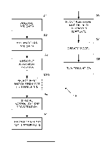
[0021] FIG. 1 is a flowchart of an embodiment that performs
electrotherapeutic
treatment by creating a realistic head model of a patient using a deformable
template.
[0022] FIG. 2 depicts an original MRI image obtained from a patient with
an
abnormality (e.g., a tumor).
[0023] FIG. 3 depicts the MRI image of FIG. 2 with the abnormality masked
out.
[0024] FIG. 4 depicts the normalization/registration process that
generates the
mapping and inverse mapping between FIG. 3 and a model deformable template of
a healthy
individual.
[0025] FIG. 5 depicts how the deformable template of FIG. 4 is deformed
to match
the shape of the patient's MRI image.
[0026] FIG. 6 depicts implanting the abnormality back into the deformed
model.
[0027] FIG. 7 depicts a system for electrotherapeutic treatment according
to one
embodiment.
7
[0028] FIG. 8 is another flowchart of an embodiment that performs
electrotherapeutic
treatment by creating a realistic head model of a patient using a deformable
template.
DETAILED DESCRIPTION OF THE PREFERRED EMBODIMENTS
[0029] The embodiments described herein generate a customized realistic
head model
for each individual patient by applying a non-rigid deformation to a
preexisting realistic head
model template, thus reducing the time and human labor required to create the
head model.
After the customized head model is generated for each individual patient,
conventional
simulation approaches are used to determine the optimal position for the
transducer on the
patient's body. Optionally, the pre-existing realistic head model template for
the healthy
patient may include tissue probability maps (TPMs). TPMs provide a model in
which each
point is represented by respective probabilities of that point belonging to
various tissue types
such as white matter, grey matter, C SF, etc.
[0030] Optionally, the patient images may be supplemented with other MRI
data such
as Diffusion Tensor Imaging (DTI) data or Water Content Electric Impedance
Tomography
(Wept) data to obtain more accurate representations of the conductivity in the
patient's head,
for example, as disclosed by E. Michel, D. Hernandez, and S. Y. Lee,
"Electrical conductivity
and permittivity maps of brain tissues derived from water content based on T 1
-weighted
acquisition," Magnetic Resonance in Medicine, 2016. MRI imaging techniques
such as DTI
or Wept are known to provide information on tissue conductivity as disclosed,
for example,
in US Application No. 15/336,660.
[0031] The FIG. 1 and FIG. 8 embodiments describes work-flows for creating
an
individualized realistic head model for each patient with reduced user
intervention, and using
these head models to optimize Tumor Treating Fields (T ields) array layouts
on patients.
Once a realistic model has been constructed for any given patient, the
optimization can be
performed in a fully automatic or semi-automatic manner using a sequence of
algorithms that
is also described herein. Although these workflows are described in the
context of TTFields
they may also be used in alternative contexts.
[0032] The FIG. 1 and FIG. 8 embodiments begin with a deformable template
that is
a realistic head model of a healthy individual (as opposed to a realistic head
model of the
actual patient). This head model may be obtained using any conventional
approach. For
example, the realistic head model may be created in a standard coordinate
system such as
8
Date Recue/Date Received 2022-12-01
Montreal Neurological Institute (MNI) or Talairach spaces. For example, Holmes
et. al.,
Journal of Computer Assisted Tomography, 22 324-333 (1998),
teaches mapping and averaging of MRI images in the standard space of MN!. If
the model does not exist in a desired standard coordinate space, the
transformation from a
standard coordinate space to the head model is preferably known and can be
used to map the
model to the standard coordinate space. One example of a realistic head model
built in a
standard coordinate space is the model based on the COLIN27 dataset (as
described in
Holmes et. al., Journal of Computer Assisted Tomography, 22 324-333 (1998))
created by
Miranda et. al. (as described in Miranda et. al., Physics in Medicine and
Biology, 59, 4137-
4147 (2014)). But a wide variety of alternative
realistic head models for the healthy individual may be used in place of the
Miranda model. It
is desirable that the MRIs from which the model was created are also available
for purposes
that will be described hereinafter.
[0033] In some embodiments, the realistic head model template of the
healthy
individual provides TPMs of tissue types. That is, each point in the model is
represented by
respective probabilities of that point belonging to various tissue types such
as white matter,
grey matter, CSF, etc. In some embodiments, the realistic head model template
of the healthy
individual provides one TPM per tissue type (e.g., 6 TPMs for 6 tissue types
of white matter,
grey matter, skull, scalp, CSF, and air).
[0034] FIG. 1 describes a process 100 for using the realistic head model of
the
healthy individual to create a realistic head model for any given patient by
using the existing
head model as a deformable template.
[0035] The process 100 begins in step Si, which is the acquisition of an
appropriate
set of MRI images. In step Si an MRI data set for an individual patient is
acquired using any
conventional approach. This data set preferably includes Mills carrying
structural data (such
as that obtained from Ti or T2 MRI sequences). Optionally, additional
sequences may also
be acquired such as DTI or perfusion imaging that may carry additional
information that
could be useful for model creation as will be described hereinafter. In some
instances, the
parameters of the MRI sequences are optimized to increase contrast between
specific tissue
types. Enhancing contrast is useful for the image segmentation that follows in
the steps
described below, for example, as in the sequence described in Windhoff et.
al., Human Brain
Mapping, 34 923-935 (2013) .
9
Date Recue/Date Received 2022-12-01
[0036] Preferably, the MRIs are acquired at the highest resolution that
is practically
possible. Usually, resolution of better than 1 mm x 1 mm x 1 mm is desired.
However,
images with lower resolution can also be used.
[0037] Optionally, DTI or Diffusion-weighted magnetic resonance imaging
(DWI)
data are acquired as well. This data can be used to map the conductivity (or
conductivity
tensor) within each voxel as described in Wenger et. al., International
Journal of Radiation
Oncology = Biology = Physics, 941137-43 (2016), and Basser et. al.,
Biophysical Journal, 66
259-267 (1994) . In alternative embodiments,
different imaging modalities may be used in place of MRI images, such as CT
images, a
combination of MRI and CT images, etc.
[0038] Process 100 continues in Step S2, which is image pre-processing.
However, in
some cases, no pre-processing is needed and Step S2 may be skipped. In step
S2, image pre-
processing is performed on the data obtained in step Si to obtain a cleaner
image. FIG. 2
shows an example of an MRI image 200 resulted after performing image pre-
processing in
step S2. The pre-processing may be implemented using any conventional
approach. In some
embodiments, the image pre-processing step includes image alignment and
distortion
correction. For example, image alignment may be implemented to remove
artifacts due to
motion from the images using any conventional approach. Re-alignment may be
performed
using affine registration, using any suitable conventional approach such as
Statistical
Parametric Mapping (SPM) as implemented in SPM 8.0 toolbox that is developed
for the
construction and assessment of spatially extended statistical processes used
to test hypotheses
about functional imaging data. In addition, distortion to the images (e.g.,
caused by induced
eddy currents) may be corrected at this stage. Realignment of images is
required when more
than one dataset is used to create the models, in which case those multiple
datasets need to be
aligned. For example, when axial and coronal image sets are used for super
resolution, they
need to be aligned. As another example, when DTI data is used in addition to
Ti data, DTI
data and Ti data may need to be aligned.
[0039] In some embodiments, an additional pre-processing step of
manipulating the
header of the MRI image is performed (e.g., in Neuroimaging Informatics
Technology
Initiative (NiffI) format), so that the origin of the file matches the origin
of the template
TPM. The origin of the file refers to the origin of axes in the file. This
step helps facilitate
registration of the MRI image into the deformable space as described in step
S4 below. In
Date Recue/Date Received 2022-12-01
CA 03047067 2019-06-13
WO 2018/109691 PCT/1B2017/057901
some embodiments, the origin of axes in the patient MRI images and in the
files associated
with the deformable template are positioned at similar voxels to help
facilitate execution of
step S4.
[0040] Optionally, super-resolution algorithms that combine several MRI
datasets of
a single patient into a single image may be used. These algorithms are useful
for creating a
dataset that shows the full head of the patient, when all other datasets
truncate the head at
different points, or for creating an image with high-resolution (or slice
spacing) when the
original data is of lower resolution. High-resolution datasets, and datasets
that show the full
3D head are useful for creating an accurate head model. One example of a super-
resolution
algorithm is described in Woo, et al. "Reconstruction of high-resolution
tongue volumes from
MRI." IEEE Transactions on Biomedical Engineering, 59.12 (2012). This
algorithm
employed a number of pre-processing steps including motion correction and
intensity
normalization, followed by a region-based maximum a posteriori (MAP) Markov
random
field (MRF) approach to combine three orthogonal image volumes of MRI datasets
into a
single super-resolution isotropic volume reconstruction of the tongue. The
output super-
resolution image was superior to the input images in terms of both signal-to-
noise ratio
(SNR) and resolution.
[0041] In many cases, background noise and aliasing may be present and
may
deteriorate the quality of the head model created using deformable templates.
In particular,
when background noise is present, the contour of the skull obtained during
model creation is
often inaccurate and includes part of the background. Accordingly, some
embodiments may
implement various thresholding schemes known to persons skilled in the
relevant arts to
remove background noise and aliasing. Aliasing as referred herein relates to
an artifact in
MRI images that results in a weak "shadow" of the subject being imaged to
appear in the
background (i.e., the shadow is caused by aliasing). The shadow is typically
upside down and
directly attached to the main image. In this case, a thresholding scheme may
be used to
remove the weak shadow in the background. One example of a thresholding scheme
that may
be used to enhance image quality is a semi-automatic method in which the user
selects a
single value representing the background noise and the software applies this
value as a
threshold to automatically detect the contour of the scalp and zero the
intensity of the
background noise slice by slice. A wide variety of alternative approaches may
also be used,
as will be appreciated by persons skilled in the relevant arts.
11
[0042] Alternatively or additionally, scanner-specific pre-processing may
be applied.
For example, images may be converted from Digital Imaging and Communications
in
Medicine (DICOM) format to NifTI.
[0043] Process 100 continues in Step S3, which is masking of abnormal
regions in the
head. Step S3 is implemented only if a tumor or other abnormality (e.g., skull
defects/flaps)
exists in the patient MRI images. In step S3, these abnormal regions are
masked out as
depicted in image 300 in FIG. 3. Optionally, the regions that are masked may
extend beyond
the tumor/abnormality if necessary so as to include all regions in which the
normal structure
of the brain has been significantly disturbed due to the presence of the tumor
or other defects.
[0044] One way to accomplish this masking step is to use supervised
segmentation to
properly mark the abnormal head regions. During this step of the supervised
segmentation,
multiple types of abnormalities are labeled in order to reach the desired
detail level of the
final model as will be described hereinafter. The supervised segmentation may
be performed
in a semi-automatic manner using, for example, tools such as ITK-SNAP (see,
e.g.,
Yushkevich et. al, Neuroimage, 31 1116-1128 (2006) .
[0045] Alternatively, masking can be performed using automatic segmentation
algorithms. For instance, Porz, et al. "Multi-modal glioblastoma segmentation:
man versus
machine." Public Library of Science (PLOS) One, 9.5 (2014), teach a method for
automatic
segmentation of pre-operation MRI images. In some situations, manual
corrections to the
results of the automatic segmentation process may be required to ensure
accurate masking of
the tumor.
[0046] In some embodiments, the regions that are masked are determined
manually.
One way to accomplish this is to present the MRI data to a user, and ask the
user to outline
the tumor on the data. The data presented to the user may include structural
MRI data (e.g.,
Ti, T2 data). The different MRI modalities may be registered onto each other,
and the user
may be presented with the option to view any of the datasets and outline the
tumor. The user
may be asked to outline the tumor on a 3D volumetric representation of the MRI
data, or the
user may be given the option of viewing individual 2D slices of the data and
marking the
tumor boundary on each slice. Once the boundaries have been marked on each
slice, the
tumor within the anatomic volume can be found. In this case, the volume marked
by the user
12
Date Recue/Date Received 2022-12-01
CA 03047067 2019-06-13
WO 2018/109691 PCT/1B2017/057901
would correspond to the tumor. In some situations, margins of a predefined
width (e.g., 20
mm) are added to the tumor, and the resulting volume is used as the region-to-
be-masked.
[0047] Note that when no tumor or other abnormality exists in the
patient's MRI
images (e.g., when the patient is healthy), step S3 is omitted.
[0048] For certain patients, the results of the segmentation will reveal
that the tumor
is not homogeneous, in which case the tumor may also be segmented into several
sub-regions
so that such segmentation information can be used for more accurately planting
the tumor
back into the realistic head model after the deformation step as will be
described in further
detail herein. Examples of such sub-regions are active/enhancing tumor,
necrotic regions,
resection cavity, etc. Conventional automated segmentation algorithms may be
used for
detailed GBM segmentation. An example of a publicly available algorithm is the
recent
Brain Tumor Image Analysis (BraTumIA) software which distinguishes necrotic
core,
edema, non-enhancing tumor, and enhancing tumor while needing four different
imaging
modalities (T1, T 1-contrast, T2-contrast, and FLAIR). Techniques which only
need a T1 as
input also exist. But regardless of any variations within the tumor, all
regions of the tumor
are masked out of the original patient image. In case skull defects are in the
image, then
these regions are segmented and masked out as well.
[0049] Note that while a variety of approaches for identifying the
abnormal region in
the image are described above, a wide variety of alternative approaches will
be apparent to
persons skilled in the relevant arts.
[0050] Process 100 continues in step S4, which is Spatial
Normalization/Registration.
In step S4, a mapping that warps the current set of MRI images for a given
patient into the
standard space of the template model is identified. FIG. 4 depicts the
normalization/registration process 400 that generates the mapping and inverse
mapping
between a patient MRI image 402 (with a masked-out abnormality) and the
deformable
model template 404 of a healthy individual. The inverse of this mapping is
also identified (for
use in step S5 below to map from the standard space to the space of the
patient MRI set).
[0051] For example, one approach for generating this mapping is to
register the
patient MRI images to a standard coordinate space, such as the MINI space or
the Talairach
space. Image registration refers to spatial transformation of an image so that
certain features
of the image align with corresponding features in another image/space. This
can be done by
13
any known methods that will be apparent to persons skilled in the relevant
arts, for example,
by using readily available software packages including but not limited to FSL
FLIRT, and
SPM.
[0052] =Notably, abnormal regions masked out in step S3 are omitted from
the
registration process. Ignoring the masked out regions during registration
ensures that the
registration is performed using only healthy regions of the head, which can be
effectively
mapped to the model TPMs that describe the probability that a specific voxel
in the standard
space belongs to a specific tissue type. Advantageously, omitting the abnormal
regions
improves the robustness of the registration process. In some embodiments, the
TPMs are
constructed in the model template space.
[0053] Alternatively, non-rigid registration algorithms (as described, for
example, in
Zhuang et. al, IEEE Transactions on Medical Imaging, 30 0278-0062 (2011))
teaches an algorithm for image registration using mutual
information) can be used to register the patient MRI images to either a
standard coordinate
space (e.g., a realistic model template of a healthy individual) or to a
voxelized version of the
corresponding segmented model template. Note that a variety of algorithms for
mapping
patient MM images into a standard space are well known to persons skilled in
the relevant
arts. Moving in the opposite direction (i.e., from the standard space to the
patient MRI
images, as described below) will use the inverse of those same mappings.
[0054] The mappings described above are found for the points in the patient
head that
fall outside of the masked-out areas. The transformations in the region(s)
that were masked
out prior to registration can be estimated, for example, by interpolating the
deformation map
found in the rest of the head into these regions, or using any of a variety of
alternative
approaches that will be apparent to persons skilled in the relevant arts. In
some embodiments,
it may not be necessary to find a transformation for the region(s) that were
masked-out prior
to registration. This is due to the fact that the areas of the deformable
model template that
correspond to the masked-out region contain information related to some
"natural" structure
(e.g., healthy tissue). Therefore, after the mappings described above are
applied to the
deformable model template for the points that fall outside of the masked-out
regions, the
deformed model template already includes some model data in these regions
since the
"natural" structure is maintained in these regions. For example, if a sphere
is masked-out
from the left hemisphere in patient images and the mappings are applied to the
deformable
14
Date Recue/Date Received 2022-12-01
CA 03047067 2019-06-13
WO 2018/109691 PCT/1B2017/057901
model template only for the points that fall outside of the sphere, the
contents of the sphere in
the left hemisphere of the deformed model template will resemble some natural
structure.
[0055] In some embodiments, model TPMs are used to find the mapping from
the
standard space to the patient space. In some embodiments, the model TPMs may
be derived
from the MRI dataset from which the deformable template was derived. Using
TPMs derived
from this MRI dataset may lead to a more accurate representation of the
patient in the final
model, than when using other TPMs. The reason for this is as follows. TPMs
describe the
probability of a voxel in a standard space belonging to each tissue type.
Generally, TPMs are
derived from multiple MRIs of different subjects. Thus, TPMs represent the
probability of a
voxel belonging to each tissue type throughout a population of individuals.
This implies that
when performing registration using TPMs derived from multiple individuals, the
output
mapping represents a mapping into some representative space that by definition
smooths out
anatomical variation between the individuals from which the TPMs were derived.
However,
when creating patient models by deforming a head model of a healthy
individual, it may be
desirable that the mapping calculated when registering the patient MRI onto
the TPMs
captures the anatomical features of the healthy head model with as much
accuracy as
possible. This accuracy ensures that when the deformable template is later
deformed into the
patient space in step S5 below, the resulting model resembles the patient with
as much
accuracy as possible. Hence, it is desirable that the TPMs onto which the
registration in step
S4 is performed represent the individual from which the healthy head model was
derived, as
opposed to a population of individuals from which TPMs are typically derived.
[0056] One approach for creating TPMs that represent the healthy
individual from
which the deformable model template was derived is to simultaneously register
and segment
MRI images of the healthy individual using an existing set of generic TPMs
(e.g., TPMs built
in a standard space using data of multiple individuals). An example of an
algorithm that
accomplishes this is the unified segmentation algorithm by Ashburner and
Friston ("Unified
segmentation." Neuroimage 26.3 2005) which is implemented in SPM 8.0 toolbox
described
above. Outputs from this process include probability maps describing the
probability that a
voxel (of the MRI images registered to the standard space) belongs to a
specific tissue type.
The number of probability maps generated in this process is equal to the
number of tissue
types in the model (typically 6), and each voxel in a map is assigned a value
from 0 to 1
which indicates the probability that the voxel belongs to a specific tissue
type. By definition,
CA 03047067 2019-06-13
WO 2018/109691 PCT/1B2017/057901
these probability maps are TPMs that represent the healthy individual from
whom the healthy
head model (deformable template) was derived.
[0057] In some cases, manual corrections are made to the TPMs to obtain a
better
representation of the deformable template. For instance, the probability maps
of the skull and
scalp could be modified to enhance the boundaries of the skull or scalp. This
may be done,
for example, by manually assigning probability values to specific voxels such
that the
probability of that voxel to belong to one tissue types is close to 1, and the
probability of it
belonging to other tissue types is close to 0. A final step in creating TPMs
from these
probability maps is to apply a smoothing filter to the individual maps.
Smoothing is
important to allow adjustments to an MRI of any individual. The smoothing can
be
performed for instance using a Gaussian filter with a smoothing kernel of 4 mm
x 4 mm x 4
mm FWHM (Full width half maximum).
[0058] Process 100 continues in Step S5, which is Deforming/Warping the
template
into the desired space. In step S5, the inverse mapping found in step S4 is
applied to the
deformable model template to map the deformable model template into the
coordinate system
of the patient MRI images. FIG. 5 depicts the deforming/warping process 500
that applies the
inverse mapping to a deformable model template 502 to obtain the warped model
504. In
some embodiments, the inverse mapping applies a three-dimensional
transformation to the
deformable model template 502, thereby warping the deformable model template
502 to
conform to patient-specific anatomical attributes.
[0059] It should be noted that prior to warping, the model template 502
is a model of
a healthy reference individual's brain; and after warping, the warped model
504 will
represent an approximation of what the patient's brain would look like if it
were healthy. In
other words, this step results in a model of a healthy individual that has
been warped to fit
into the head shown in the patient MRI images, but lacks a tumor. Notably,
despite the fact
that this warped model originates from a model template (instead of from each
individual
patient's head), it is still useful for analyzing the electrical fields that
can be induced inside
each individual patient's head.
[0060] The deformation in step S5 can be applied to a voxelized version
of the model
or to a meshed version of the model. In the voxelized version, each voxel
indicates a tissue
type (or tissue type probabilities) at the location of the coordinates of that
voxel. In the
16
CA 03047067 2019-06-13
WO 2018/109691 PCT/1B2017/057901
meshed version, each mesh defines a boundary between different tissue types,
and the
deformation is applied to these meshes in the deformable model template. In
some
embodiments, a binary image of each tissue type is created, and each resulting
binary image
is deformed separately.
[0061] Optionally, any holes that may appear in the deformed image of a
tissue type
may be assigned to one of the tissue types that appear in that image. An
example of a
procedure designed to assign tissue types to holes that appear between binary
masks can be
found in Timmons, et al. "End-to-end workflow for finite element analysis of
tumor treating
fields in glioblastomas," Physics in Medicine & Biology, 62.21 (2017), where
using the
software ScanIP, a Gaussian filter function smooths the boundaries between
masks to avoid
convergence issues. Cavities in the mask are filled, and islands above a
threshold (which may
vary with tissue type) are removed. The current mask is duplicated and then
dilated (by one
to three voxels, depending on the tissue mask) and Boolean added to the next
mask on all
slices. Any of a variety of alternative approaches for filling holes that
appear in the deformed
image may also be used.
[0062] After the formation of the images for each individual tissue type,
all the binary
images are combined into a single image representing a segmented image of the
deformed
head model.
[0063] In cases where a voxel in the combined model is assigned to more
than one
tissue type, a heuristic logic may be used to determine the tissue type in the
final image. For
instance, the logic may state that all voxels where grey and white matter
overlap in the
combined model are assigned to white matter only, or vice versa.
[0064] In embodiments where the model template includes TPMs (i.e., each
tissue in
the model template is represented by a 3D matrix describing the probability
that each voxel
belongs to a specific tissue type), the TPMs are deformed, and the deformed
TPMs are
combined into a final model such that each voxel in the combined model is
assigned a tissue
type based on some heuristic logic. For instance, each voxel is assigned to
the tissue type
which has the highest probability of occupying that voxel.
[0065] In some embodiments, the probability assigned by different TPMs to
each
voxel is used to determine the combination of the conductivity properties in
the created
voxelized model. In other words, it is assumed that the voxel does not
necessarily contain a
17
certain tissue type, and the final conductivity is assigned to the voxel as a
weighted sum of
the conductivities of all tissue types, with the weights derived from the
probability values
assigned to each tissue type in that voxel.
[0066] In some embodiments, conductivity values are assigned to the tissue
maps by
additionally incorporating information obtained from MRI imaging techniques
such as DTI
or Wept, which are known to provide information on tissue conductivity as
disclosed, for
example, in US Application No. 15/336,660 (published as US2017/0120041) .
This information could be incorporated into
the model, for instance, by assigning conductivity to each voxel based on the
weighted
average of the model-derived conductivity and the Wept/DTI derived
conductivity.
[0067] Process 100 continues in Step S6, which is planting the abnormality
back into
the deformed template. In step S6, the deformed template is edited so that
each voxel of the
template that corresponds to the masked region found in step S3 is assigned to
an abnormal
tissue type (e.g., the tumor or surrounding region). FIG. 6 depicts this
process 600 where an
abnormality identified in the patient image 602 is implanted in a deformed
model template
604. In some embodiments, the planting is performed by assigning tissue types
in each of the
abnormal regions according to the segmentation performed in step S3. More
specifically, the
tissue type assigned to each point in the abnormal region after deformation is
based on the
tissue type identified for a corresponding point in the segmentation in step
S3 before
deformation. Accordingly, if the segmentation in step S3 identifies more than
one tissue type
in the abnormal region, then there may be more than one tissue type assigned
to the abnormal
region after deformation. In alternative embodiments, the planting may be
performed by
assigning a default abnormal tissue type to the abnormal region after
deformation. In other
alternative embodiments, the planting may be performed by having a user
manually assign a
tissue type to the points in the abnormal region.
[0068] Process 100 continues in Step S7, which is model creation. In the
modeling
step (S7), electrical properties such as conductivity and permittivity are
assigned to the
various tissue types. Note that the tissue types are ordinarily obtained from
the deformed
template. However, a tissue type corresponding to tumor tissue will be
assigned to each voxel
that corresponds to the implanted abnormality. Models of electrodes (or
transducer arrays)
are placed on the model skin, and suitable boundary conditions are applied. In
some
embodiments, the modeling step S7 assumes that each tissue type is homogeneous
and
18
Date Recue/Date Received 2022-12-01
CA 03047067 2019-06-13
WO 2018/109691 PCT/1B2017/057901
therefore a single value for the electrical property is assigned to each
tissue type (as
described, for example, in Miranda et. at., Physics in Medicine and Biology,
59, 4137-4147
(2014), Wenger et. al., Physics in Medicine and Biology, 60 7339-7357 (2015),
and Wenger
et. al., International Journal of Radiation Oncology = Biology = Physics,
941137-43 (2016)).
In other models, the conductivity in each voxel is assigned from DTI or DWI
images
acquired during the image acquisition step. DTI assigns anisotropic electric
properties (a 3x3
tensor) to each voxel, whereas DWI assigns isotropic conductivity (a scalar)
to each voxel.
Finally, the model is divided into volume elements, for example, by voxelizing
or
alternatively by volume meshing.
[0069] Process 100 continues in Step S8, After the head model is created
and the
model electrodes have been added to the head model, a simulation is run in
step S8. This
simulation finds an optimal electrode array layout by solving for the
corresponding induced
electric field using an appropriate numerical technique including but not
limited to finite
elements methods or finite differences methods.
[0070] Optimization of electrode array layouts means finding the array
layout that
optimizes the electric field within the diseased regions of the patient's
brain (tumor). This
optimization may be implemented over the volume targeted for treatment (target
volume)
within the realistic head model by automatically placing transducer arrays and
setting
boundary conditions on the realistic head model; calculating the electric
field that develops
within the realistic head model once arrays have been placed on the realistic
head model and
boundary conditions applied; and running an optimization algorithm to find the
layout that
yields optimal electric field distributions within the target volume. Although
a variety of
alternative approaches may be used, one example for implementing these four
steps is
provided below.
[0071] The position and orientation of the arrays on the realistic head
model may be
automatically calculated for a given iteration. Each transducer array used for
the delivery of
TTFields in the OptuneTM device comprises a set of ceramic disk electrodes,
which are
coupled to the patient's head through a layer of medical gel. When placing
arrays on real
patients, the disks naturally align parallel to the skin, and good electrical
contact between the
arrays and the skin occurs because the medical gel deforms to match the body's
contours.
However, virtual models are made of rigidly defined geometries. Therefore,
placing the
arrays on the model requires an accurate method for finding the orientation
and contour of the
19
CA 03047067 2019-06-13
WO 2018/109691 PCT/1B2017/057901
model surface at the positions where the arrays are to be placed, as well as
finding the
thickness/geometry of the gel that is necessary to ensure good contact of the
model arrays
with the realistic patient model. In order to enable fully automated
optimization of field
distributions these calculations have to be performed automatically.
100721 A variety of algorithms to perform this task may be used. The
steps of one
such algorithm devised for this purpose are set forth below.
a. Define the position at which the central point of the transducer array
will be placed on
the model head. The position could be defined by a user or as one of the steps
in the
field optimization algorithm.
b. Using the input from step (a) in conjunction with knowledge about the
geometry of
the disks and how the disks are arranged in the array, calculate the
approximate
positions of the centers of all disks in the transducer array within the
model.
c. Calculate the orientations of the surface of the realistic model at the
positions where
the disks are to be placed. The calculation is performed by finding all points
on the
computational phantom skin that are within a distance of one disk radius from
the
designated center of the disk. The coordinates of these points are arranged
into the
columns of a matrix, and singular value decomposition performed on the matrix.
The
normal to the model skin is then the eigenvector that corresponds to the
smallest
eigenvalue found.
d. For each disk in the transducer array: calculate the thickness of the
medical gel that is
required to ensure good contact between the disks and the patient's body. This
is done
by finding the parameters for a cylinder with its height oriented parallel to
the skin
surface normal. The cylinder is defined with a radius equal to the radius of
the disks,
and its height set to extend a pre-determined amount (this is a pre-determined
constant) beyond the points on the skin used to find the normal. This results
in a
cylinder that extends at-least the pre-determined amount out from the phantom
surface.
e. On the model, create the cylinders described in (d).
f. Through binary logical operations (e.g., subtract head from cylinder)
remove from the
model the regions of the cylinder that protrude into the realistic model of
the patient.
The resulting "truncated cylinders" represent the medical gel associated with
the
transducer arrays.
CA 03047067 2019-06-13
WO 2018/109691
PCT/1B2017/057901
g. On
the outer side of the "truncated cylinders" place disks that represent the
ceramic
disks of the transducer arrays.
[0073] Then, the electric field distribution is calculated within the
head model for the
given iteration. Once the head phantom is constructed and the transducer
arrays (i.e., the
electrode arrays) that will be used to apply the fields are placed on the
realistic head model,
then a volume mesh, suitable for finite element method analysis, can be
created. Next,
boundary conditions can be applied to the model. Examples of boundary
conditions that
might be used include Dirichlet boundary (constant voltage) conditions on the
transducer
arrays, Neumann boundary conditions on the transducer arrays (constant
current), or floating
potential boundary condition that set the potential at that boundary so that
the integral of the
normal component of the current density is equal to a specified amplitude. The
model can
then be solved with a suitable finite element solver (e.g., a low frequency
quasi-static
electromagnetic solver) or alternatively with finite difference algorithms.
The meshing,
imposing of boundary conditions, and solving of the model can be performed
with existing
software packages such as Sim4Life, Comsol Multiphysics, Ansys, or Matlab.
Alternatively,
custom computer code that realizes the finite element (or finite difference)
algorithms could
be written. This code could utilize existing software resources such as C-Gal
(for creating
meshes), or FREEFEM++ (software written in C++ for rapid testing and finite
element
simulations). The final solution of the model will be a dataset that describes
the electric field
distribution or related quantities such as electric potential within the
computational phantom
for the given iteration. In some embodiments, the model is voxel-based (i.e.,
it comprises
box-shaped volume elements). In these embodiments, Finite Differences Time
Domain
(FDTD) algorithms may be used to solve the model, for example, using the quasi-
electrostatic solver associated with the "Sim4Life" software package from ZMT
Zurich
MedTech AG.
[0074] Then, an optimization algorithm is used to find the array layout
that optimizes
the electric field delivery to the diseased regions of the patient's brain
(tumor) for both
application directions (LR and AP). The optimization algorithm will utilize
the method for
automatic array placement and the method for solving the electric field within
the head model
in a well-defined sequence in order to find the optimal array layout. The
optimal layout will
be the layout that maximizes or minimizes some target function of the electric
field in the
diseased regions of the brain, considering both directions at which the
electric field is applied.
This target function may be for instance the maximum intensity within the
diseased region or
21
CA 03047067 2019-06-13
WO 2018/109691 PCT/1B2017/057901
the average intensity within the diseased region. It also possible to define
other target
functions.
[0075] There are a number of approaches that could be used to find the
optimal array
layouts for patients, three of which are described below. One optimization
approach is an
exhaustive search. In this approach the optimizer will include a bank with a
finite number of
array layouts that should be tested. The optimizer performs simulations of all
array layouts in
the bank and picks the array layouts that yield the optimal field intensities
in the tumor (the
optimal layout is the layout in the bank that yields the highest (or lowest)
value for the
optimization target function, e.g., the electric field strength delivered to
the tumor).
[0076] Another optimization approach is an iterative search. This
approach covers the
use of algorithm such as minimum-descent optimization methods and simplex
search
optimization. Using this approach, the algorithm iteratively tests different
array layouts on the
head and calculates the target function for electric field in the tumor for
each layout. At each
iteration, the algorithm automatically picks the configuration to test based
on the results of
the previous iteration. The algorithm is designed to converge so that it
maximizes (or
minimizes) the defined target function for the field in the tumor.
[0077] Yet another optimization approach is based on placing a dipole at
the center of
the tumor in the model. This approach differs from the other two approaches,
as it does not
rely on solving field intensity for different array layouts. Rather, the
optimal position for the
arrays is found by placing a dipole aligned with the direction of the expected
field at the
center of the tumor in the model, and solving the electromagnetic potential.
The regions on
the scalp where the electric potential (or possibly electric field) is maximal
will be the
positions where the arrays are placed. The logic of this method is that the
dipole will generate
an electric field that is maximal at the tumor center. By reciprocity, if we
were able to
generate the field/voltage on the scalp that the calculation yielded, then we
would expect to
obtain a field distribution that is maximal at the tumor center (where the
dipole was placed).
The closest we can practically get to this with our current system is to place
the arrays in the
regions where the potential induced by the dipole on the scalp is maximal.
[0078] Note that alternative optimization schemes can be used to find an
array layout
that optimizes the electric field within diseased regions of the brain. For
example, algorithms
that combine the various approaches mentioned above. As an example of how
these
22
approaches may be combined, consider an algorithm in combining the third
approach
discussed above (i.e., positioning the dipole at the center of the tumor in
the model) with the
second approach (i.e., the iterative search). With this combination, an array
layout is initially
found using the dipole at the center of the tumor approach. This array layout
is used as input
to an iterative search that finds the optimal layout.
100791 Once the layout that optimizes the electric field within the
diseased regions of
the patient's brain has been determined (e.g., using any of the approaches
explained herein, or
an appropriate alternative approach), the electrodes are positioned in the
determined
positions. AC voltages are then applied to the electrodes (e.g., as described
in US Patent
7,565,205) to treat the disease.
100801 FIG. 7 depicts an example system 700 for electrotherapeutic
treatment that
may be used after the positions of the electrodes have been optimized as
described herein.
System 700 includes a controller 702 that applies TTFfields to a patient by
applying voltages
to capacitively coupled transducer arrays 42, 44 that are affixed to the
patient's scalp 40 at
the determined positions. Note that the front view of the scalp 40 is depicted
in FIG. 7 and
only three of the four patches of electrodes are visible in the figure and
that neither the eyes
nor the ears are represented.
[0081] Optionally, the system can be designed to work with multiple model
templates. In this case, an additional step S3.5 is implemented subsequent to
step S3 and prior
to step S4. In step S3.5, the resemblance of the patient MRI images to each of
a plurality of
templates is first measured (using, for example, a measure of correlation or
mutual
information). The deformable template that most closely resembles the patient
MRI images is
selected and used in all subsequent steps. Alternatively, in some embodiments,
selection of
the deformable template that most closely resembles the patient MRI images may
be
performed after registering patient images to a standard space at step S4 and
prior to step S5.
In these embodiments, the deformable template that most closely resembles the
patient MRI
images is used in all steps subsequent to S4.
[0082] Optionally, the system may be configured as a learning system in
which each
realistic head model that is created using the process described above serves
as a deformable
template for future models. Both the deformed healthy model created in step S5
and the
resulting model that includes defects (created in step S6) could be added to
the database. If a
23
Date Recue/Date Received 2022-12-01
CA 03047067 2019-06-13
WO 2018/109691 PCT/1B2017/057901
patient's MRI images in the original image stack resemble a stored template of
a brain with a
tumor to a close enough degree, then it is possible to create a model
representing the patient
MRI images by measuring deformations on the previously stored template.
[0083] Finally, while the concepts set forth herein are discussed in the
context of an
MRI image of a patient's head, the same principles may be applied to other
portions of a
patient's body and/or imaging modalities other than MRI.
[0084] FIG. 8 is a flowchart 800 of a method for optimizing the position
of electrodes
that will subsequently be used to perform electrotherapeutic treatment by
creating a realistic
head model of a patient using a deformable template. The electrotherapeutic
treatment may
be TDCS, TMS, or TTFields.
[0085] At S10 one or more 3D images of a body area of a patient are
received. The
3D images may be MRI images, CT images, or images in any other modalities
known in the
art. The body area may be the patient's head, or any other body area.
Optionally, the images
may be pre-processed using any of the approaches described herein (for
example, as
described herein with reference to step S2 of FIG. 1).
[0086] At S20 portions of the image that correspond to abnormal tissue
are identified.
For example, when the body area is the head of a patient, such portions may
correspond to a
tumor or a skull abnormality. The abnormality may be identified manually,
automatically, or
semi-automatically, according to any of the methods described herein or
according to any
other appropriate methods that will be apparent to persons skilled in the
relevant arts. In some
embodiments, the portions of the image that correspond to the abnormal tissue
are identified
by segmentation of the image.
[0087] At S30 a data set is generated to correspond to the image with the
abnormal
tissue masked out. This may be accomplished, for example, by masking out the
abnormal
tissue includes ignoring the abnormal regions in the registration process
described in S50
below. In some embodiments, masking out the abnormal region is implemented by
flagging
data points in this region and excluding all flagged data points during the
registration process
described in S50 below.
[0088] At S40 a model template that specifies positions of a plurality of
tissue types
in a healthy version of the body area of the patient is retrieved. For
example, when the body
24
CA 03047067 2019-06-13
WO 2018/109691 PCT/1B2017/057901
area is the head of a patient and the abnormal tissue corresponds to a tumor
in the head of the
patient, the model template corresponds to the head of a healthy individual
and lacks any
tumors. In some embodiments, the model template may be selected from multiple
existing
model templates based on similarities between the image and each of the
multiple model
templates. For example, a measure of similarity such as mutual information or
a distance may
be determined between the patient data set (derived by masking out
abnormalities in the
patient image) and each one of several model templates, and the model template
that is most
similar to the patient data set (e.g., has the least distance or the most
mutual information) may
be selected accordingly. In some embodiments, the model template may include
TPMs, and
the TPMs may correspond to the same healthy individual from whom the model
template has
been derived (and derived from images of the healthy individual) or to
multiple individuals.
100891 At S50 the model template is deformed in space so that features in
the
deformed model template line up with corresponding features in the data set.
In some
embodiments, the model template is deformed by determining a mapping that maps
the data
set to a coordinate space of the model template; and applying an inverse of
the mapping to
the model template. In some embodiments, the mapping may be determined by
registering
the dataset to a coordinate space of the model template. That is, the mapping
warps the
dataset to the model template. Hence, the inverse of the mapping warps the
model template to
the data set and thereby provides a realistic model for the patient if the
patient had no
abnormalities. In some embodiments, the mapping from the data set to the model
template is
determined for points in the data set that fall outside of the masked-out
portion. In
embodiments where the model template includes TPMS, the mapping maps the data
set to the
TPMs, and the inverse of the mapping is applied to each one of the TPMs and
the inverse-
mapped TPMs are combined into a segmented image comprising the deformed model
template.
100901 At S60 portions of the deformed model template that correspond to
the
masked-out portion of the data set are modified so that the modified portions
represent the
abnormal tissue. The modification may be performed according to the
information obtained
during the identification of the abnormal portions in S20. For example, one or
more abnormal
tissue types identified in S20 may be assigned to corresponding portions in
the defol riled
model template. Alternatively, a pre-determined generic tissue type may be
assigned to the
masked-out portion.
CA 03047067 2019-06-13
WO 2018/109691
PCT/1B2017/057901
[0091] At S70 a model of electrical properties of tissues in the body
area is generated
based on (a) the positions of the plurality of tissue types in the deformed
and modified model
template and (b) the position of the abnormal tissue in the deformed and
modified model
template. The electrical properties may be electrical conductivity, electrical
resistivity, or any
other electrical property pertinent to electrotherapeutic treatment of the
body area. In some
embodiments, for example, a different electrical property value may be
assigned to each
tissue type according to a previously populated look-up table.
[0092] At S80 an electrode placement layout that maximizes field strength
in at least
a portion of the abnormal tissue is detel _______________________________
mined by using the model of electrical properties to
simulate electromagnetic field distributions in the body area caused by
simulated electrodes
placed at a plurality of different sets of candidate positions respective to
the body area, and
selecting one of the sets. In some embodiments, the electrode placement layout
is determined
by applying a boundary condition to the simulated electrodes in each one of at
least two
electrode placement layouts; solving a field distribution in the body area for
each one of the
at least two electrode placement layouts; and choosing the electrode placement
layout that
yields the strongest field within the abnormal region. The boundary condition
may
correspond, for example, to voltages applied to the simulated electrodes. In
some
embodiments, the field distribution is solved using a numerical technique such
as a finite
elements method or a finite differences method.
[0093] At S90 the determined electrode placement layout is output for
subsequent use
as a guide for placing electrodes respective to the body area of the patient
prior to use of the
electrodes for electrotherapeutic treatment (e.g. TTFields).
[0094] Models built in this manner could also be used for other
applications in which
calculating electric field and or electric current distributions within the
head may be useful.
These applications include, but are not limited to: direct and alternating
current trans-cranial
stimulation; simulations of implanted stimulatory electrode field maps;
planning placement of
implanted stimulatory electrodes; and source localization in
electroencephalogram (EEG).
[0095] Finally, although this application describes methods for
optimizing array
layouts on the head, the same steps may be used for optimizing array layouts
at other body
regions (including but not limited to the thorax or abdomen).
26
CA 03047067 2019-06-13
WO 2018/109691
PCT/1B2017/057901
[0096] While the present invention has been disclosed with reference to
certain
embodiments, numerous modifications, alterations, and changes to the described
embodiments are possible without departing from the sphere and scope of the
present
invention, as defined in the appended claims. Accordingly, it is intended that
the present
invention not be limited to the described embodiments, but that it has the
full scope defined
by the language of the following claims, and equivalents thereof.
27