Note: Descriptions are shown in the official language in which they were submitted.
85392276
SURFACE MODIFif.1) OVERHEAD CONDUCIOR
[001] This application is a divisional of Canadian Patent Application No.
2,880,495,
filed on April 19,2013.
FIELD OF THE INVENTION
[002] The present invention relates to a surface modified overhead
conductor with a
coating that allows the conductor to operate at lower temperatures.
BACKGROUND OF THE INVENTION
[0031 As the need for electricity continues to grow, the need for
higher capacity
transmission and distribution lines grows as well. The amount of power a
transmission line can
deliver is dependent on the current-carrying capacity (ampacity) of the line.
The ampacity of a
line is limited by the maximum safe operating temperature of the bare
conductor that carries the
current. Exceeding this temperature can result in damage to the conductor or
the accessories of
the line. Moreover, the conductor gets heated by Ohmic losses and solar heat
and it gets cooled
by conduction, convection and radiation. The amount of heat generated due to
Ohmic losses
depends on current (I) passing through it and its electrical resistance (R) by
the relationship
Ohmic lossel2R. Electrical resistance (R) itself is dependent on temperature.
Higher current
and temperature leads to higher electrical resistance, which, in turn, leads
to more electrical
losses in the conductor.
1
CA 3048274 2019-07-02
=
WO 2014/025420 PC1102013/037433
[004] Several solutions have been proposed in the att. WO 2007/034248 to
Simic
discloses overhead conductors coated with a spectrally selective surface
coating. The coating
has a coefficient of heat emission (E) higher than 0.7 and coefficient of
solar absorption (A) that
is less than 0.3. Sunk also requires that the surface be white in color to
have low solar
absorption.
[005] DE 3824608 discloses an overhead cable having a black paint coating
with an
emissivity greater than 0.6, preferably greater than 0.9. The paint is made of
a plastic (e.g.
polyurethane) and black color pigment.
[006] FR 2971617 discloses an electric conductor coated with a polymeric
layer whose
emissivity coefficient is 0.7 or more and solar absorption coefficient is 0.3
or less. The polymeric
layer is produced from polyvinylidene fluoride (PVDF) and a white pigment
additive.
[007] Both FR 2971617 and WO 2007/034248 require white coatings that are
not
desirable due to glare and discoloration over time. Both DE 3824608 and FR
2971617 require
polymeric coatings that are not desirable due to their questionable heat and
wet aging
characteristics.
[008] Therefore, there remains a need for a durable, inorganic, non-white
coating for
overhead conductors that allow the conductors to operate at reduced
temperatures.
2
CA 3048274 2019-07-02
81785602
SUMMARY OF THE INVENTION
[009] The temperature of the conductor is dependent on a number of
factors including
the electrical properties of the conductor, the physical properties of the
conductor, and the local
weather conditions. One way the conductor will increase in temperature is by
absorbing heat
from the sun due to solar radiation. The amount of heat absorbed is dependent
on the surface of
the conductor, that is, the surface's coefficient of absorptivity
("absorptivity"). A low
absorptivity indicates that the conductor absorbs only a small amount of heat
due to solar
radiation.
[0010] One way the conductor reduces temperature is by emitting heat
through radiation.
The amount of heat radiated is dependent on the conductor surface's
coefficient of emissivity
("emissivity"). The high emissivity indicates that the conductor is radiating
more heat than a
conductor with low emissivity.
[0011] Accordingly, it is an object of the present invention to provide
an overhead
conductor that contains a heat radiating agent that, when tested in accordance
to ANSI C119.4-
2004, reduces the operating temperature of the conductor compared to the
temperature of the
same conductor without the heat radiating agent. The heat radiating agent can
be incorporated
directly into the conductor or coated on the conductor. Preferably, the
operating temperature is
reduced by at least 5 C.
[0012] An object of embodiments of the present invention provides an
inorganic, non-white coating
for overhead conductors having durable heat and wet aging characteristics. The
coating
preferably contains a heat radiating agent with desirable properties, and an
appropriate
binder/suspension agent. In a preferred embodiment, the coating has a heat
emissivity of greater
than or equal to 0.5 and/or a solar absorptivity coefficient of greater than
0.3. In preferred
3
CA 3048274 2019-07-02
85392276
embodiments, the coating has a thermal expansion similar to that of the
conductor, about
10x10-6 to about 100x10-6 1 C over a temperature range of 0-250 C.
[0013] A further object of embodiments of the present invention provides
methods for
coating an overhead conductor with an inorganic, non-white, flexible coating
that reduces the
operating temperature of the conductor compared to the temperature of the same
conductor
without the heat radiating agent.
[0013a] According to an aspect of the present invention, there is provided
an overhead
conductor comprising a bare conductor coated with a dried coating, the dried
coating having
an emissivity coefficient of 0.5 or greater and comprising: an inorganic
binder comprising one
or more of a metal silicate, peptized aluminum oxide monohydrate, colloidal
silica, and
aluminum phosphate; and a heat radiating agent selected from the group
consisting of gallium
oxide, cerium oxide, zirconium oxide, silicon hexaboride, carbon tetraboride,
silicon
tetraboride, silicon carbide, molybdenum disilicide, tungsten disilicide,
zirconium diboride,
zinc oxide, cupric chromite, manganese oxide, chromium oxides, iron oxide,
boron carbide,
boron silicide, copper chromium oxide, tricalcium phosphate, titanium dioxide,
boron nitride
and combinations thereof; and wherein the operating temperature of the
overhead conductor is
lower than the operating temperature of a bare conductor, when uncoated and
the same current
is applied in accordance with ANSI C119.4-2004; and wherein the dried coating
has a solar
absorptivity coefficient of 0.3 or greater.
[0013b] According to another aspect of the present invention, there is
provided a
method for making the overhead conductor as described herein comprising:
preparing a bare
conductor; applying a liquid coating mixture on the surface of the bare
conductor to form a
coated overhead conductor; and drying the coated overhead conductor.
4
Date Regue/Date Received 2022-06-10
81785602
BRIEF DESCRIPTION OF THE DRAWINGS
[0014] A more complete appreciation of the invention and many of the
attendant
advantages thereof will be readily obtained as the same becomes better
understood by reference
to the following detailed description when considered in connection with the
accompanying
drawings:
[0015] FIG. 1 is a cross sectional view of a conductor in accordance with
one
embodiment of the present invention;
[0016] FIG. 2 is a cross sectional view of a conductor in accordance with
one
embodiment of the present invention;
[0017] FIG. 3 is a cross sectional view of a conductor in accordance with
one
embodiment of the present invention;
[0018] FIG. 4 is a cross sectional view of a conductor in accordance with
one
embodiment of the present invention;
[0019] FIG. 5 is a drawing showing the test arrangement to measure the
temperature of
metal substrates for a given applied current;
[0020] FIG. 6 is a graph showing the temperatures of coated and uncoated
conductors;
[0021] HG. 7 is a drawing showing the test arrangement to measure the
temperature
difference of metal substrates in series loop system for a given applied
current;
[0022] FIG. 8 is a graph showing temperatures of 2/0 AWG Solid Aluminum
Conductors;
[0023] FIG. 9 is a graph showing temperatures of 795 kcmil Arbutus All-
Aluminum
Conductors;
[0024] FIG. 10 is a drawing showing a continuous process of an embodiment
of the present invention;
CA 3048274 2019-07-02
= 41110
WO 2014/025420 PCT/US2013/037433
[0025] FIG. 11 is drawing showing a cross-section of the flooded die;
[0026] FIG. 12 is a drawing showing a plan view of the flooded die;
and
[0027] FIG. 13 is a drawing showing a cut-away view of the flooded
die.
6
CA 3048274 2019-07-02
WO 2014/025420 PCT/1152013/037433
DETAILED DESCRIF'TION OF THE PREFERRED EMBODIMENT
[0028] The present invention provides an overhead conductor that
contains an outer
coating that, when tested in accordance to ANSI C119.4-2004, reduces the
operating temperature
of the conductor compared to the temperature of the same conductor without the
heat radiating
agent. The heat radiating agent can be incorporated directly into the
conductor or coated on the
conductor. Preferably, the operating temperature is reduced by at least 5 C.
[0029] In an embodiment, the present invention provides a bare overhead
conductor with
an surface coating to decrease the operating temperature of the conductor
without significant
change to any electrical or mechanical properties, such as electrical
resistance, corona,
elongation at rupture, tensile strength, and modulus of elasticity for
example. The coating layer
of the present invention is preferably non-white. CIE Publication 15.2(1986),
section 4.2
recommends the CIE L*, a*, b* color scale for use. The color space is
organized as a cube. The
L* axis runs from top to bottom. The maximum for L* is 100, which represents a
perfect
reflecting diffuser or white. The minimum for L* is 0, which represents black.
As used herein,
"white" means L* values of 80 or more.
[0030] In a preferred embodiment, the heat emissivity coefficient of the
coating layer is
greater than or equal to 0.5, more preferably greater than 0.7, most
preferably greater than about
0.8. In yet another preferred embodiment, the absorptivity coefficient of the
coating layer is
greater than about 0.3, preferably greater than about 0.4, and most preferably
greater than about
0.5. Because conductor coatings tends to crack due to thermal expansion of the
wire during
heating and cooling, the coefficient of expansion of the surface coating
preferably matches that
of the cable conductor. For the present invention, the coefficient of
expansion of the coating is
preferably in the range of 10x 10-6 to about 100x10-6PC, over a temperature
range of 0-250 C.
7
CA 3048274 2019-07-02
1111 =
WO 2014/025420 Peri:62013/037433
The coating layer preferably also passes heat aging characteristics. Since the
overhead
conductors are designed to operate at maximum temperatures of 75 C to 250 C
depending on the
design of the overhead conductor, accelerated heat aging is preferably carried
out by placing the
samples in an air circulating oven maintained at 325 C for a period of 1 day
and 7 days. After
the thermal aging is complete, the samples are placed at room temperature of
21 C for a period
of 24 hours. The samples are then bent on different cylindrical mandrels sized
from higher
diameter to lower diameter, and the coatings are observed for any visible
cracks at each of the
mandrel size. Results are compared with the flexibility of the coating prior
to thermal aging.
[0031J In another embodiment, the coating layer (coating composition)
of the present
invention includes a binder and a heat radiating agent. The composition, when
coated on a bare
conductor wire as a surface layer allows the conductor to better dissipate
heat generated by the
conductor during operation. The composition can also include other optional
ingredients, such
as fillers, stabilizers, colorants, surfactants and infrared (TR) reflective
additives. The
composition preferably contains only inorganic ingredients.. If any organic
ingredients are used,
they should be less than about 10 % (by weight of the dry coating
composition), preferably less
than 5 wt%. Once coated onto a conductor and dried, the coating layer is
preferably less than
200 microns, more preferably less than 100 microns, most preferably less than
30 microns. But
in any event, the thickness is at least 5 microns. The coatings produced in
accordance with the
present invention are preferably non-white. More preferably, the coatings are
non-white (1,<80)
and/or have an absorptivity of more than about 0.3, preferably about 0.5, most
preferably about
0.7. The coatings can be electrically non-conductive, semi-conductive, or
conductive.
[0032] One or more binders can be used in the coating composition,
preferably at a
concentration of about 20-60% (by weight of the total dry composition). The
binder can contain
8
CA 3048274 2019-07-02
O 1111
WO 2014/025420 PCT/US2013/037433
a functional group, such as hydroxyl, epoxy, amine, acid, cyanate, silicate,
silicate ester, ether,
carbonate, maleic, etc. Inorganic binders can be, but are not limited to,
metal silicates, such as
potassium silicate, sodium silicate, lithium silicate and magnesium aluminum
silicate; peptized
aluminum oxide monohydrate; colloidal silica; colloidal alumina; aluminum
phosphate and
combinations thereof.
[0033] One or more heat radiating agents can be used in the coating
composition,
preferably at a concentration of about 1-20 % (by weight of the total dry
composition). The heat
radiating agents include, but are not limited to, gallium oxide, cerium oxide,
zirconium oxide,
silicon hexaboride, carbon tetraboride, silicon tetraboride, silicon carbide,
molybdenum
disilicide, tungsten disilicide, zirconium dil)oride, zinc oxide, cupric
chromite, magnesium oxide,
silicon dioxide, manganese oxide, chromium oxides, iron oxide, boron carbide,
boron silicide,
copper chromium oxide, tricalcium phosphate, titanium dioxide, aluminum
nitride, boron nitride,
alumina, magnesium oxide, calcium oxide, and combinations thereof.
[0034] One or more IR reflective additives may be used in the coating
composition.
Generally, IR reflective additives can include, but are not limited to,
cobalt, aluminum, bismuth,
lanthanum, lithium, magnesium, neodymium, niobium, vanadium, ferrous,
chromium, zinc,
titanium, manganese, and nickel based metal oxides and ceramics. Typically the
IR. reflective
additives are used at 0.1 to 5% (by weight of the total dry composition)
either individually or
mixed with colorants.
[0035] One or more stabilizers may be used in the coating
composition, preferably at a
concentration of about 0.1 to 2% (by weight of the total dry composition).
Examples of
stabilizers include, but are not limited to, dispersion stabili7- r, such as
bentonites.
9
CA 3 0 4 82 7 4 2 019 - 0 7 - 02
81785602
[0036] One or more colorants may be used in the coating composition,
preferably at a
concentration of about 0.02 to 0.2% (by weight of the total dry composition).
The colorant can
be organic or inorganic pigments, which includes, but are not limited to,
titanium dioxide, rutile,
titanium, anatine, brookite, cadmium yellow, cadmium red, cadmium green,
orange cobalt,
cobalt blue, cerulean blue, aureolin, cobalt yellow, copper pigments, azurite,
Han purple, Han
blue, Egyptian blue, malachite, Paris green, phthalocyanine blue BN,
phthalocyanine green G,
verdigris, viridian, iron oxide pigments, sanguine, caput mortuum, oxide red,
red ochre, Venetian
red, Prussian blue, clay earth pigments, yellow ochre, raw sienna, burnt
sienna, raw umber, burnt
umber, marine pigments (ultramarine, ultramarine green shade), zinc pigments
(zinc white, thic
ferrite), and combinations thereof.
[0037] One or more surfactants may also be used in the coating
composition, preferably
at a concentration of about 0.05-0.5% (by weight of the total dry
composition). Suitable
surfactants include, but are not limited to, cationic, anionic, or non-ionic
surfactants, and fatty
acid salts.
[0038] Other coatings appropriate for the present invention are found in
U.S. Patents Nos.
6,007,873 to Holcombe Jr. et al., 7,105,047 to Simmons et al., and 5,296,288
to Kourtides et al.
[0039] A preferred coating composition contains 51.6 weight percent
cerium oxide
powder and 48.4 weight percent of an aluminum phosphate binder solution. The
aluminum
phosphate binder solution preferably contains 57 weight percent mono aluminum
phosphate
trihydrate (Al(H2 PO4)3). 2 weight percent phosphoric acid, and 41 weight
percent water.
[0040] Another preferred coating composition contains boron carbide or
boron sfficide as
an emissivity agent and a binder solution. The binder solution contains a
mixture of sodium
CA 3048274 2019-07-02
=
WO 2014/025420 PC1711520131037433
silicate and silicon dioxide in water, with the dry weight ratio in the
coating of sodium silicate to
silicon dioxide being about 1:5. The loading of the boron carbide is such that
it constitutes
2.5wt% - 7.5 wt% of the total coating dry weight.
[0041] Yet another preferred coating composition contains colloidal
silicon dioxide as
the binder and silicon hexaboride powder as the emissivity agent The loading
of the silicon
hexaboride is such that it constitutes 2.5wt% - 7.5 wt% of the total coating
dry weight.
[0042] In an embodiment of the present invention, the coating
composition may contain
less than about 5% of organic materiaL In that case, the coating composition
preferably contains
sodium silicate, aluminum nitride, and an amino functional siloxane (silicone
modified to contain
amino functional group(s)). The sodium silicate is preferably present at about
60-90 wt% of the
dry coating composition, more preferably about 67.5-82.5 wt%; the aluminum
nitride is
preferably present at about 10-35 wt% of the dry coating composition, more
preferably 15-30
wt%; and the amino functional siloxane is preferably present at about less
than about 5 wt% of
the dry coating composition, more preferably about 2-3 wt%. The aluminum
nitride preferably
has a specific surface area of less than 2m2/g and/or the following particle
size distribution: D
10% - 0.4-1.4 microns, D 50% - 7-11 microns, and D 90% 17-32 microns. The
preferred amino
functional siloxane is amino dimethylpolysiloxane. More preferably the
dimethylpolysiloxane
has a viscosity of about 10-50 centistokes at 25 C and/or an amine equivalent
of 0.48
milliequivalents of base/gram.
[0043] Once cured, the coating offers a flexible coating that shows
no visible cracks
when bent on a mandrel of diameter of 10 inches or less. The cured coating is
also heat resistant
and passes the same mandrel bent test after heat aging at 325 C for a period
of 1 day and 7 days.
11
CA 3048274 2019-07-02
= 41111
WO 201025420 PCT/1JS2013/037433
100441 FIGS 1, 2, 3, and 4 illustrate various bare overhead
conductors according to
various embodiments of the invention incorporating a spectrally selective
surface.
[0045] As seen in FIG 1, the bare overhead conductor 100 of the
present invention
generally includes a core of one or more wires 110, round-cross section
conductive wires around
the core 120, and the spectrally selective surface layer 130. The core 110 may
be steel, invar
steel, carbon fiber composite, or any other material providing strength to the
conductor. The
conductive wires 120 are copper, or a copper alloy, or an aluminum or aluminum
alloy, including
aluminum types 1350, 6000 series alloy aluminum, or aluminum ¨ zirconium
alloy, or any other
conductive metal. As seen in FIG 2, the bare overhead conductor 200 generally
includes round
conductive wires 210 and the spectrally selective surface layer 220. The
conductive wit= 210
are copper, or a copper alloy, or an aluminum or aluminum alloy, including
aluminum types
1350 , 6000 series alloy aluminum, or aluminum¨zirconium alloy, or any other
conductive metal.
As seen in FIG 3, the bare overhead conductor 300 of the present invention
generally includes a
core of one or more wires 310, trapezoidal shaped conductive wires around the
core 320, and the
spectrally selective surface layer 330. The core 310 may be steel, invar
steel, carbon fiber
composite, or any other material providing strength to the conductor. The
conductive wires 320
are copper, or a copper alloy, or an aluminum or aluminum alloy, including
aluminum types
1350, 6000 series alloy aluminum, or aluminum¨zirconium alloy, or any other
conductive metal.
[0046] As seen in FIG 4, the bare overhead conductor 400 generally
includes trapezoidal
shaped conductive wires 410 and the spectrally selective surface layer 420.
The conductive wires
410 are copper, or a copper alloy, or an aluminum or aluminum alloy, including
aluminum types
1350, 6000 series alloy aluminum, or aluminum¨zirconium alloy, or any other
conductive metal.
12
CA 3 0 4 82 74 2 01 9 -0 7 -02
= 411
WO 2014/025420 PCT/US2013/037433
[0047] The coating composition can be made in a High Speed Disperser
(HSD), Ball
Mill, Bead mill or using other techniques known in the art. In a preferred
embodiment, a HSD is
used to make the coating composition. To make the coating composition, the
binders, dispersion
medium and surfactant (if used) are taken in a High Speed Disperser and a
solution is prepared.
Into that solution, the heat radiating agent, fillers, stabilizers, colorants
and others additives are
slowly added. Initially, a lower stirrer speed is used to remove the entrapped
air and aftcrwards
the speed is increased gradually up to 3000 rpm. The high speed mixing is
performed until the
desired dispersion of the fillers and other additives is achieved in the
coating. Any porous fillers
may also be pre-coated with the binder solution prior to their addition into
the mixture. The
dispersion medium can be water or an organic solvent. Examples of organic
solvents include,
but are not limited to, alcohols, ketones, esters, hydrocarbons, and
combinations thereof. The
preferred dispersion medium is water. The resulting coating mixture is a
suspension with a total
solid content of about 40-80%. Upon storage of this mixture, the solid
particles may settle, and
hence, that coating mixture needs to be stirred and may further be diluted to
achieve the required
viscosity before transferring in to the coating applicator.
[0048] In an embodiment of the present invention, the surface of the
overhead conductor
is prepared prior to the application of the coating composition. The
preparation process can be
chemical treatment, pressurized air cleaning, hot water or steam cleaning,
brush cleaning, heat
treatment, sand blasting, ultrasound, deglaring, solvent wipe, plasma
treatment, and the like. In a
preferred process, the surface of the overhead conductor is deglared by sand
blasting
[0049] The coating mixture composition can be applied by spray gun,
preferably with 10-
45 psi pressure, which is controlled through the air pressure. The spray gun
nozzle is preferably
placed perpendicular to the direction of the conductor (at approximately 900
angle) to get a
13
CA 3048274 2019-07-02
=
WO 2014/025420 PCMS2013/037433
uniform coating on conductor product. In specific cases, two or more guns can
be used to get
more efficient coatings. The coating thickness and density are controlled by
the admixture
viscosity, gun pressure, and conductor line speed. During the coating
application, the overhead
conductor temperature is preferably maintained between 10 C to 90 C depending
on the material
of the conductor.
[0050] Alternatively, the coating mixture can be applied to the overhead
conductor by
dipping or using a brush or using a roller. Here, the cleaned and dried
conductor is dipped into
the coating mixture to allow the=mixture to completely coat the conductor_ The
conductor is then
removed from the coating mixture and allowed to dry.
[0051] After application, the coating on the overhead conductor is
allowed to dry by
evaporation either at room temperature or at elevated temperatures up to 325
C. In an
embodiment, the coating is dried by direct flame exposure which exposes the
coating to intense,
but brief (about 0.1-2 seconds, preferably about 0.5-1 second) heating.
[00521 The developed coating can be used for overhead conductors which
am already
installed and currently being used. Existing conductors can be coated with a
robotic system for
automated or semi-automated coating. The automated system functions in three
steps: 1. cleaning
the conductor surface; 2. applying the coating on the conductor surface; and
3. drying the
coating.
[0053] The coating can be applied to the conductors in several ways. It
can be applied by
coating the individual wires before their assembly in the bare overhead
conductor. Here, it is
possible to have all of the wires of the conductor coated, or more
economically, only the outer
most wires of the conductor coated. Alternatively, the coating can be applied
only to the outer
14
CA 3048274 2019-07-02
=
WO 2014/025420 PCT/U52013/037433
surface of the bare overhead conductor. Here, the complete outer surface or a
portion thereof can
be coated.
[0054] The coating can be applied in a batch process, a semi-batch
process, or a
continuous process. The continuous process is preferred. FIG. 10 illustrates a
preferred
continuous process for the present invention. After the intake winding roll
102, the conductor
112 is passed through a surface preparation process via a pretreatment unit
104 prior to the
coating being applied in the coating unit 106. After the coating is applied,
the conductor may be
dried via a drying/curing unit 108. Once dried, the cable is wound on a roller
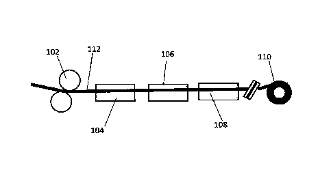
110.
[0055] In the pretreatment unit 104, the surface of the conductor
112, is preferably
prepared by media blasting. The preferred media is sand, however, glass beads,
ilmenite, steel
shot, could also be used. The media blasting is followed by air-wiping to blow
the particulate
materials off the conductor 112. An air-wipe consists of jets of air blown on
to the conductor
112 at an angle and in a direction opposing the direction of travel of the
conductor 112. The air
jets create a 360 ring of air that attaches to the circumference of the
conductor 112 and wipes
the surface with the high velocity of air. In this case, as the conductor
exits the pretreatment unit
104, any particles on the conductor 112 are wiped and blown back into the
pretreatment unit 104.
The air jet typically operates at about 60 to about 100 PSI, preferably about
70-90 PSI, more
.
preferably about 80 PSL The air jet preferably has a velocity (coming out of
the nozzles) of
about 125 mph to about 500 mph, more preferably about 150 mph to about 400
mph, and most
preferably about 250 mph to about 350 mph. After the air-wipe, number of
particles, that are
greater than 10 microns in size, on the surface of the conductor are lower
than 1,000 per square
feet of the conductor surface, preferably less than 100 per square feet of the
surface. After the air
wipe, the conductor is preferably heated, e.g. by a heating oven, UV, 112, E-
beam, open flame,
CA 3 0 4 8 2 7 4 2 0 1 9 - 0 7 - 02
=
WO 2014/025420
PCT/US2013/037433
and the like. The heating can be accomplished by single or multiple units. In
a preferred
embodiment, the drying/curing occurs by direct flame application. Here, the
cable is passed
directly through a flame to heat the cable surface to a temperature above
ambient temperature.
High heating temperature in pretreatment allows for a lower heating
temperature later in the
drying/curing unit. However, the heating should not be too severe that it
affects the quality of
the coating (e.g. adherence, evenness, blistering etc.). Here, it is
preferable that the conductor
not be heated above about 140 C, more preferably no more than about 120 C.
[0056] Once the
surface of the conductor 112 is prepared, it is ready for coating. The
coating process takes place in the coating unit, where the cable passes
through a flooded die that
deposits a liquid suspension of the coating onto the prepared surface. Figures
11-13 show a
depiction of an annular shaped flooded die 200. The coating suspension is fed
to the die 200 via
a tube 206. As the conductor 112 passes though the center opening 204 of the
flooded die 200,
the coating suspension coats the conductor 112 via opening ports in the inner
surface 202 of the
die 200. Preferably, the flooded die 200 contains two or more, preferably
four, more preferably
six, opening ports evenly spaced around the circumference of the inner surface
202. Once the
conductor 112 exits the flooded die, it then passes through another air wipe
to remove excess
coating suspension and to spread the coating evenly around the conductor. In
the case of a
stranded conductor, the air wipe allows the coating to penetrate the grooves
between the strands
on the surface of the conductor. This air wipe preferably operates at the same
condition as that
for the air wipe in the pretreatment unit 104,
(00571 Once the
conductor 112 is coated, it passes through the drying/curing unit 108.
The drying/curing can be accomplished by air or by using hot air of the
temperature of up to
1000 C and/or the line speed of between about 9 feet/min to about 500
feet/min, preferably
16
CA 3048274 2019-07-02
81785602
about 10 feet/min to about 400 feet/rain, depending on the metal alloy used in
the conductor.
The drying process may be gradual drying, rapid drying, or direct flame
application. The drying
or curing also can be accomplished by other techniques, like a heating oven,
UV, IR, 13-beam,
chemical, or liquid spray and the like. The drying can be accomplished by
single or multiple
units. It also can be vertical or horizontal or at a specific angle. In a
preferred embodiment, the
drying/curing occurs by direct flame application. Here, the cable preferably
passes directly
through a flame to heat the cable surface to a temperature of up to about 150
C, preferably up to
about 120 C. Once dried/cured, the coated conductor is wound on a roller 110
for storage.
[0058] The continuous process, if operated for an individual strand
(instead of the whole
cable), preferably operates at a line speed of up to about 2500 ft/rein,
preferably about 9 to about
2000 ft/min, more preferably about 10 to about 500 ft/min, most preferably
about 30 to about
300 ft/rein.
[00591 The overhead conductor coating of embodiments of the present
invention can be used
in composite core conductor designs. Composite core conductors are used due to
their lower sag at higher
operating temperatures and higher strength to weight ratio. Reduced conductor
operating
temperatures due to the coating can further lower sag of the conductors and
lower degradation of
polymer resin in the composite. Examples for composite cores can be found,
e.g., in U.S. Patents
Nos. 7,015,395,7,438,971, and 7,752,754.
[0060] The coated conductor exhibits improved heat dissipation.
Emissivity is the
relative power of a surface to emit heat by radiation, and the ratio of the
radiant energy emitted
by a surface to the radiant energy emitted by a blackbody at the same
temperature. Emittance is
the energy radiated by the surface of a body per unit area. Emissivity can be
measured, for
17
CA 3048274 2019-07-02
81785602
example, by the method disclosed in U.S. Patent Application Publication No.
2010/0076719 to
Lawry et al.
[0061] Without further description, it is believed that one of ordinary
skill in the art can,
using the preceding description and the following illustrative examples, make
and utilize the
compounds of the present invention and practice the claimed methods. The
following example is
given to illustrate the present invention. It should be understood that the
invention is not to be
limited to the specific conditions or details described in this example.
Example 1
[0062] Computer simulation studies was performed using different E/A
(Emissivity to
Absorptivity ratio) values, to measure the reduction in operating temperature
of the conductor for
the same peak current. The E/A ratios were considered as the surface property
of the conductor
which is modified by coating. Table 1 tabulates the simulation results for
various designs of
overhead conductor:
18
CA 3048274 2019-07-02
. .
. ,
III =
wo 20141025420 . PCTMS2013/037433
Table 1: Simulation Results
_
Simulation L Rail AMR Symbol Units Case
I. Case 2 Case 3 Case 4 Case 5 Case 6 Case 7
WA Ratio E/A .5 / .5 .3 / 3 .9 / .9
.7/.5 _ .8 / .4 .9/.3
Number conductors per bundle I. 1 1 1 _ 1 1 1
Peak Current (per conductor) I amps 970 970 970 970 970
970 970
Sub-conductor temperature Tc =C 74 75 73 70 67 64
63
Sub-conductor Resistance at Tc R ohms/mile 0.14 _ 0.14
0.14 014 0.14 013 0.12
Power bass PL
kW/mile 115.37 _ 1.15.60 _ 115.03 113.92 112.68 111 '37 I 311.03
. . . = . - .
.= .
Simulation L CuitewACSR Symbol Units Case
1 Case 2 Case 3 Case 4 Case 5 _ Case 6 Case?
E/A Ratio E/A , .5 / .5 -31.3 .91.9
, .7/5 _ .8 / .4 .9/.3 .9/.2
Number conductors per bundle 1 1 1 1 1 , 1 1
Peak Current (per conductor) I amps 1040 3.040 _ 1040
1040 _ 1040 1040 1040
Sub-conductor temperature Tc C 75 76 74 71 _ 68 , 64
63
Sub-conductor Resistance atTe R ohms/mile 0.11 0.11. 0.11
0.11 _ 0.11 0.11 0.11
Power Loss PL
kW/mile 121.54 _ 121.86 121.13 319.98 11&65 11739 116.70
.= : = . . .
Simulation 3: Lapwing ACSR Symbol Units Case
1 Case 2 Case 3 Case 4 Case 5 Case 6 Case 7
E/A Ratio E/A .5 / .5 3/.3 .91.9 .7/.5
.2/.4 .91.3 .9 / .2
Number conductors per bundle 1 1 1 1 _ 1 1 1
Peak Current (per conductor) I amps , 1335 1335 1335
1335 _ 1335 1335 1335
Sub-conductor temperature Tc C 75 76 74 71 67 64 ,
62
Sub-conductor Resistance atTc R ohms/mile , 0.08 0.08 0.08
0.07 _ (107 0.07 0.07
Power Loss PL kW/mile 134.28
134.63 133.83 132.55 131.08 _ 129.71 129.03
=
: i . = i :
Simulation 4: Bluebhd =ft Symbol Units Case
1 Case 2 Case 3 Case 4 Cases Case 6 Case?
EM Ratio E/A , .5 I .5 .3/.3 .9/.9
.71.5 _ .81.4 .9/-3 .9/2
Nu mberconductors per bundle , 1 1 1 _ 1 _ 1 1 1
õ
Peak Current (per conductor) I , amps 1620 1620 1620 1620
. 1620 1620 1620
Sub-condudor temperature Tc C , 75 76 74 70 _ 67
63 61
Sub-condudor Resistance atTc R ohms/mile 0.06 0.06 0.06
0.05 0.05 0.05 0.05
Power Loss Pl.
kWfmile 145.76 146.11 145.28 143.87 142.32 140.87 140,14
. i= . = = =.= =
Simulation 5: Drake ACSR Symbol Units Case
1 Case 2 Case 3 Case 4 , Case 5 Case 6 Case 7
E/A Ratio E/A .5/.5 .3/.3 .9/.9 7/5
.8/.4 -9/3 5/1
Number conductors per bundle 1 _ 1 1 1 1 1 1
-
Peak Current (per conductor) I amps 900 900 900 900 900
900 900 _
Sub-conductor temperature Tc 't 74 75 73 70 67 64
62 ,
Sub-conductor Resistance atTc Ft ohms/mile 0.14 0.14 0.14
0.14 , 0.14 0.33 0.33 õ
Power Loss PL
kW/mile 112.42 112.63 112.07 110.97 109.79 108.66 108.05
Other conditions .Arribient Temperature: 25
C, Wind Speed: 2 ft/s = r- I
19
CA 3 0 4 82 74 2 01 9 -0 7 -02
IP .
WO 2014/025420 PCT/ITS2013/037433
Example 2
[00631 A coating was prepared by mixing Sodium silicate (20 weight %),
Silicon dioxide
(37 weight %) with Boron Carbide as a heat radiating agent (3 weight %) and
Water (40 weight
%). The coating composition is applied to a metal substrate having an
emissivity of higher than
0.85. A current is applied through the metal substrate with a 1 mil coating
thickness and an
uncoated metal substrate to measure the performance improvement of the
coating. The test
apparatus is shown in FIG. 5 and mainly consisted of a 60Hz ac current source,
a true RMS
clamp-on current meter, a temperature datalog device and a timer. Testing was
conducted within
a 68" wide x 33" deep windowed safety enclosure to control air movement around
the sample.
An exhaust hood was located 64" above the test apparatus for ventilation.
[0064] The sample to be tested was connected hi series with an ac
current source through
a relay contact controlled by a timer. The timer was used to activate the
current sourceand
controlled the time duration of the test. The 60Hz ac current flowing through
the sample was
monitored by a true RMS clamp-on current meter. A thermocouple was used to
measure the
surface temperature of the sample. Using a spring clamp, the tip of the
thermocouple was kept
firmly in contacted with the center surface of the sample. In case of
measurement on coated
sample, the coating was removed at the area where thermocouple made the
contact with the
sample to get accurate measurement of the temperature of the substrate. The
thermocouple
CA 3048274 2019-07-02
= =
WO 2014/025420 PCT/US2013/037433
temperature was monitored by a datalog recording device to provide a
continuous record of
temperature change.
[0065] Both uncoated and coated substrate samples were tested for
temperature rise on
this test set-up under identical experimental conditions. The current was set
at a desired level
and was monitored during the test to ensure a constant current is flowing
through the samples.
The timer was set at a desired value and the temperature datalog recording
device was set to
record temperature at a recording interval of one reading per second.
[0066] The metal component for the uncoated and coated samples was from
the same
source material and lot of Aluminum 1350. The finished dimensions of the
uncoated sample
were 12.0"(L)x0.50"(W)x0.027"(1). The finished dimensions of the coated
samples were
12.0"(L)x0.50"(W)x0.029"(T). The increase in thickness and width was due to
the thickness of
the applied coating.
[0067] The uncoated sample was firmly placed into the test set-up and
the thermocouple
secured to the center portion of the sample. Once that was completed, the
current source was
switched on and was adjusted to the required ampacity load level. Once that
was achieved the
power was switched off. For the test itself, once the timer and datalog device
were all properly
set, the timer was turned on to activate the current source, thus, starting
the test. The desired
current flowed through the sample and the temperature started rising. The
surface temperature
change of the sample was automatically recorded by the datalog device. Once
the testing period
was completed, the timer automatically shut down the current source, thus,
ending the test.
[0068] Once the uncoated sample was tested, it was removed from the set-
up and
replaced by the coated sample. The testing resumed, malcing no adjustments to
the power supply
current device. The same current level was passed through the coated sample.
21
CA 3 0 4 8274 20 1 9-0 7-02
1 I
WO 2014/025420 PCT/1JS2013/037433
[00691 The temperature test data was then accessed from the datalog
device and analyzed
using a computer. Comparing the results from the uncoated sample tests with
those from the
coated tests was used to determine the comparative emissivity effectiveness of
the coating
material. The results of the test are shown in FIG. 6.
Example 3
[0070] Wind effects on temperature rise of the two #4 AWG solid
aluminum coated
conductors were evaluated at a current of 180 amps. A fan with three speeds
was used to
simulate the wind and the wind blew directly to the conductor being tested
from 2 feet away.
The test method circuit diagram is showed in FIG. 7. Both coated and uncoated
conductors were
tested under 180 amps, solar light, and wind; and the test results are shown
in Table 2. The
coated conductor was 35.6%, 34.7% and 26.1% cooler than the uncoated when
subjected to no
wind, low wind, and high wind, respectively. The speed of the wind had a
little impact on the
coated conductor but a 13% impact on the uncoated.
Table 2: Wind effect on coated and uncoated conductor's temperature at 180
amps.
180 amps Temperature Rise ( C)
Uncoated Coated Difference Difference (%)
No Wind 174 112 62 35.6
Low Wind 101 66 35 34.7
High Wind 88 65 23 26.1
22
CA 3048274 2019-07-02
1110
WO 20141025420 PCT/US2013/037433
[00711 Wind effects on temperature rise of the two #4 AWG solid aluminum
conductors
were evaluated at 130 amps current. The uncoated and coated conductors were
tested under no
wind, low wind and high wind, respectively, along with 130 amps current and
solar light. The
tests results are summarized in Table 3. The coated conductor was 29.9%, 133%
and 175 %
cooler than the uncoated conductor when subjected to no wind, low wind and
high wind
respectively.
Table 3: Wind effect on coated and uncoated conductor's temperature at 130amps
Temperature Rise ( C)
130 amps
Uncoated Coated Difference Difference (%)
No Wind 108 76 32 29.9
Low Wind 60 52 8 13.3
High Wind 57 47 10 17.5
Example 4
[0072] Tests were performed on coated and uncoated 2/0 AWG solid
aluminium and 795
kcmil AAC Arbutus conductor samples. The Current Cycle Test method Was
performed in
accordance with ANSI C119.4-2004 as adapted herein.
[0073] CONDUCTOR TEST SAMPLES:
1) 2/0 AWG Solid Aluminum Conductor coated with coating composition
disclosed in
Example 2. Thickness of the coating is 1 mil.
2) Uncoated 2/0 AWG Solid Aluminum Conductor
23
CA 3048274 2019-07-02
=
WO 2014/025420 PCT/US2013/037433
3) 795 kcmil Arbutus All-Aluminum Conductor coated with coating composition
disclosed in Example 2. Thickness of the coating is I mil.
4) Uncoated 795 kcmil Arbutus All-Aluminum Conductor
5) Aluminum Plate (electrical grade bus)
[0074] TEST LOOP ASSEMBLY: A series loop was formed with six identically
sized four
foot conductor specimens (three uncoated and three coated), plus an additional
suitable conductor
routed through the current transformer. The series loop consisted of two runs
of three identically
sized conductor specimens, alternating between coated and uncoated, welded
together with an
equalizer installed between conductor specimens to provide equipotential
planes for resistance
measurements. The equalizers ensured permanent contacts between all conductor
strands.
Equalizers (2" x 3/8" x L75" for 2/0 solid aluminum and 3" x3/8" x 3.5" for
795 AAC Arbutus)
were fabricated from aluminum bus. Holes the size of the connecting conductor
were drilled into
the equalizers. Adjacent conductor ends were welded to the equalizers to
complete the series loop.
A larger eqnaiizer (10" x 3/8" x 1.75" for 2/0 solid aluminium and 12" x 3/8"
x 3.5" for 795 AAC
Arbutus) was used at one end to connect the two runs, while the other end was
connected to an
additional conductor routed through the current transformer. The loop
configuration is depicted in
FIG. 7.
[0075] The test loop assembly was located at least I ft. from any wall
and at least 2 ft. from
the floor and ceiling. Adjacent loops were located at least 1 ft. from each
other and were energized
separately.
[0076] TEMPERATURE MEASUREMENT: The temperature of each conductor
specimen was monitored simultaneously at specified intervals over the course
of the test. The
temperature was monitored using Type T thermocouples and a Data Logger. One
thermocouple
24
CA 3 0 4 8274 201 9 -0 7 -02
= =
WO 2014/025420 PCT/CS2013/037433
was attached to the each conductor at midpoint on the specimen in the 12
o'clock position. One
specimen of each sample had additional thermocouples connected to the sides of
the specimen at
the 3 and 6 o'clock positions. One thermocouple was located adjacent to the
series loop for
ambient temperature measurements.
[0077] CURRENT SETTING: The conductor current was set at appropriate
ampacity to
produce a temperature of 100 C to..105 C above ambient air temperature at the
end of a heating
period for the uncoated conductor specimen. Since the uncoated conductor and
the coated
conductor were placed in series in the test assembly, the same current passed
through both samples.
The first few heat cycles were used to set the proper ampacity to produce the
desired temperature
rise. A heat cycle consisted of one hour of heating followed by one hour of
cooling for the 2/0
AWG solid aluminium loop, and one and a half hours of heating followed by one
and a half hours
of cooling for the 795 stranded aluminium loop.
[0078] TEST PROCEDURE: The test was conducted in accordance with the
Current Cycle
Test Method, ANSI C119.4-2004, except that the test was performed for a
reduced number of heat
cycles (at least fifty cycles were performed). Ambient temperature was
maintained at 2 C.
Temperature measurements were recorded continuously during the heat cycles.
Resistance was
measured at the end of the heating cycle and prior to the next heating cycle,
after the conductor
returned to room temperature.
[0079] TEST RESULT: The coated 2/0 AWG Solid Aluminium Conductor and
795 kcmil
Arbutus All-Aluminium Conductor showed lower temperatures (more than 20 C)
than the uncoated
conductors. The temperature difference data were captured in FIG. 8 and FIG.
9, respectively.
Example 5
CA 3048274 2019-07-02
=
WO 2014/025420 PCI1US2013/037433
[0080] An aluminum substrate was coated with various coating
compositions as
described below and summarized in Table 4. The coating compositions have a
color spectrum
ranging from white to black.
[0081] Aluminum Control: Uncoated aluminum substrate made from 1350
Aluminum
Alloy.
[0082] Coating 2: Polyurethane based coating having solids content of
56 weight %,
available from Lord Corporation as grade Aeroglaze A276.
[0083] Coating 3: PVDF based coating with Fluoropolymer /Acrylic resin
ratio of 70:30
available from Arkema as Kynar ARC and 10 weight % of Titanium dioxide powder.
[0084] Coating 4: Coating containing of 75 weight % of Sodium silicate
solution in water
(containing 40% solid) and 25 weight % of Zinc oxide available from US Zinc.
[0085] Coating 5: Coating containing 72.5 weight % of Sodium silicate
solution in water
(containing 40% solid) and 12.5 weight % of Aluminum Nitride AT powder (having
particle size
distribution of D 10% 0.4 to 1.4 microns, D 50% 7 toll microns, D 90% 17 to 32
microns)
available from H.C. Starck, 12.5 weight % of Silicon carbide and 2.5 weight %
of reactive
amino silicone resin (grade SF1706) available from Momentive Performance
Material holding
Inc.
[0086] Coating 6: Coating containing 87.5 weight % of Silicone based
coating (Grade
236) available from Dow corning and 12.5 weight % of Silicon carbide.
[0087] Coating 7: Coating containing Silicate binder (20 weight %),
Silicon dioxide (37
weight %) and Boron Carbide (3 weight %) and Water (40 weight %)
[0088] Coating 8: Coating containing Potassium silicate (30 weight %),
Tri Calcium
Phosphate (20% weight %), Mixed metal oxide pigment (5%) and Water (45%)
26
CA 3048274 2019-07-02
411
WO 20141025420 PCT/US2013/037433
[0089] Color of the samples was measured on the Ls, a*, b* scale using
Spectro-guide
45/0 gloss made by BYK-Gardner USA.
100901 Samples were tested for Solar Reflectance (R) and Absorptivity
(A) as per ASTM
E903. Emissivity (E) of the samples was measured as per ASTM E408 at the
temperature of
300K. The aluminum substrate of 50mm length x 50hnm width x 2mm thickness
coated with 1
mil thickness coating were used for the measurements of Solar Reflectance,
Absorptivity,
Emissivity.
[0091] The coated samples were tested for their ability to reduce
operating temperature
of the conductor when compared to a bare aluminum substrate as described in
Example 2 using
electrical current setting of 95 amps. To study the effect of Solar energy on
the operating
temperature of the conductor, light bulb simulating Solar energy spectrum was
plareri above the
test sample in addition to the electrical current applied to the test sample
and the test sample
temperature was recorded. Standard Metal Halide 400 Watt Bulb (Model
MH400/T15/HOR/4K)
was used. Distance between the lamp and the bulb was maintained at 1 ft. The
results are
tabulated as "Electrical + Solar". Results with the light bulb turned off
while electrical current
turned on are tabulated as "Electrical".
[0092] Heat aging performance of the coating was carried out by
placing the samples in
an air circulating oven maintained at 325 C for a period of 1 day and 7 days.
After the heat
aging was complete, the samples were placed at room temperature of 21 C for a
period of 24
hours. The samples were then bent on different cylindrical mandrels sized from
higher diameter
to lower diameter and the coatings were observed for any visible cracks at
each of the mandrel
size. Sample was considered as "Pass" if it showed no visible cracks when bent
on a mandrel of
diameter of 10 inches or less.
27
CA 3048274 2019-07-02
,
. .
III III
WO 2014/025420 PC1'/US2013/037433
Table 4.
= 1 2 3 4 5 6 r I
Ccadng Type ,. Organic Organic Inorganic .
inorganic Inorganic Inorganic Inorganic
[stadia Binder Uncoated P'J PVDF Silicate
Silicate Methyl Silicone Silicate Silicate
Msual Colour White White White , Grey Grey
Dark Gray Black
Measured tear Values .
1.* 92.65 78555 84.925 67.48
60.12 43.495 1554
a. -1.7 -0.655 -0.27 õ -0.8 -1.68
-0.49 0.17
It* 0.075 . -0.605 -2.185 2.41
-4.04 -2.015 -0:13
Solar Reactance 10 0.701 0.74 - 0.63 0.35 0.21 0.14
0.02
Solar Absorptly1 ty (AI 0.299 0.26 0.37 0.65 õ 0.79 0.86
028
Bnissivity ( E 1 0.161 0.847 0.859 0.86 0.86
0.882 0.91
Temperature Reduction .
Electrical 109 893110.7%) 37(22%) ,
90(19%) 66(42%) 64145%) 89.5 ( 193%) 84125%)
Becalm! a- Solar 117.5 90.5122.9%1 .1023(12.7%) 102(14%) 71(40%)
71(46.5%) 92(21.7%) 865(262%)
Flexibility: Mandrel Test
Initial (Before heat ageing I Pass Pass Pass ., Pass ,
Pass Pass Pass
After Heat ageing 325 des.0 ( 1 day) Fall Fall , Fall Pass
Pass Pass Pass
After Heat ageing 325 cleat ( 7 days) Fall Fall Fall
Pass Pass
[0093]
While particular embodiments have been chosen to illustrate the invention; it
will be
understood by those skilled in the art that various changes and modifications
can be made therein
without departing from the scope of the invention as defined in the appended
claims.
28
CA 3 0 4 8274 2 0 1 9 - 0 7 -02