Note: Descriptions are shown in the official language in which they were submitted.
CA 03048732 2019-06-27
BLADE-REPLACEABLE CUTTING TOOL
Field of the Invention
The present invention relates to hand tools, and in particular to a blade-
replaceable
cutting tool.
Description of the Prior art
The cutting tool, as a common tool, has the blade which will be chipped or
damaged
after several times of usage so that the whole tool loses its functions,
resulting in a
large waste of resources. If the blade is replaceable, it can better extend
the service
life of the tool.
For some cutting tools with simple structures, the blade thereof is easy to be
assembled and disassembled, and the users can remove and replace the blade by
themselves. However, for some cutting tools with complex structures, such as a
ratchet pipe cutter, the non-professional person cannot operate to replace the
blade,
and once the blade is damaged, the whole cutting tool will lose its value.
Those skilled in the art devote themselves to developing a new blade-
replaceable
cutting tool, and regardless of whether the cutting component thereof is a
simple fixed
blade structure or a complex ratchet blade structure, the blade can be easily
and
quickly replaced, thereby effectively extending the service life of the
cutting tool to
avoid a waste of resources.
Summary of the Invention
An object of the present invention is to provide a blade-replaceable cutting
tool to
solve the technical problems of the cutting tools with complex structures in
the prior
art, such as the ratchet pipe cutter, of which the blade is difficult to be
replaced, and
the whole cutting tool will be unusable after the blade is damaged.
01279-17006PICA
CA 03048732 2019-06-27
In order to solve the above-mentioned technical problems, the present
invention
provides a blade-replaceable cutting tool including: a first handheld portion;
a second
handheld portion, rotatably connected to the first handheld portion; a blade
mounting
plate, rotatably mounted to the first handheld portion; and a blade,
detachably
mounted to the blade mounting plate.
Further, in a different implementation, the blade mounting plate includes a
blade
mounting plate body having a front end mounted with the blade; and an arcuate
plate
provided at a rear end of the blade mounting plate body and being a portion of
the
ratchet.
Further, in a different implementation, the arcuate plate is a portion of a
ratchet, which
includes: ratchet teeth, provided on an arcuate side wall of the arcuate
plate; and a
ratchet tooth clearance, provided between any two adjacent ratchet teeth;
wherein the
second handheld portion is provided with a first buckle and/or a second buckle
on a
side facing the first handheld portion, which is snapped into any one of the
ratchet
tooth clearances.
Further, in a different implementation, the blade mounting plate includes a
blade
mounting plate latch provided at the front end of the blade mounting plate
body and
connected to the middle of the arcuate plate; and a blade mounting plate
bayonet
provided between the blade mounting plate latch and the arcuate plate and
having an
opening direction facing the blade.
Further, in a different implementation, the blade includes: a ridge portion; a
cutting
edge portion, provided integrally with the ridge portion; a blade latch,
provided at the
edge of the blade, provided opposite to the cutting edge portion, and snapped
into the
blade mounting plate bayonet; and a blade bayonet, provided between the blade
latch
and the cutting edge portion, the blade mounting plate latch is snapped into
the blade
2 01279-17006PICA
CA 03048732 2019-06-27
bayonet.
Further, in a different implementation, the blade mounting plate includes an
elastic
sheet mounting notch provided on a side of the arcuate plate remote from the
arcuate
side wall and having an opening direction facing the blade; the blade includes
a blade
fixing bayonet provided opposite to the elastic sheet mounting notch.
Further, in a different implementation, the elastic sheet mounting notch
includes a first
notch portion having an opening located on a side of the arcuate plate remote
from the
arcuate side wall; and a second notch portion communicated to the first notch
portion
and provided perpendicular to the first notch portion.
Further, in a different implementation, the blade mounting plate includes a
first latch
of the blade mounting plate provided at the front end of the blade mounting
plate
body; a second latch of the blade mounting plate provided at the middle of the
blade
mounting plate body and corresponding to the ridge portion; a third latch of
the blade
mounting plate provided at the middle of the blade mounting plate body and
corresponding to the cutting edge portion; a first bayonet of the blade
mounting plate
provided between the first latch of the blade mounting plate and a locking
member;
and a second bayonet of the blade mounting plate provided between the second
latch
of the blade mounting plate and the third latch of the blade mounting plate;
the blade
includes: a ridge portion; a cutting edge portion provided integrally with the
ridge
portion; a first latch of the blade protruding from the ridge portion and
snapped into
the first bayonet of the blade mounting plate; a second latch of the blade
protruding
from the ridge portion and snapped into the second bayonet of the blade
mounting
plate; a first bayonet of the blade provided at the front end of the ridge
portion; the
first latch of the blade mounting plate is snapped into the first bayonet of
the blade
and is tangent to the first latch of the blade; a second bayonet of the blade
provided at
the rear end of the ridge portion; the second latch of the blade mounting
plate is
snapped into the second bayonet of the blade; and a third bayonet of the blade
3 01279-17006PICA
CA 03048732 2019-06-27
provided at the rear end of the cutting edge portion; the third latch of the
blade
mounting plate is snapped into the third bayonet of the blade and is tangent
to the
second latch of the blade .
Further, in a different implementation, the blade mounting plate includes an
elastic
member mounting notch communicated to the first bayonet of the blade mounting
plate; and a locking member mounting notch communicated to the elastic member
mounting notch; the blade includes a blade locking latch protruding from the
first
latch of the blade; and a blade locking bayonet enclosed by the blade locking
latch,
the first latch of the blade and the ridge portion; the blade-replaceable
cutting tool
further includes a locking member including the following components which are
integrally provided: a locking lever, sliding within the locking member
mounting
notch and having a front end snapped into the blade locking bayonet; a locking
block
connected to the middle of the locking lever and sliding within the elastic
member
mounting notch; and an elastic member provided within the elastic member
mounting
notch, and one end of the elastic member is connected to a side wall of the
locking
block and the other end thereof is connected to an inner side wall of the
elastic
member mounting notch.
Further, in a different implementation, the blade-replaceable cutting tool
further
includes a first clamping plate attached and fixed to one side of the blade
mounting
plate; and a second clamping plate attached and fixed to the other side of the
blade
mounting plate; wherein the connection between the blade and the blade
mounting
plate is sandwiched between the first clamping plate and the second clamping
plate.
Further, in a different implementation, the first clamping plate is provided
with a first
kidney-shaped slot; the second clamping plate is provided with a second
kidney-shaped slot provided opposite to the first kidney-shaped slot; wherein
the first
kidney-shaped slot and the second kidney-shaped slot are provided opposite to
a
portion of the first notch portion and the blade fixing bayonet.
4 01279-17006PICA
CA 03048732 2019-06-27
Further, in a different implementation, the blade-replaceable cutting tool
further
includes a toggle lever successively passing through the first kidney-shaped
slot, the
elastic sheet mounting notch and/or the blade fixing bayonet and the second
kidney-shaped slot; and an elastic sheet provided within the elastic sheet
mounting
notch; one end of the elastic sheet is fixed to the blade mounting plate and
the other
end thereof is tangent to the side wall of the toggle lever.
Further, in a different implementation, the toggle lever includes a first
toggle member
including the following components which are formed integrally: a first toggle
knob
being tangent to the first clamping plate and exposed to the outside of the
first
clamping plate; and a first toggle post passing through the first kidney-
shaped slot;
and a second toggle member including the following components which are formed
integrally: a second toggle knob being tangent to the second clamping plate;
and a
second toggle post passing through the second kidney-shaped slot and connected
to
the first toggle post.
Further, in a different implementation, the elastic sheet includes the
following
components which are formed integrally: a bent portion provided within the
second
notch portion; a linear portion provided within the first notch portion; and
one end of
the linear portion is connected to the bent portion and the other end thereof
is tangent
to the side wall of the toggle lever.
Further, in a different implementation, the blade-replaceable cutting tool
further
includes a blade pin mounting hole penetrating through the blade and located
at a
portion of the ridge portion close to the blade mounting plate; a first
clamping plate
pin mounting hole penetrating through the first clamping plate and provided
opposite
to the blade pin mounting hole; a second clamping plate pin mounting hole
penetrating through the second clamping plate and provided opposite to the
blade pin
mounting hole; a pin successively passing through the second clamping plate
pin
01279-17006PICA
CA 03048732 2019-06-27
mounting hole, the blade pin mounting hole and the first clamping plate pin
mounting
hole; one end of the pin is provided with a pin cap and a side wall of the
other end
thereof is provided with a sunken positioning slot; a positioning ball
provided at the
opening of the positioning slot; and a positioning spring having one end
connected to
the bottom of the positioning slot and the other end connected to the
positioning ball.
Further, in a different implementation, the blade-replaceable cutting tool
further
includes a first control hole penetrating through the first clamping plate and
provided
opposite to the locking block; and a third toggle member protruding from a
side of the
locking block facing the first clamping plate and passing through the first
control
hole.
Further, in a different implementation, the blade-replaceable cutting tool
further
includes a second control hole penetrating through the second clamping plate
and
provided opposite to the front end of the locking lever; and a fourth toggle
member
protruding from a side of the front end of the locking lever facing the second
clamping plate and passing through the second control hole.
Further, in a different implementation, the first clamping plate includes a
first
clamping plate arcuate plate provided at the rear end of the first clamping
plate and
being a portion of the ratchet; first clamping plate ratchet teeth provided on
an arcuate
side wall of the first clamping plate arcuate plate; and a first clamping
plate ratchet
tooth clearance provided between any two adjacent first clamping plate ratchet
teeth.
Further, in a different implementation, the second clamping plate includes a
second
clamping plate arcuate plate provided at the rear end of the second clamping
plate and
being a portion of the ratchet; second clamping plate ratchet teeth provided
on an
arcuate side wall of the second clamping plate arcuate plate; and a second
clamping
plate ratchet tooth clearance provided between any two adjacent second
clamping
plate ratchet teeth.
6 01279-17006PICA
CA 03048732 2019-06-27
Further, in a different implementation, the blade-replaceable cutting tool
further
includes a first fastener fixing the first clamping plate and the second
clamping plate
to both sides of the blade mounting plate; and a second fastener successively
fixing a
first side wall of the first handheld portion, the first clamping plate, the
blade
mounting plate, the second clamping plate, and a second side wall of the first
handheld portion together.
Further, in a different implementation, the first side wall of the first
handheld portion
is provided with a first side wall through hole of the first handheld portion;
the second
side wall of the first handheld portion is provided with a second side wall
through
hole of the first handheld portion; the first clamping plate is provided with
a first
clamping plate through hole; the second clamping plate is provided with a
second
clamping plate through hole; the blade mounting plate is provided with a blade
mounting plate through hole; wherein the second fastener successively passes
through
the first side wall through hole of the first handheld portion, the first
clamping plate
through hole, the blade mounting plate through hole, the second clamping plate
through hole, and the second side wall through hole of the first handheld
portion.
Further, in a different implementation, the first handheld portion includes a
first side
wall of the first handheld portion; a second side wall of the first handheld
portion
provided opposite to the first side wall of the first handheld portion; and a
first
handheld portion opening cavity enclosed by the first side wall of the first
handheld
portion and the second side wall of the first handheld portion and having an
opening
direction facing the second handheld portion; wherein the blade mounting plate
and
the blade are provided within the first handheld portion opening cavity.
Further, in a different implementation, the first handheld portion further
includes a
first arcuate groove provided at the edge of the first side wall of the first
handheld
portion; and a second arcuate groove provided at the edge of the second side
wall of
7 01279-17006PICA
CA 03048732 2019-06-27
the first handheld portion and provided opposite to the first arcuate groove;
wherein
the first arcuate groove and the second arcuate groove are provided on both
sides of
the opening of the first handheld portion opening cavity, respectively.
Further, in a different implementation, the second handheld portion includes a
first
side wall of the second handheld portion; a second side wall of the second
handheld
portion provided integrally with the first side wall of the second handheld
portion and
opposite to the first side wall of the second handheld portion; and a second
handheld
portion opening cavity having an opening direction facing the first handheld
portion.
Further, in a different implementation, the blade-replaceable cutting tool
includes a
first elastic member having one end fixed to the first handheld portion and
the other
end fixed to the blade mounting plate; and a second elastic member having one
end
fixed to the first handheld portion and the other end fixed to the second
handheld
portion.
Further, in a different implementation, the blade-replaceable cutting tool
further
includes a first pin perpendicularly assembled on the inner side of the two
side walls
of the first handheld portion; the first handheld portion and the second
handheld
portion are rotatably sleeved on the first pin; a first buckle having a rear
end rotatably
sleeved on the first pin and a front end snapped into any one of the ratchet
tooth
clearances; and a first elastic member having one end connected to the first
handheld
portion and the other end connected to the first buckle. The first elastic
member is a
torsion spring.
Further, in a different implementation, the blade-replaceable cutting tool
further
includes a second pin perpendicularly assembled on the inner side of the two
side
walls of the second handheld portion; a second buckle having a rear end
rotatably
sleeved on the second pin and a front end snapped into any one of the ratchet
tooth
clearances; and a second elastic member having one end connected to the second
8 01279-17006NCA
CA 03048732 2019-06-27
handheld portion and the other end connected to the second buckle. The second
elastic
member is a torsion spring sleeved on the second pin and having one end
connected to
the first handheld portion and the other end detachably connected to the
second
buckle.
Further, in a different implementation, the blade-replaceable cutting tool
further
includes a third elastic member having one end fixed to the first handheld
portion and
the other end fixed to the blade mounting plate. The third elastic member is
an
extension spring.
In order to solve the above-mentioned technical problems, the present
invention
further provides another blade-replaceable cutting tool, including: a first
handheld
portion; a second handheld portion rotatably connected to the first handheld
portion;
and a ratchet blade detachably and rotatably mounted to the first handheld
portion.
Further, in a different implementation, the blade-replaceable cutting tool
further
includes a detachable pin provided at the connection between the first
handheld
portion and the ratchet blade, and the first handheld portion and the ratchet
blade can
be rotated about the detachable pin.
Further, in a different implementation, the blade-replaceable cutting tool
further
includes a first side wall through hole of the first handheld portion
penetrating
through the first side wall of the first handheld portion; a second side wall
through
hole of the first handheld portion penetrating through the second side wall of
the first
handheld portion; and a blade through hole penetrating through the ratchet
blade;
wherein the detachable pin successively passes through the first side wall
through
hole of the first handheld portion, the blade through hole and the second side
wall
through hole of the first handheld portion.
Further, in a different implementation, the detachable pin includes a hollow
shaft
9 01279-17006PICA
CA 03048732 2019-06-27
including the following components which are formed integrally: a hollow shaft
sleeve successively passing through the first side wall through hole of the
first
handheld portion, the blade through hole and the second side wall through hole
of the
first handheld portion; and a shaft sleeve base exposed to the outside of the
first side
wall of the first handheld portion; and a rotating member including the
following
components which are formed integrally: a rotating shaft inserted and
threadedly
connected to the hollow shaft sleeve; and a rotating shaft base exposed to the
outside
of the second side wall of the first handheld portion and having an outer
surface
provided with a flat or cross-shaped groove.
Further, in a different implementation, the detachable pin includes a nut
exposed to
the outside of the first side wall of the first handheld portion; and a screw
having a
front end inserted and threadedly connected to the nut and a rear end provided
with a
screw base; the screw base is exposed to the outside of the second side wall
of the
first handheld portion and has an outer surface provided with a flat or cross-
shaped
groove.
Further, in a different implementation, the ratchet blade includes a cutting
portion
provided at the front end of the ratchet blade; an arcuate plate provided at
the rear end
of the ratchet blade; and a connecting portion used for connecting the cutting
portion
and the arcuate plate and rotatably connected to the first handheld portion.
Further, in a different implementation, the cutting portion includes a ridge
portion
facing the outside of the first handheld portion; and a cutting edge portion
facing a
second opening of the first handheld portion.
Further, in a different implementation, the cutting edge portion is linear or
arcuate.
Further, in a different implementation, the arcuate plate is a portion of the
ratchet,
which includes ratchet teeth provided on the arcuate side wall of the arcuate
plate; and
01279-17006PICA
CA 03048732 2019-06-27
a ratchet tooth clearance provided between any two adjacent ratchet teeth;
wherein the
second handheld portion is provided with a first buckle and/or a second buckle
on the
side facing the first handheld portion, which is snapped into any one of the
ratchet
tooth clearances.
Further, in a different implementation, the arcuate plate includes an arcuate
plate snap
hole penetrating through one end of the arcuate plate and snapped by one end
of the
third elastic member.
Further, in a different implementation, the connecting portion includes a
connecting
portion snap slot sunken to the side wall of the connecting portion and
snapped by one
end of the third elastic member.
Further, in a different implementation, the first handheld portion includes a
first side
wall of the first handheld portion; a second side wall of the first handheld
portion
provided opposite to the first side wall of the first handheld portion; and a
first
handheld portion opening cavity enclosed by the first side wall of the first
handheld
portion and the second side wall of the first handheld portion; which
includes: a first
opening of the first handheld portion facing the second handheld portion; and
a
second opening of the first handheld portion facing the outside of the first
handheld
portion; wherein a portion of the ratchet blade is provided within the first
handheld
portion opening cavity.
Further, in a different implementation, the first handheld portion further
includes a
first arcuate groove provided at the edge of the first side wall of the first
handheld
portion; a second arcuate groove provided at the edge of the second side wall
of the
first handheld portion and provided opposite to the first arcuate groove;
wherein the
first arcuate groove and the second arcuate groove are provided on both sides
of the
second opening, respectively.
I 01279-17006PICA
CA 03048732 2019-06-27
Further, in a different implementation, the second handheld portion includes a
first
side wall of the second handheld portion; a second side wall of the second
handheld
portion provided integrally with the first side wall of the second handheld
portion and
opposite to the first side wall of the second handheld portion; and a second
handheld
portion opening cavity having an opening direction facing the first handheld
portion.
Further, in a different implementation, the blade-replaceable cutting tool
further
includes a first pin perpendicularly assembled on the inner side of the two
side walls
of the first handheld portion; thc first handheld portion and the second
handheld
portion are rotatably sleeved on the first pin; a first buckle having a rear
end rotatably
sleeved on the first pin and a front end snapped into any one of the ratchet
tooth
clearances; a first elastic member having one end connected to the first
handheld
portion and the other end connected to the first buckle.
Further, in a different implementation, the first elastic member is an
extension spring.
Further, in a different implementation, the blade-replaceable cutting tool
further
includes a second pin perpendicularly assembled on the inner side of the two
side
walls of the second handheld portion; a second buckle having a rear end
rotatably
sleeved on the second pin and a front end snapped into any one of the ratchet
tooth
clearances; and a second elastic member having one end connected to the second
handheld portion and the other end connected to the second buckle.
Further, in a different implementation, the second elastic member is a torsion
spring
sleeved on the second pin and having one end connected to the first handheld
portion
and the other end detachably connected to the second buckle.
Further, in a different implementation, the blade-replaceable cutting tool
further
includes a third elastic member having one end fixed to the first handheld
portion and
the other end fixed to the ratchet blade.
12 01279-17006PICA
CA 03048732 2019-06-27
Further, in a different implementation, the third elastic member is a torsion
spring
sleeved on a torsion spring mounting shaft, one end of the third elastic
member is
fixed to the first handheld portion and the other end thereof is connected to
the ratchet
blade; both ends of the torsion spring mounting shaft are perpendicularly
fixed to the
inner side of the two side walls of the first handheld portion.
Further, in a different implementation, one end of the torsion spring is fixed
to the
first handheld portion and the other end thereof is snapped into the arcuate
plate snap
hole or the connecting portion snap slot of the ratchet blade.
The beneficial effect of the present invention is to provide a blade-
replaceable cutting
tool, which can achieve the quick replacement of the blade and is simple to
operate
and convenient to use; it requires lower manipulative ability, and an ordinary
user can
replace the blade, which can effectively extend the overall service life of
the cutting
tool.
Brief Description of the Drawings
Figure 1 is a schematic view of the overall structure of Embodiment 1 of the
present
invention in the locked state;
Figure 2 is a structural schematic view of Embodiment 1 of the present
invention with
the first side wall of the first handheld portion removed;
Figure 3 is a structural schematic view of the first handheld portion
according to
Embodiment 1 of the present invention;
Figure 4 is a structural schematic view of the second handheld portion
according to
Embodiment 1 of the present invention;
I 3 01279-17006PICA
CA 03048732 2019-06-27
Figure 5 is a structural schematic view of some components inside the first
and
second handheld portions according to Embodiment '1 of the present invention;
Figure 6 is a structural schematic view of the blade mounting plate according
to
Embodiment 1 of the present invention;
Figure 7 is an exploded structural schematic view of the cutting structure and
the first
handheld portion according to Embodiment 1 of the present invention;
Figure 8 is a structural schematic view of the second fastener according to
Embodiment 1 of the present invention;
Figure 9 is a structural schematic view of the blade according to Embodiment 1
of the
present invention;
Figure 10 is a structural schematic view of the toggle lever according to
Embodiment
1 of the present invention;
Figure 11 is a structural schematic view of the elastic sheet according to
Embodiment
1 of the present invention;
Figure 12 is an exploded structural schematic view of the cutting structure
according
to Embodiment 1 of the present invention;
Figure 13 is a schematic view of the overall structure of Embodiment 1 of the
present
invention in the unlocked state;
Figure 14 is a schematic view of the overall structure of the cutting
structure
according to Embodiment 2 of the present invention;
14 01279-17006PICA
CA 03048732 2019-06-27
Figure 15 is an exploded structural schematic view of the cutting structure
according
to Embodiment 2 of the present invention;
Figure 16 is a structural schematic view of the blade mounting plate according
to
Embodiment 2 of the present invention;
Figure 17 is a structural schematic view of the blade according to Embodiment
2 of
the present invention;
Figure 18 is a structural schematic view of the pin according to Embodiment 2
of the
present invention;
Figure 19 is an exploded structural schematic view of the cutting structure
according
to Embodiment 3 of the present invention;
Figure 20 is a schematic view of the overall structure of the cutting
structure
according to Embodiment 3 of the present invention;
Figure 21 is a structural schematic view of the cutting structure according to
Embodiment 3 of the present invention with the second clamping plate removed;
Figure 22 is a structural schematic view of the blade mounting plate according
to
Embodiment 3 of the present invention;
Figure 23 is a structural schematic view of the blade according to Embodiment
3 of
the present invention;
Figure 24 is a structural schematic view of the elastic member and the locking
key
according to Embodiment 3 of the present invention;
15 01279-17006PICA
CA 03048732 2019-06-27
Figure 25 is a schematic view of the overall structure of Embodiment 4 of the
present
invention in the open state;
Figure 26 is a structural schematic view of the first handheld portion
according to
Embodiment 4 of the present invention;
Figure 27 is a structural schematic view of the first handheld portion and
some
components inside the first handheld portion according to Embodiment 4 of the
present invention;
Figure 28 is a structural schematic view of the second handheld portion
according to
Embodiment 4 of the present invention;
Figure 29 is a structural schematic view of the components inside the first
and second
handheld portions according to Embodiment 4 of the present invention;
Figure 30 is a structural schematic view of the detachable pin according to
Embodiment 4 of the present invention;
Figure 31 is a structural schematic view of the ratchet blade according to
Embodiment
4 of the present invention;
Figure 32 is a schematic view of the overall structure of Embodiment 5 of the
present
invention;
Figure 33 is an exploded structural schematic view of a part of the structure
of
Embodiment 5 of the present invention;
Figure 34 is a structural schematic view of the components inside the first
and second
handheld portions according to Embodiment 5 of the present invention;
16 01279-17006PICA
CA 03048732 2019-06-27
Figure 35 is a structural schematic view of the ratchet blade according to
Embodiment
of the present invention;
Figure 36 is a structural schematic view of the detachable pin according to
Embodiment 5 of the present invention.
The components in the figures are identified as follows:
I first handheld portion, 2 second handheld portion, 3 blade mounting plate, 4
blade, 5
ratchet blade; 6 detachable pin, 7 first clamping plate, 8 second clamping
plate, 9 first
fastener, 10 second fastener; 11 first side wall of the first handheld
portion, 12 second
side wall of the first handheld portion, 13 first handheld portion opening
cavity; 14
first pin, 15 first buckle, 16 first elastic member, 17 first arcuate groove;
18 second
arcuate groove, 19 third elastic member, 20 torsion spring mounting shaft; 21
first
side wall of the second handheld portion, 22 second side wall of the second
handheld
portion, 23 second handheld portion opening cavity; 24 second pin, 25 second
buckle,
26 second elastic member, 27 handheld portion fixing device; 31 blade mounting
plate
body, 32 arcuate plate, 33 blade mounting plate through hole, 34 blade
mounting plate
latch; 35 blade mounting plate bayonet, 36 elastic sheet mounting notch; 41
ridge
portion, 42 cutting edge portion, 43 blade latch, 44 blade bayonet, 45 blade
fixing
bayonet, 46 blade pin mounting hole; 51 cutting portion, 52 arcuate plate, 53
connecting portion, 54 blade through hole; 61 hollow shaft, 62 rotating
member, 63
nut, 64 screw, 65 screw base; 71 first clamping plate through hole, 72 first
kidney-shaped slot, 73 first clamping plate pin mounting hole, 74 first
control hole; 75
first clamping plate arcuate plate, 76 first clamping plate ratchet teeth, 77
first
clamping plate ratchet tooth clearance; 81 second clamping plate through hole,
82
second kidney-shaped slot, 83 second clamping plate pin mounting hole, 84
second
control hole; 85 second clamping plate arcuate plate, 86 second clamping plate
ratchet
teeth, 87 second clamping plate ratchet tooth clearance; 91 toggle rod, 92
elastic sheet,
17 01279-17006PICA
CA 03048732 2019-06-27
93 locking member, 94 fourth elastic member; 95 pin, 96 positioning ball, 97
positioning spring, 98 pin cap, 99 positioning slot; 101 nut base, 102 stem
nut, 103
screw base, 104 screw; 111 first side wall through hole of the first handheld
portion;
121 second side wall through hole of the first handheld portion; 131 first
opening of
the first handheld portion, 132 second opening of the first handheld portion;
311 first
latch of the blade mounting plate, 312 second latch of the blade mounting
plate; 313
third latch of the blade mounting plate, 314 first bayonet of the blade
mounting plate;
315 second bayonet of the blade mounting plate, 316 elastic member mounting
notch,
317 locking member mounting notch; 321 ratchet teeth, 322 ratchet tooth
clearance;
361 first notch portion, 362 second notch portion; 411 first latch of the
blade, 412
second latch of the blade, 413 first bayonet of the blade, 414 second bayonet
of the
blade; 415 third bayonet of the blade, 416 blade locking latch, 417 blade
locking
bayonet; 511 ridge portion, 512 cutting edge portion, 521 ratchet teeth, 522
ratchet
tooth clearance; 531 connecting portion snap slot, 532 arcuate plate snap
hole; 611
hollow shaft sleeve, 612 shaft sleeve base, 621 rotating shaft, 622 rotating
shaft base;
911 first toggle knob, 912 first toggle post, 913 second toggle knob, 914
second
toggle post; 921 linear portion, 922 bent portion; 931 locking lever, 932
locking block,
933 third toggle member, 934 fourth toggle member.
Detailed Description of the Preferred Embodiments
The preferred embodiments of the present invention will be described fully
hereafter
with reference to the accompanying drawings of the description, so that the
technical
contents thereof will be more clearly and easily understood. The present
invention
may be embodied in many different forms of embodiments, and the protection
scope
thereof is not limited to the embodiments mentioned herein.
In the drawings, the components having same structures are denoted by same
reference numerals, and the components having similar structures or functions
are
denoted by similar reference numerals. The dimension and thickness of each of
the
components shown in the drawings are shown arbitrarily, and the present
invention
18 01279-17006MA
CA 03048732 2019-06-27
does not limit the dimension and thickness of each of the components. In order
to
make the illustration clearer, the thickness of the components is
appropriately
exaggerated in some places in the drawings.
The directional words mentioned in the present invention such as upper, lower,
front,
rear, left, right, inner, outer, side, top, bottom, top end, bottom end,
distal end, etc., are
only the directions in the drawings and are only intended to explain and
illustrate the
present invention, but not to limit the protection scope of the present
invention.
When a certain component is described as being "on" another component, the
component may be placed directly on another component; an intermediate
component
may also be present, on which the component is placed, and the intermediate
component is placed on another component. When a component is described as
being
"mounted to" or "connected to" another component, the two may be understood to
be
directly "mounted" or "connected", or one component is indirectly "mounted to"
or
"connected to" another component via an intermediate component.
Embodiment 1
As shown in Figures 1 to 2, this embodiment provides a blade-replaceable
cutting tool,
including a first handheld portion 1, a second handheld portion 2, a blade
mounting
plate 3, and a blade 4.
As shown in Figure 3, the first handheld portion 1 includes a first side wall
of the first
handheld portion 11 and a second side wall of the first handheld portion 12
which are
opposite to each other and provided integrally, and the first side wall of the
first
handheld portion 11 and the second side wall of the first handheld portion 12
enclose
a first handheld portion opening cavity 13 having an opening direction facing
the
second handheld portion 2; the blade mounting plate 3 and a portion of the
blade 4 are
provided within the first handheld portion opening cavity 13.
19 01279-17006MA
CA 03048732 2019-06-27
As shown in Figure 4, this embodiment further includes a first pin 14, a first
buckle
15, and a first elastic member 16, and the first pin 14 is perpendicularly
assembled to
the inner side of the two side walls 11, 12 of the first handheld portion 1;
the first
handheld portion 1 and the second handheld portion 2 are rotatably sleeved on
the
first pin 14. The rear end of the first buckle 15 is rotatably sleeved on the
first pin 14
and the front end thereof is snapped into any one of the ratchet tooth
clearances 322.
One end of the first elastic member 16 is connected to the first handheld
portion 1 and
the other end thereof is connected to the first buckle 15, the first elastic
member 16 in
this embodiment is preferably a torsion spring, so that the first buckle 15
can be
rotated within a certain range. As shown in Figures 4 to 5, the end of the
first
handheld portion 1 mounted with the blade 4 further includes a first arcuate
groove 17
and a second arcuate groove 18, and the first arcuate groove 17 is provided at
the edge
of the first side wall of the first handheld portion 11; the second arcuate
groove 18 is
provided at the edge of the second side wall of the first handheld portion 12
and is
provided opposite to the first arcuate groove 17; and the first arcuate groove
17 and
the second arcuate groove 18 are provided on both sides of the opening of the
first
handheld portion opening cavity 13, respectively, and the two arcuate grooves
17, 18
are used for placing and fixing a pipe to achieve the function of cutting the
pipe. The
blade 4 directly faces the first handheld portion opening cavity 13, and the
blade 4
falls into the first handheld portion opening cavity 13 after the cutting
process is
completed.
As shown in Figures 4 to 5, the second handheld portion 2 is rotatably
connected to
the first handheld portion 1. The second handheld portion 2 includes a first
side wall
of the second handheld portion 21 and a second side wall of the second
handheld
portion 22 which are opposite to each other and provided integrally, and the
first side
wall of the second handheld portion 21 and the second side wall of the second
handheld portion 22 enclose a second handheld portion opening cavity 23, and
the
second handheld portion opening cavity 23 has an opening direction facing the
first
20 01279-17006PICA
CA 03048732 2019-06-27
handheld portion 1.
As shown in Figures 4 to 5, this embodiment further includes a second pin 24,
a
second buckle 25, and a second elastic member 26, and the second pin 24 is
perpendicularly assembled to the inner side of two side walls 21, 22 of the
second
handheld portion 2. The rear end of the second buckle 25 is rotatably sleeved
on the
second pin 24 and the front end thereof is snapped into any one of the ratchet
tooth
clearances 322; one end of the second elastic member 16 is connected to the
second
handheld portion 2 and the other end thereof is connected to the second buckle
25.
The second elastic member 26 is preferably a torsion spring which is sleeved
on the
second pin 24, and one end of the torsion spring is connected to the first
handheld
portion 1 and the other end thereof is detachably connected to the second
buckle 25,
so that the second buckle 25 can be rotated within a certain range.
In this embodiment, the first buckle 15 or the second buckle 25, under the
action of
the first elastic member 16 or the second elastic member 26, is snapped into
the
ratchet tooth clearance at an appropriate position, and during the cutting of
the pipe,
the two buckles can assist the blade in exerting a force to cut the pipe
located between
the blade 4 and the two arcuate grooves 17, 18, thereby achieving a labor-
saving
effect. Pipe will vibrate during the cutting, resulting in discomfort of
user's hand, the
first elastic member 16 or the second elastic member 26 may have the function
of
damping and cushioning. The first elastic member 16 and the second elastic
member
26 may assist in closing or opening of the first handheld portion 1 and the
second
handheld portion 2, and the operation principle thereof is the same as that of
the same
type of pipe cutter and will not be described here.
As shown in Figure 2, this embodiment further includes a third elastic member
19
having one end connected to the first handheld portion 1 and the other end
connected
to the blade mounting plate 3, and the third elastic member 19 is preferably
an
extension spring. In this embodiment, during the opening or closing of the
first
21 01279-17006PICA
CA 03048732 2019-06-27
handheld portion 1 and the second handheld portion 2, the third elastic member
19
assists in exerting a force or limits the range of movement of the blade
mounting plate
3 and the blade 4, which can ensure that the opening angle is within an
appropriate
range to prevent the components from being damaged and to reduce the security
risk
during use.
The distal end of the second handheld portion 2 is provided with a handheld
portion
fixing device 27 having one end hinged to the distal end of the second
handheld
portion 2 and the other end detachably mounted to the distal end of the first
handheld
portion 1 for closing the first handheld portion 1 and the second handheld
portion 2.
As shown in Figure 6, the blade mounting plate 3 is rotatably mounted to the
first
handheld portion 1, the blade mounting plate 3 includes a blade mounting plate
through hole 33, and the blade mounting plate 3 can be rotated with the
central axis of
the blade mounting plate through hole 33 as the axis of rotation. The blade 4
is
detachably mounted to the blade mounting plate 3, preferably, the blade 4 is
in the
same plane as the blade mounting plate 3, the blade 4 is integrally combined
with the
blade mounting plate 3, and the outer edge shape, the working principle and
the
functions thereof are substantially equivalent to that of a complete ratchet
blade. The
blade mounting plate 3 includes a blade mounting plate body 31 having a front
end
mounted with the blade 4 and a rear end provided with an arcuate plate 32, the
arcuate
plate 32 is a portion of the ratchet, the arcuate plate 32 includes an arcuate
side
portion and a non-arcuate side portion, and the side wall thereof includes an
arcuate
side wall and a non-arcuate side wall; the arcuate side wall of the arcuate
plate 32 is
provided with a plurality of equally spaced ratchet teeth 321, and the arcuate
side wall
of the arcuate plate 32 faces the second handheld portion 2; a ratchet tooth
clearance
322 is formed between any two adjacent ratchet teeth 321 so that the first
buckle 15 or
the second buckle 25 provided within the second handheld portion opening
cavity 23
is snapped into any one of the ratchet tooth clearances 322.
22 01279-17006PICA
CA 03048732 2019-06-27
This embodiment is opened and closed when in use, the first handheld portion 1
and
the second handheld portion 2 are relatively rotated, and the arcuate plate 32
of the
blade mounting plate 3 cooperates with the first buckle 15 and the second
buckle 25,
so that the blade 4 can achieve an effective cutting operation, the working
principle of
which is the same as that of the existing ratchet type pipe cutter and will
not be
described here.
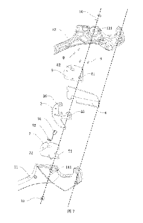
As shown in Figure 7, this embodiment further includes a first clamping plate
7 and a
second clamping plate 8 for fixing the blade 4 and the blade mounting plate 3.
The
first clamping plate 7 is attached and fixed to one side of the blade mounting
plate 3;
the second clamping plate 8 is attached and fixed to the other side of the
blade
mounting plate 3; the connection between the blade 4 and the blade mounting
plate 3
is sandwiched between the first clamping plate 7 and the second clamping plate
8.
This embodiment further includes a first fastener 9 and a second fastener 10.
The first
fastener 9 fixes the first clamping plate 7 and the second clamping plate 8 to
both
sides of the blade mounting plate 3; the edges of the first clamping plate 7,
the second
clamping plate 8 and the blade mounting plate 3 are provided with a plurality
of
fastener mounting holes (not shown) in the positions corresponding to them,
respectively, and the first fastener 9 includes, but is not limited to, a
rivet or a bolt,
and successively passes through the first clamping plate 7, the blade mounting
plate 3,
and the second clamping plate 8, thereby assembling the first clamping plate
7, the
second clamping plate 8 and the blade mounting plate 3 together.
The second fastener 10 successively assembles the first side wall of the first
handheld
portion 11, the first clamping plate 7, the blade mounting plate 3, the second
clamping
plate 8, and the second side wall of the first handheld portion 12 together,
so that the
blade mounting plate 3 is hinged to the first handheld portion 1, both of
which may be
relatively rotated.
23 01279-17006PICA
CA 03048732 2019-06-27
Specifically, the first side wall of the first handheld portion 11 is provided
with a first
side wall through hole of the first handheld portion 111; the second side wall
of the
first handheld portion 12 is provided with a second side wall through hole of
the first
handheld portion 121; the first clamping plate 7 is provided with a first
clamping plate
through hole 71; the second clamping plate 8 is provided with a second
clamping
plate through hole 81; and the blade mounting plate 3 is provided with a blade
mounting plate through hole 33. The second fastener 10 includes, but is not
limited to,
a bolt, and successively passes through the first side wall through hole of
the first
handheld portion 111, the first clamping plate through hole 71, the blade
mounting
plate through hole 33, the second clamping plate through hole 81, and the
second side
wall through hole of the first handheld portion 121.
As shown in Figures 7 to 8, the second fastener 10 is preferably a bolt
including a nut
portion and a screw portion, the nut portion includes a nut base 101 and a
stem nut
102 which are formed integrally, and the screw portion includes a screw base
103 and
a screw 104 which are formed integrally. The nut base 101 is attached to the
outer
surface of the first side wall of the first handheld portion 11; and the screw
base 103 is
attached to the outer surface of the second side wall of the first handheld
portion 12.
The stem nut 102 is perpendicularly fixed to the nut base 101, and
successively passes
through the first side wall through hole of the first handheld portion 111,
the first
clamping plate through hole 71, the blade mounting plate through hole 33, the
second
clamping plate through hole 81, and the second side wall through hole of the
first
handheld portion 121. The stem nut 102 is provided with a threaded cavity at
its
center, and the screw 104 is rotatably and threadedly connected to the
threaded cavity
for adjusting the relative position of the nut base 101 and the screw base
103.
The blade mounting plate 3, the blade 4, the first clamping plate 7, and the
second
clamping plate 8 collectively constitute a cutting structure, and the cutting
structure of
this embodiment is a ratchet type component.
24 01279-17006PICA
CA 03048732 2019-06-27
As shown in Figure 6, in this embodiment, the blade mounting plate 3 includes
a
blade mounting plate latch 34 and a blade mounting plate bayonet 35. The blade
mounting plate latch 34 is provided at the front end of the blade mounting
plate body
31 and is connected to the non-arcuate side portion at the middle of the
arcuate plate
32; the blade mounting plate bayonet 35 is provided between the blade mounting
plate
latch 34 and the arcuate plate 32 and has an opening direction facing the
blade 4.
As shown in Figures 6 and 9, in this embodiment, the blade 4 includes a ridge
portion
41 and a cutting edge portion 42 which are provided integrally, and further
includes a
blade latch 43 and a blade bayonet 44. The blade latch 43 is provided at the
edge of
the blade 4 and is provided opposite to the cutting edge portion 42 and is in
the same
direction as the cutting edge portion 42, and the blade latch 43 is snapped
into the
blade mounting plate bayonet 35. The blade bayonet 44 is provided between the
blade
latch 43 and the cutting edge portion 42 and the blade mounting plate latch 34
is
snapped into the blade bayonet 44, so that the blade mounting plate 3 is
assembled
integrally with the blade 4 and remains relatively stable.
As shown in Figures 6, 7 and 9, the blade mounting plate 3 further includes an
elastic
sheet mounting notch 36, the elastic sheet mounting notch 36 is provided on a
side of
the arcuate plate 32 remote from the arcuate side wall and has an opening
direction
facing the blade 4, and is used to assemble the elastic sheet. The elastic
sheet
mounting notch 36 includes a first notch portion 361 and a second notch
portion 362,
the opening of the first notch portion 361 is located on a side of the arcuate
plate 32
remote from the arcuate side wall; and the second notch portion 362 is
communicated
to the first notch portion 361 and is provided perpendicular to the first
notch portion
361. The blade 4 includes a blade fixing bayonet 45 which is provided opposite
to the
elastic sheet mounting notch 35, specifically, which directly faces a portion
of the first
notch portion 361.
As shown in Figure 7, the first clamping plate 7 is provided with a first
kidney-shaped
25 01279-17006PICA
CA 03048732 2019-06-27
slot 72, the second clamping plate 8 is provided with a second kidney-shaped
slot 82
provided opposite to the first kidney-shaped slot 72; the first kidney-shaped
slot 72
and the second kidney-shaped slot 82 are provided opposite to a portion of the
first
notch portion 361 and the blade fixing bayonet 45, which constitute a toggle
through
hole penetrating through all of the first clamping plate 7, the blade mounting
plate 3
and the second clamping plate 8 for placing the toggle lever 91.
As shown in Figures 7 and 10, this embodiment further includes a toggle lever
91, and
the toggle lever 91 successively passes through the first kidney-shaped slot
72, the
elastic sheet mounting notch 36 and/or the blade fixing bayonet 45 and the
second
kidney-shaped slot 82. The toggle lever 91 includes a first toggle member and
a
second toggle member which are connected to each other. The first toggle
member
includes a first toggle knob 911 and a first toggle post 912 which are formed
integrally,
and the second toggle member includes a second toggle knob 913 and a second
toggle
post 914 which are formed integrally.
As shown in Figures 1, 2, and 10, the first toggle member and the second
toggle
member are respectively inserted into the first kidney-shaped slot 72 and the
second
kidney-shaped slot 82 from both sides of the blade mounting frame 3 and are
combined into a toggle lever 91. The first toggle knob 911 is tangent to the
first
clamping plate 71 and is exposed to the outside of the first clamping plate 7;
the
second toggle knob 913 is tangent to the second clamping plate 82 and is
exposed to
the outside of the second clamping plate 8. The first toggle post 912 passes
through
the first kidney-shaped slot 72; and the second toggle post 914 passes through
the
second kidney-shaped slot 82 and is connected to the first toggle post 912.
The middle
of the first toggle post 912 is a threaded cavity, and the second toggle post
914 is
inserted into the cavity of the first toggle post 912. The first toggle knob
911 is
exposed to the outside of the first handheld portion 1 so that the user can
replace the
blade by using the toggle lever 91.
26 01279-17006PICA
CA 03048732 2019-06-27
As shown in Figures 11 and 12, this embodiment further includes an elastic
sheet 92
provided within the elastic sheet mounting notch 36; one end of the elastic
sheet 92 is
fixed to the blade mounting plate 3 and the other end thereof is tangent to
the side
wall of the toggle lever 91, and specifically, the elastic sheet 92 is tangent
to the side
wall of the first toggle post 912 for pressing the first toggle post 912
against the blade
fixing bayonet 45 so that the blade 4 is fixed to the blade mounting plate 3.
When the
first toggle knob 911 is toggled, the first toggle post 912 is disengaged from
the blade
fixing bayonet 45 and the blade 4 can be removed in the direction of the
cutting edge
thereof.
The elastic sheet 92 includes a linear portion 921 and a bent portion 922
which are
formed integrally, and the linear portion 921 is provided within the first
notch portion
361; the bent portion 922 is provided within the second notch portion 362; one
end of
the linear portion 921 is connected to the bent portion 922 and the other end
thereof is
tangent to the side wall of the toggle lever 91 (the first toggle post 912).
As shown in
Figures 1, 11 and 12, when the blade 4 is mounted on the blade mounting plate
3, the
toggle lever 91 is in the locked position, the elastic sheet 92 is slightly
deformed, and
the toggle lever 91 is pressed in the blade fixing bayonet 45. Since the blade
latch 43
is snapped into the blade mounting plate bayonet 35 and the blade mounting
plate
bayonet 34 is snapped into the blade bayonet 44, the blade 4 is locked on the
blade
mounting plate 3 so that the cutting tool according to this embodiment can be
used
normally, and the specific use method thereof is the same as that of the blade
fixed
pipe cutter and will not be described here.
As shown in Figure 13, when the blade 4 is damaged and the blade 4 needs to be
replaced, it is only necessary to toggle the toggle lever 91 from the locked
position 93
to the unlocked position, the elastic sheet 92 is greatly deformed, and the
toggle lever
91 is disengaged from the blade fixing bayonet 45 and slides into the elastic
sheet
mounting notch 36, whereby the user can pull out the blade 4 of the blade
mounting
plate 3 in the direction of the ridge portion 41 and then mount a spare blade
into the
27 01279-17006P1CA
CA 03048732 2019-06-27
blade mounting plate 3, release the toggle lever 91 so that it slides back to
locked
position under the action of the elastic sheet 92, and lock the newly mounted
spare
blade on the blade mounting plate 3, so that the cutting tool can be used
normally,
completing the entire blade replacement process.
The beneficial effect of this embodiment is to provide a blade-replaceable
cutting tool,
which can achieve the quick replacement of the blade and is simple to operate
and
convenient to use; it requires lower manipulative ability, and an ordinary
user can
replace the blade, which can effectively extend the overall service life of
the cutting
tool.
Embodiment 2
This embodiment provides a blade-replaceable cutting tool, including most of
the
technical features of Embodiment 1, except that the features of the cutting
structure
are different, as shown in Figures 14 to 15, the cutting structure is
collectively
constituted by a blade mounting plate 3, a blade 4, a first clamping plate 7,
and a
second clamping plate 8.
Specifically, the cutting structure according to this embodiment is also a
ratchet type
component, and the blade mounting plate 3 is rotatably mounted to the first
handheld
portion 1; the blade 4 is detachably mounted to the blade mounting plate 3.
As shown in Figure16, the blade mounting plate 3 includes a blade mounting
plate
body 31 having a front end mounted with the blade 4 and a rear end provided
with an
arcuate plate 32, the arcuate plate 32 is a portion of the ratchet, the
arcuate plate 32
includes an arcuate side portion and a non-arcuate side portion, and the side
wall
thereof includes an arcuate side wall and a non-arcuate side wall; the arcuate
side wall
of the arcuate plate 32 is provided with a plurality of equally spaced ratchet
teeth 321,
a ratchet tooth clearance 322 is formed between any two adjacent ratchet teeth
321 so
28 01279-17006PICA
CA 03048732 2019-06-27
that the first buckle 15 or the second buckle 25 provided within the second
handheld
portion opening cavity 23 is snapped into any one of the ratchet tooth
clearances 322.
The blade mounting plate 3 includes a blade mounting plate through hole 33,
and the
blade mounting plate 3 can be rotated with the central axis of the blade
mounting
plate through hole 33 as the axis of rotation.
In this embodiment, the blade mounting plate 3 includes a blade mounting plate
latch
34 and a blade mounting plate bayonet 35. The blade mounting plate latch 34 is
provided at the front end of the blade mounting plate body 31 and is connected
to the
non-arcuate side portion at the middle of the arcuate plate 32; and the blade
mounting
plate bayonet 35 is provided between the blade mounting plate latch 34 and the
arcuate plate 32 and has an opening direction facing the blade 4.
As shown in Figures 15 to 17, in this embodiment, the blade 4 includes a ridge
portion
41 and a cutting edge portion 42 which are provided integrally, and further
includes a
blade latch 43 and a blade bayonet 44. The blade latch 43 is provided at the
edge of
the blade 4 and is provided opposite to the cutting edge portion 42 and is in
the same
direction as the cutting edge portion 42, and the blade latch 43 is snapped
into the
blade mounting plate bayonet 35. The blade bayonet 44 is provided between the
blade
latch 43 and the cutting edge portion 42 and the blade mounting plate latch 34
is
snapped into the blade bayonet 44, so that the blade mounting plate 3 is
assembled
integrally with the blade 4 and remains relatively stable.
This embodiment does not include the toggle lever 91 and the elastic sheet 92,
the
blade mounting plate 3 also does not include the elastic sheet mounting notch
36, the
first clamping plate 7 is not provided with the first kidney-shaped slot 72,
and the
second clamping plate 8 is also not provided with the second kidney-shaped
slot 82.
As shown in Figures 15 and 17, this embodiment includes a blade pin mounting
hole
29 01279-17006PICA
CA 03048732 2019-06-27
46, a first clamping plate pin mounting hole 73, and a second clamping plate
pin
mounting hole 83. The blade pin mounting hole 46 penetrates through the blade
4 and
is located at the portion of the ridge portion 41 close to the blade mounting
plate 3.
The first clamping plate pin mounting hole 73 penetrates through the first
clamping
plate 7 and is provided opposite to the blade pin mounting hole 46; and the
second
clamping plate pin mounting hole 83 penetrates through the second clamping
plate 8
and is provided opposite to the blade pin mounting hole 46.
As shown in Figure 18, this embodiment includes a pin 95, a positioning ball
96, and
a positioning spring 97. The pin 95 successively passes through the second
clamping
plate pin mounting hole 83, the blade pin mounting hole 46, and the second
clamping
plate pin mounting hole 73, and one end of the pin 95 is provided with a pin
cap 98
and the side wall of the other end thereof is provided with a sunken
positioning slot 99.
The positioning ball 96 is provided at the opening of the positioning slot 99;
one end
of the positioning spring 97 is fixedly connected to the bottom of the
positioning slot
99 and the other end thereof is fixedly connected to the positioning ball 96.
The
diameter of the opening of the positioning slot 99 is slightly smaller than
the diameter
of the positioning ball 96 to prevent the positioning ball 96 from sliding out
of the
positioning slot 99 entirely.
When the blade 4 is mounted on the blade mounting plate 3, the positioning
spring 97
is in a normal shape, the positioning ball 96 protrudes beyond the pin 95, and
the pin
95 passes through both the blade 4 and the blade mounting plate 3; since the
blade
latch 43 is snapped into the blade mounting plate bayonet 35 and the blade
mounting
plate latch 34 is snapped into the blade bayonet 44, the blade 4 is locked on
the blade
mounting plate 3 so that the cutting tool according to this embodiment can be
used
normally, and the specific use method thereof is the same as that of the blade
fixed
pipe cutter and will not be described here.
When the blade 4 is damaged and the blade 4 needs to be replaced, it is only
30 01279-17006PICA
CA 03048732 2019-06-27
necessary to press down the positioning ball 96 and then compress the
positioning
spring 97, and when the positioning ball 96 is fully retracted into the
positioning slot
99, the user can pull out the pin 95 and then pull out the blade 4 in the
direction of the
ridge portion 41, and then mount a spare blade into the blade mounting plate
3, insert
the pin 95, and lock the newly mounted spare blade on the blade mounting plate
3, so
that the cutting tool can be used nonually, completing the entire blade
replacement
process.
The beneficial effect of this embodiment is to provide a blade-replaceable
cutting tool,
which can achieve the quick replacement of the blade and is simple to operate
and
convenient to use; it requires lower manipulative ability, and an ordinary
user can
replace the blade, which can effectively extend the overall service life of
the cutting
tool.
Embodiment 3
This embodiment provides a blade-replaceable cutting tool, including most of
the
technical features of Embodiment 1, except that the features of the cutting
structure
are different, as shown in Figures 19 to 20, the cutting structure is
collectively
constituted by the blade mounting plate 3, the blade 4, the first clamping
plate 7, and
the second clamping plate R.
The blade mounting plate 3 is rotatably mounted to the first handheld portion
1; and
the blade 4 is detachably mounted to the blade mounting plate 3.
As shown in Figures 21 to 24, the blade mounting plate 3 includes a blade
mounting
plate body 31 having a front end mounted with the blade 4 and a rear end
provided
with an arcuate plate 32, the arcuate plate 32 is a portion of the ratchet,
the arcuate
plate 32 includes an arcuate side portion and a non-arcuate side portion, the
side wall
of the arcuate plate 32 includes an arcuate side wall and a non-arcuate side
wall; the
31 01279-17006PICA
CA 03048732 2019-06-27
arcuate side wall of the arcuate plate 32 is provided with a plurality of
equally spaced
ratchet teeth 321, a ratchet tooth clearance 321 is formed between any two
adjacent
ratchet teeth 321 so that the first buckle 15 or the second buckle 25 provided
within
the second handheld portion opening cavity 23 is snapped into any one of the
ratchet
tooth clearances 322. The blade mounting plate 3 includes a blade mounting
plate
through hole 33, and the blade mounting plate 3 can be rotated with the
central axis of
the blade mounting plate through hole 33 as the axis of rotation.
Both the blade mounting plate 3 and the blade 4 are provided with a plurality
of
latches and bayonets which cooperate with each other and form snap structures
correspondingly, so that the blade mounting plate 3 and the blade 4 are
integrally
assembled and remain relatively stable.
In this embodiment, the blade mounting plate 3 includes a first latch of the
blade
mounting plate 311, a second latch of the blade mounting plate 312, and a
third latch
of the blade mounting plate 313. The first latch of the blade mounting plate
311 is
provided at the front end of the blade mounting plate body 31; the second
latch of the
blade mounting plate 312 is provided at the middle of the blade mounting plate
body
31 and corresponds to the ridge portion 41; and the third latch of the blade
mounting
plate 313 is provided at the middle of ,the blade mounting plate body 31 and
corresponds to the cutting edge portion 42.
The blade mounting plate 3 further includes a first bayonet of the blade
mounting
plate 314 and a second bayonet of the blade mounting plate 315; the first
bayonet of
the blade mounting plate 314 is provided between the first latch of the blade
mounting
plate 311 and the locking member 93; and the second bayonet of the blade
mounting
plate 315 is provided between the second latch of the blade mounting plate 312
and
the third latch of the blade mounting plate 313.
The blade 4 includes a ridge portion 41 and a cutting edge portion 42 which
are
32 01279-17006PICA
CA 03048732 2019-06-27
provided integrally, and further includes a first latch of the blade 411, a
second latch
of the blade 412, a first bayonet of the blade 413, a second bayonet of the
blade 414,
and a third bayonet of the blade 415.
The first latch of the blade 411 is protruding from the top of the ridge
portion 41 and
is snapped into the first bayonet of the blade mounting plate 314; and the
second latch
of the blade 412 is protruding from the rear end of the ridge portion 41 and
is snapped
into the second bayonet of the blade mounting plate 315.
The first bayonet of the blade 413 is provided at the front end of the ridge
portion 41;
the first latch of the blade mounting plate 311 is snapped into the first
bayonet of the
blade 413 and is tangent to the first latch of the blade 411. The second
bayonet of the
blade 414 is provided at the rear end of the ridge portion 41; and the second
latch of
the blade mounting plate 312 is snapped into the second bayonet of the blade
414. The
third bayonet of the blade 415 is provided at the rear end of the cutting edge
portion
42; and the third latch of the blade mounting plate 313 is snapped into the
third
bayonet of the blade 415 and is tangent to the second latch of the blade 414.
The blade mounting plate 3 includes an elastic member mounting notch 316 and a
locking member mounting notch 317, and the elastic member mounting notch 316
is
communicated to the first bayonet of the blade mounting plate 314 for mounting
an
elastic member; the locking member mounting notch 317 is communicated to the
elastic member mounting notch 316 for mounting a locking key.
The blade 4 includes a blade locking latch 416 and a blade locking bayonet
417, the
blade locking latch 416 is protruding rearwardly from the first latch of the
blade 411;
the blade locking bayonet 417 is enclosed by the blade locking latch 416, the
first
latch of the blade 411 and the ridge portion 41.
The cutting tool according to this embodiment further includes a locking
member 93
33 01279-17006PICA
CA 03048732 2019-06-27
and a fourth elastic member 94. The locking member 93 includes a locking lever
931
and a locking block 932 which are provided integrally, the locking lever 931
slides
within the locking member mounting notch 316 and has a front end snapped into
the
blade locking bayonet 417; the locking block 932 is connected to the middle of
the
locking lever 931 and slides within the elastic member mounting notch 316. The
locking member 93 is used to lock the blade 4 on the blade mounting plate 3,
and the
blade 4 can be removed from the blade mounting plate 3 by a user when the
locking
member 93 is slid. The fourth elastic member 94 is provided within the elastic
member mounting notch 316, and one end of the fourth elastic member 94 is
connected to the side wall of the locking block 932 and the other end thereof
is
connected to the inner side wall of the elastic member mounting notch 316, and
the
fourth elastic member 94 is preferably a spiral spring. The fourth elastic
member 94
enables the locking member 93 to lock the blade in the normal state so that
the
locking member 93 can slide within the locking member mounting notch 317 under
the action of an external force.
As shown in Figures 19 and 24, the first clamping plate 7 is provided with a
first
control hole 74 which is provided opposite to the locking block 932; and the
side of
the locking block 932 facing the first clamping plate 7 is provided with a
protruded
third toggle member 933; the third toggle member 933 passes through the first
control
hole 74. The second clamping plate 8 is provided with a second control hole 84
which
is provided opposite to the front end of the locking lever 931; and the side
of the front
end of the locking lever 931 facing the second clamping plate 8 is provided
with a
protruded fourth toggle member 934; the fourth toggle member 934 passes
through
the second control hole 84. The third toggle member 933 and the fourth toggle
member 934 are respectively provided on both sides of the blade mounting plate
3 and
exposed to the outside of the blade mounting plate 3 and the first handheld
portion I,
so that the user can toggle the locking member 93 from any direction of the
two sides
of the blade mounting plate 3, so that the locking member 93 slides within the
locking
member mounting notch 317.
34 01279-17006PICA
CA 03048732 2019-06-27
The first clamping plate 7 includes a first clamping plate arcuate plate 75,
first
clamping plate ratchet teeth 76, and a first clamping plate ratchet tooth
clearance 77.
The first clamping plate arcuate plate 75 is provided at the rear end of the
first
clamping plate 7, and the first clamping plate arcuate plate 75 is a portion
of the
ratchet; the first clamping plate ratchet teeth 76 are provided on the arcuate
side wall
of the first clamping plate arcuate plate 75; the first clamping plate ratchet
tooth
clearance 77 is provided between any two adjacent first clamping plate ratchet
teeth
76. The second clamping plate 8 includes a second clamping plate arcuate plate
85,
second clamping plate ratchet teeth 86, and a second clamping plate ratchet
tooth
clearance 87. The second clamping plate arcuate plate 85 is provided at the
rear end of
the second clamping plate 8 and it is a portion of the ratchet; the second
clamping
plate ratchet teeth 86 are provided on the arcuate side wall of the second
clamping
plate arcuate plate 85; the second clamping plate ratchet tooth clearance 87
is
provided between any two adjacent second clamping plate ratchet teeth 86. The
first
clamping plate arcuate plate 75, the second clamping plate arcuate plate 85
and the
arcuate plate 32 of the blade mounting plate 3 have the same shape and size,
the first
clamping plate ratchet tooth clearance 77, the second clamping plate ratchet
tooth
clearance 87 and the ratchet tooth clearance 322 of the blade mounting plate 3
have
the same shape and the corresponding position. The first buckle 15 or the
second
buckle 25 of the second handheld portion 23 is snapped into any one of the
ratchet
tooth clearances 322 and is also snapped into the first clamping plate ratchet
tooth
clearance 77 and the second clamping plate ratchet tooth clearance 87.
During the operation of this embodiment, when the blade 4 is mounted on the
blade
mounting plate 3, the fourth elastic member 94 is slightly deformed, the front
end of
the locking lever 931 is inserted into the blade locking bayonet 417, and
since the first
latch of the blade 411 is snapped into the first bayonet of the blade mounting
plate
314 and the second latch of the blade 412 is snapped into the second bayonet
of the
blade mounting plate 315, the blade 4 is now locked on the blade mounting
plate 3 so
35 01279-17006PICA
CA 03048732 2019-06-27
that the cutting tool according to this embodiment can be used normally, and
the
specific use method thereof is the same as that of the blade fixed pipe cutter
and will
not be described here.
When the blade 4 is damaged and the blade 4 needs to be replaced, the third
toggle
member 933 or the fourth toggle member 934 is toggled, the fourth elastic
member 94
is compressed and then deformed, and the front end of the locking lever 931 is
disengaged from the blade locking bayonet 417, whereby the user can pull out
the
blade 4 of the blade mounting plate 3 in the direction of the cutting edge
portion 42
and then mount a spare blade into the blade mounting plate 3, and release the
third
toggle member 933 or the fourth toggle member 934 so that the front end of the
locking lever 931 is inserted into the blade locking bayonet 417 under the
action of
the fourth elastic member 94, and then lock the newly mounted spare blade on
the
blade mounting plate 3 so that the cutting tool can be used normally,
completing the
entire blade replacement process.
The beneficial effect of this embodiment is to provide a blade-replaceable
cutting tool,
which can achieve the quick replacement of the blade and is simple to operate
and
convenient to use; it requires lower manipulative ability, and an ordinary
user can
replace the blade, which can effectively extend the overall service life of
the cutting
tool.
Embodiment 4
As shown in Figure 25, this embodiment provides a blade-replaceable cutting
tool,
including a first handheld portion 1, a second handheld portion 2, and a
ratchet blade
5. The ratchet blade 5 refers to a blade having a portion of the side wall
designed to be
ratchet-shaped, and the ratchet blade 5 includes an arcuate plate 52, the
arcuate plate
52 is a portion of the ratchet and the arcuate side wall thereof is provided
with a
plurality of uniformly distributed ratchet teeth 521, a ratchet tooth
clearance 522 is
36 01279-17006PICA
CA 03048732 2019-06-27
formed between any two adjacent ratchet teeth 521. In this embodiment, the
blade
mounting plate 3 and the blade 4 in Embodiments 1, 2 or 3 are replaced with
the
ratchet blade 5, and the structure of the ratchet blade 5 is similar to the
structure
formed by the combination of the blade mounting plate 3 and the blade 4.
As shown in Figures 26 to 29, the first handheld portion 1 includes a first
side wall of
the first handheld portion 11 and a second side wall of the first handheld
portion 12
which are opposite to each other and provided integrally, and the first side
wall of the
first handheld portion 11 and the second side wall of the first handheld
portion 12
enclose a first handheld portion opening cavity 13, and the first handheld
portion
opening cavity 13 includes a first opening of the first handheld portion 131
and a
second opening of the first handheld portion 132, and the first opening of the
first
handheld portion 131 faces the direction of the second handheld portion 2; and
the
second opening of the first handheld portion 132 faces the outside of the
first
handheld portion 1; and a portion of the ratchet blade 5 is located within the
first
handheld portion opening cavity 13.
This embodiment further includes a first pin 14, a first buckle 15 and a first
elastic
member 16, the first pin 14 is perpendicularly assembled on the inner side of
the two
side walls 11, 12 of the first handheld portion 1; the first handheld portion
1 and the
second handheld portion 2 are rotatably sleeved on the first pin 14. The rear
end of the
first buckle 15 is rotatably sleeved on the first pin 14 and the front end
thereof is
snapped into any one of the ratchet tooth clearances. One end of the first
elastic
member 16 is connected to the first handheld portion 1 and the other end
thereof is
connected to the first buckle 15, and the first elastic member 16 in this
embodiment is
preferably an extension spring.
The end of the first handheld portion 1 provided with the ratchet blade 5
further
includes a first arcuate groove 17 and a second arcuate groove 18, the first
arcuate
groove 17 is provided at the edge of the first side wall of the first handheld
portion 11;
37 01279-17006P1CA
CA 03048732 2019-06-27
and the second arcuate groove 18 is provided at the edge of the second side
wall of
the first handheld portion 12 and is provided opposite to the first arcuate
groove 17;
the first arcuate groove 17 and the second arcuate groove 18 are provided on
both
sides of the first handheld portion opening cavity 13, respectively, and two
arcuate
grooves are used for placing and fixing a pipe to achieve the function of
cutting the
pipe. The cutting edge of the ratchet blade 5 directly faces the first
handheld portion
opening cavity 13, and the cutting edge falls into the first handheld portion
opening
cavity 13 after the cutting process is completed.
The second handheld portion 2 is rotatably connected to the first handheld
portion 1
and the second handheld portion 2 includes a first side wall of the second
handheld
portion 21 and a second side wall of the second handheld portion 22 which are
opposite to each other and provided integrally, the first side wall of the
second
handheld portion 21 and the second side wall of the second handheld portion 22
enclose a second handheld portion opening cavity 23, and the second handheld
portion opening cavity 23 has an opening direction facing the first handheld
portion I.
This embodiment further includes a second pin 24, a second buckle 25, and a
second
elastic member 26, the second pin 24 is perpendicularly assembled to the inner
side of
the two side walls 21, 22 of the second handheld portion 2. The rear end of
the second
buckle 25 is rotatably sleeved on the second pin 24 and the front end thereof
is
snapped into any one of the ratchet tooth clearances; one end of the second
elastic
member 16 is connected to the second handheld portion 2 and the other end
thereof is
connected to the second buckle 25. The second elastic member 26 is preferably
a
torsion spring which is sleeved on the second pin 24, and one end of the
torsion spring
is connected to the first handheld portion 1 and the other end thereof is
detachably
connected to the second buckle 25.
In this embodiment, the first buckle 15 or the second buckle 25, under the
action of
the first elastic member 16 or the second elastic member 26, is snapped into
the
38 01279-17006PICA
CA 03048732 2019-06-27
ratchet tooth clearance in an appropriate place, and during the cutting of the
pipe, the
two buckles can assist the blade in exerting a force to cut the pipe located
between the
ratchet blade 5 and the two arcuate grooves 17, 18, thereby achieving a labor-
saving
effect.
This embodiment further includes a detachable pin 6 provided at the connection
between the first handheld portion 1 and the ratchet blade 5, the first
handheld portion
1 an the ratchet blade 5 can be rotated about the detachable pin 6 so that the
cutting
tool according to this embodiment can be used normally, and the specific use
method
thereof is the same as that of the blade fixed pipe cutter and will not be
described
here.
The first side wall of the first handheld portion 11 is provided with a first
side wall
through hole of the first handheld portion 111; the second side wall of the
first
handheld portion 12 is provided with a second side wall through hole of the
first
handheld portion 121, and the ratchet blade 5 is provided with a blade through
hole 54,
the detachable pin 6 successively passes through the first side wall through
hole of the
first handheld portion Ill, the blade through hole 54 and the second side wall
through
hole of the first handheld portion 121, the ratchet blade 5 is rotatably
connected to the
first handheld portion 1 via the detachable pin 6.
As shown in Figure 30, the detachable pin 6 includes a hollow shaft 61 and a
rotating
member 62 which are combined together, the rotating member 62 is detachably
assembled to the hollow shaft 61.
The hollow shaft 61 includes a hollow shaft sleeve 611 and a shaft sleeve base
612
which are formed integrally, the hollow shaft sleeve 611 successively passes
through
the first side wall through hole of the first handheld portion Ill, the blade
through
hole 54, and the second side wall through hole of the first handheld portion
121; the
shaft sleeve base 612 is exposed to the outside of the first side wall of the
first
39 01279-
17006PIC14.
CA 03048732 2019-06-27
handheld portion 11.
The rotating member 62 includes a rotating shaft 621 and a rotating shaft base
622
which are formed integrally, the rotating shaft 621 is inserted and threadedly
connected to the hollow shaft sleeve 611; the rotating shaft base 622 is
exposed to the
outside of the second side wall of the first handheld portion 12, and the
outer surface
thereof is provided with a flat or cross-shaped groove.
As shown in Figure 31, the ratchet blade 5 refers to a blade having a portion
of the
side wall designed to be ratchet-shaped, including a cutting portion 51, an
arcuate
plate 52, and a connecting portion 53. This embodiment is opened or closed
when in
use, the first handheld portion 1 and the second handheld portion 2 are
relatively
rotated, and the arcuate plate 32 of the ratchet blade 5 cooperates with the
first buckle
15 and the second buckle 25 so that the cutting portion 51 can achieve an
effective
cutting operation, which will not be described here. The cutting portion 51 is
provided
at the front end of the ratchet blade 5 for cutting an article. The cutting
portion 51
includes a ridge portion 511 and a cutting edge portion 512, and the ridge
portion 511
faces the outside of the first handheld portion 1;the cutting edge portion 512
faces the
second opening of the first handheld portion 132, and the cutting edge portion
512 is
linear or arcuate. When the first handheld portion 1 and the second handheld
portion 2
are closed, the cutting edge portion 512 is used to cut a pipe.
The arcuate plate 52 is provided at the rear cnd of the ratchet blade 5, and
the arcuate
plate 52 is designed as a portion of the ratchet, which includes ratchet teeth
521 and a
ratchet tooth clearance 522, the ratchet teeth 521 are provided on the arcuate
side wall
of the arcuate plate 52; the ratchet tooth clearance 522 is provided between
any two
adjacent ratchet teeth 521. A side of the second handheld portion 12 facing
the first
handheld portion 11 is provided with a first buckle 15 and/or a second buckle
25,
which is snapped into any one of the ratchet tooth clearances 522.
40 01279-17006PICA
CA 03048732 2019-06-27
The connecting portion 53 is provided between the cutting portion Si and the
arcuate
plate 52 and is rotatably connected to the first handheld portion 11. The
connecting
portion 53 includes a connecting portion snap slot 531 which is sunken to the
side
wall of the connecting portion 53 and is snapped by one end of the third
elastic
member 19.
As shown in Figure 29, this embodiment further includes a third elastic member
19
having one end connected to the first handheld portion 1 and the other end
connected
to the ratchet blade 5; the third elastic member 19 is preferably a torsion
spring such
as a double torsion spring which is sleeved on a torsion spring mounting shaft
20, and
both ends of the torsion spring mounting shaft 20 are perpendicularly fixed to
the
inner side of the two side walls 11, 12 of the first handheld portion I. One
end of the
third elastic member 19 is fixed to the first handheld portion I and the other
end
thereof is connected to the ratchet blade 5, and in this embodiment, is
snapped into the
connecting portion snap slot 531 of the ratchet blade 5.
In this embodiment, during the opening or closing of the first handheld
portion 1 and
the second handheld portion 2, the third elastic member 19 assists in exerting
a force
or limits the range of rotation of the blade, which can ensure that the
opening angle is
within an appropriate range to prevent the components from being damaged and
to
reduce the security risk during use.
As shown in Figure 25, the distal end of the second handheld portion 2 is
provided
with a handheld portion fixing device 27 having one end hinged to the distal
end of
the second handheld portion 2 and the other end detachably mounted to the
distal end
of the first handheld portion 1 for closing the first handheld portion 1 and
the second
handheld portion 2.
When the ratchet blade 5 is damaged and the ratchet blade 5 needs to be
replaced, the
user can remove the rotating member 62 from the hollow shaft 61 by means of a
01279-17006PICA
CA 03048732 2019-06-27
handheld tool such as a screwdriver, so that the detachable pin 6 can be
removed from
the first handheld portion 1, and then the ratchet blade 5 can be separated
from the
first handheld portion 1 so that the user can replace it by themselves with a
spare
blade which has exactly the same shape and size as the original ratchet blade
S.
During the mounting of the spare blade, the spare blade is placed within the
first
handheld portion 1 so that the blade through hole 54 of the spare blade is on
the same
straight line as the first side wall through hole of the first handheld
portion 111 and
the second side wall through hole of the first handheld portion 121.
Thereafter, the
user passes the hollow shaft 61 successively through the first side wall
through hole of
the first handheld portion 111, the blade through hole 54, and the second side
wall
through hole of the first handheld portion 121, and then connects it to the
rotating
member 62. The user can mount the rotating member 62 to the hollow shaft 61 by
means of a handheld tool such as a screwdriver so that the two are relatively
fixed.
The beneficial effect of this embodiment is to provide a blade-replaceable
cutting tool,
the ratchet blade is assembled to the first handheld portion by means of a
detachable
pin, so that the ratchet blade can be easily and quickly separated from the
first
handheld portion, thereby achieving the replacement of the ratchet blade. This
embodiment is simple to operate and convenient to use and requires lower
manipulative ability of the user, and an ordinary user can replace the blade,
which can
effectively extend the overall service life of the cutting tool.
Embodiment 5
This embodiment provides a blade-replaceable cutting tool, as shown in Figure
32,
including a first handheld portion 1, a second handheld portion 2, and more
than two
ratchet blades 5 which are rotatably mounted to the first handheld portion 11
by
means of the detachable pin 6.
Embodiment 5 includes most of the technical features of Embodiment 4, and the
42 01279-17006PICA
CA 03048732 2019-06-27
distinguishing technical feature between them is that, as shown in Figures 32
to 36, in
Embodiment 5, the detachable pin 6 includes a nut 63 and a screw 64, the nut
63 is
exposed to the outside of the first side wall of the first handheld portion
11; the screw
64 successively passes through the first side wall through hole of the first
handheld
portion 111, the blade through hole 54, and the second side wall through hole
of the
first handheld portion 112, and the front end thereof is inserted and
threadedly
connected to the nut 63 and the rear end thereof is provided with a screw base
65; the
screw base 65 is exposed to the outside of the second side wall of the first
handheld
portion 12, and the outer surface thereof is provided with a flat or cross-
shaped
groove.
The ratchet blade 5 refers to a blade having a portion of the side wall
designed to be
ratchet-shaped, including a cutting portion 51, an arcuate plate 52, and a
connecting
portion 53. Another distinguishing feature between Embodiment 5 and Embodiment
4
is that the arcuate plate 52 includes an arcuate plate snap hole 523
penetrating through
one end of the arcuate plate 52 and snapped by one end of the third elastic
member
19.
As shown in Figure 33, this embodiment includes two ratchet blades 5 which
have the
same shape and are adjacent to each other, both of which are sleeved on the
detachable pin 6, and the two remain relatively deflected and have a
deflection angle
of 90 to 150 degrees, preferably 120 degrees. The arcuate plate snap hole 523
of one
ratchet blade 5 is provided at the left end of the arcuate plate 52 and the
arcuate plate
snap hole 523 of the other ratchet blade 5 is provided at the right end of the
arcuate
plate 52, and one end of the third elastic member 19 passes through both of
the two
arcuate plate snap holes 523 so that the two ratchet blades 5 are relatively
fixed.
In this embodiment, the third elastic member 19 is preferably a torsion spring
which is
sleeved on a torsion spring mounting shaft 20, one end of the torsion spring
is
connected to the first handheld portion 1 and the other end thereof is
simultaneously
43 01219-17006PICA
CA 03048732 2019-06-27
snapped into the two arcuate plate snap holes 532 of the two ratchet blades 5.
In this
embodiment, during the opening and closing of the first handheld portion 1 and
the
second handheld portion 2, the third elastic member 19 assists in exerting a
force or
limits the range of rotation of the ratchet blade 5, which can prevent the
components
from being damaged and reduce the security risk during use.
The other technical solutions and technical effects of this embodiment are the
same as
or similar to those of Embodiment 4 and will not be described here.
When any one of the ratchet blades 5 is damaged and the ratchet blade 5 needs
to be
replaced, the user can remove the screw 64 from the nut 63 by means of a
handheld
tool such as a screwdriver so that the detachable pin 6 can be removed from
the first
handheld portion 1, and then the two ratchet blades 5 can be separated from
the first
handheld portion 1 so that the user can replace it by themselves with a spare
blade
which has exactly the same shape and size as the original ratchet blade 5. The
spare
blade is placed within the first handheld portion 1 so that the blade through
holes 54
of the two ratchet blades 5 are on the same straight line as the first side
wall through
hole of the first handheld portion 111 and the second side wall through hole
of the
first handheld portion 121, and then the user passes the screw 64 successively
through
the first side wall through hole of the first handheld portion 111, the blade
through
hole 54, and the second side wall through hole of the first handheld portion
121, and
then threadedly connects it to the nut 63. The user can mount the screw 64 to
the nut
63 by means of a handheld tool such as a screwdriver so that the two are
relatively
fixed.
The beneficial effect of this embodiment is to provide a blade-replaceable
cutting tool,
a plurality of ratchet blades are assembled to the first handheld portion by
means of a
detachable pin, so that the ratchet blades can be easily and quickly separated
from the
first handheld portion, thereby achieving the replacement of the ratchet
blades. This
embodiment is simple to operate and convenient to use and requires lower
44 01279-17006PICA
CA 03048732 2019-06-27
manipulative ability of the user, and an ordinary user can replace the blade,
which can
effectively extend the overall service life of the cutting tool.
The preferred specific embodiments of the present invention have been
described in
detail above. It is to be understood that numerous modifications and
variations can be
made by those ordinary skilled in the art in accordance with the concepts of
the
present invention without any inventive effort. Hence, the technical solutions
that can
be derived by those skilled in the art according to the concepts of the
present
invention on the basis of the prior art through logical analysis, reasoning
and limited
experiments should be within the scope of protection defined by the claims.
45 01279-17006PICA